Optimization of fins arrangements for the square light emitting diode (LED) cooling through nanofluid filled microchannel - Nature
←
→
Page content transcription
If your browser does not render page correctly, please read the page content below
www.nature.com/scientificreports
OPEN Optimization of fins
arrangements for the square
light emitting diode (LED)
cooling through nanofluid‑filled
microchannel
Mohamed Bechir Ben Hamida1,2,4 & Mohammad Hatami3*
In current paper, a finned micro-channel is designed for the cooling application in Light Emitting
Diode (LED), numerically using Galerkin weighted residual Finite Element Method (GFEM). Selected
materials for LED-chip is GaN, Die from Si, Die-attach is made by Au-20Sn, substrate is copper and
heat sink material is considered to be Al. To make a convection heat transfer for cooling process, Al2O3-
water nanofluid is used as the cooling fluid flow through the micro-channel and tried to maximize
the heat transfer efficiency by optimized geometry. For this aim, there geometry variables from
the microchannel were selected and minimum possible geometry cases (11 cases) were proposed
by Central composite design (CCD) and variables were optimized by the Response Surface Method
(RSM). As a main result, parameter B, i.e. fin length had the most effect on the Nusselt number and
Al2O3 nanoparticles with φ = 0.05 stated greatest heat transfer value. Also, different designs of fins
arrangements, caused up to 6.5% increase in the nanofluid temperature which enhanced the LED
cooling process.
Light Emitting Diode or LED lamps have taken the place of discharge lamps such as mercury discharge lamps1,2
and metal halide lamp3,4 due to better energy efficiency, small size, environmental friendliness, low UV radia-
tion, easy control and low maintenance. So, due to this advantages of LED lamps, many researchers focused on
its improvements and optimizations. For instance, Ben Salah and Ben Hamida5,6 investigated the heat transfer in
LED geometries using air and PCM as alternative cooling materials. They also compared the results based on Ha
and Graham7 study for a chip-on-board packing of LED arrays with high power. So, Ben Hamida et al.8 optimized
some parameters such as: thickness, material and size of all subcomponents for single-chip LED to reduce the
junction temperature and increase light output as well as device reliability. They considered six parts for the case
modeling named die, die-attach, metallization, thermal interface material, substrate and heat sink to find the
best material and concluded that GaN as LED-Chip material, SiC for Die material, Au as material metallization,
100In for Die-attach material, AIN DBC was the greatest substrate package, Copper for heat sink was the most
suitable material and 100In solder as thermal Interface Material for designated parts. Also, other suitable materi-
als are proposed by researchers such as CsPbBr3 as the perovskite light emitting diodes proposed by Jia et al.9.
Yu et al.10 investigated the LED performance covered by cesium lead halide perovskite CsPbBr3 through a small
organic molecule material named 1, 3, 5-tri (m-pyrid-3-yl-phenyl) benzene (TmPyPB) as a chemical stabilizer.
In an experimental study about the LED cooling, Pan et al.11 used the cutting copper fiber oriented sintered heat
sinks (CCFOSHS) and found that by decreasing the porosity, heat transfer efficiency of CCFOSHS was improved
slightly, but pressure drops were increased, noticeably. Lin et al.12 used the nanofluid-cooled microchannel heat
sink for the light-emitting diodes (LEDs) and concluded that nanofluids reduced the thermal resistance more
than 42.4% where 0.5% T iO2 nanofluid improved the heat transfer efficiency up to 38.6% compared to pure water.
Another study on LED cooling improvements is performed by Lin et al.13 using Taguchi parametric study for
1
College of Engineering, Department of Chemical Engineering, Ha’il University, Ha’il City 81481, Saudi
Arabia. 2Laboratory of Ionized Backgrounds and Reagents Studies (LEMIR), Preparatory Institute for Engineering
Studies of Monastir (IPEIM), University of Monastir, Monastir City, Tunisia. 3Mechanical Engineering Department,
Ferdowsi University of Mashhad, Mashhad, Iran. 4Higher School of Sciences and Technology of Hammam Sousse
(ESSTHS), Department of Physics, University of Sousse, Sousse City, Tunisia. *email: m-hatami@um.ac.ir
Scientific Reports | (2021) 11:12610 | https://doi.org/10.1038/s41598-021-91945-2 1
Vol.:(0123456789)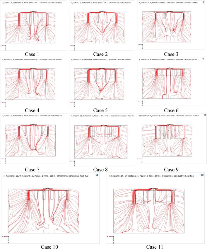
www.nature.com/scientificreports/
the micro-channel. Also, Huang and W ang14 found the optimal fins geometry for the circular micro-channel of
LED lighting heat sinks, numerically. They found that thermal resistance of systems for the optimum design were
decreased by 16.8% and 11.0% than the “initial” and “Type 2” design heat sinks, respectively.
There are also some researchers focused on the novel designs for LED heat sink applications to improve the
thermal managements. Wang et al.15 designed novel tubular oscillating heat pipe with sintered copper particles
for this application and reported that the temperature of LED array was inversely related to the illumination
intensity. Tang et al.16 developed an integrated heat sink with vapor chamber for LED thermal managements and
showed that the high-power LED yields a favorable performance using proposed unit. Kim et al.17 proposed the
using cupper-oxide (CuO) composite coating on aluminum-alloy heat sink to enhance the heat dissipation of
LED module and observed good results due to the improved thermal radiation property. In a different study, Park
et al.18,19 designed a chimney over a circular heat sink in a downlight LED and reported that installing chimney
can increase the cooling efficiency of heat sink up to 20%. Microchannels not only is applicable for LED cool-
ing, but also they are very useful instruments for thermoelectric generators20, natural circulation loops21 and
etc. which different base fluids such as PCM22 and nanofluids23 are widely used to improve their performance.
Nanofluids due to improvements thermal properties have wide applications and motivated researchers to
use them in various aspects. Ben Hamida et al.24 used Ethylene Glycol-Copper Nanofluid under magnetic fields
in an enclosure. Ben Jaballah et al.25 applied the hybrid nanofluid for the performance enhancement of bubble
absorber for cooling applications. Hatami and G anji26, Hatami et al.27 and Tang et al.28 used the nanofluid in
porous media between two coaxial cylinders, wavy microchannel and wavy cavity, respectively. Also, Hatami
et al.29–32 used the optimization techniques such as Response Surface Methodology (RSM) to find the optimize
geometries including nanofluids in heat transfer applications. Massoudi et al.33,34 also investigated the nanofluids
application in free convection under the influence of magnetic field.
Many researchers tried to find the correlations of nanofluids properties in different application. Alsarraf
et al.35 used a multifunctional optimization for the nanofluid properties to cool the electronic heat sink through
the natural convection. Also, Shahsavar et al.36 investigated the variable properties of Fe3O4/CNT/water hybrid
nanofluid on the forced convection of mini-channel heat exchanger and found that the error of computed heat
transfer rate was not exceeded tha 2.91%. Gheynani et al.37 studied the effect of CuO nanoparticles diameter
on heat transfer on non-Newtonian nanofluid in a microtube through the changes in the thermal properties
of nanofluid. Kavusi and T oghraie38 tested the various nanofluids (which have different thermal properties)
on the performance of a heat pipe and reported that nanoparticle concentration had the greatest effect on the
fluid thermal conductivity and thermal resistance. Not only different nanofluids properties were investigated
by researches, but also different applications are considered for them. For instance, Gholami et al.39, Barnoon
et al.40, Toghraie et al.41 and Arasteh et al.42 utilized the nanofluids and investigated their behavior under dif-
ferent conditions for microchannel, cavity with rotating cylinders, L-shaped porous ribs in microchannel and
porous heat sink, respectively.
Based on above discussed literature review, a few studies focused on the nanofluid application for LED cooling
using finned micro-channel. So, to fill this gap of study, it is tried to enhance the cooling efficiency of a LED by
using the Al2O3-water nanofluid and finned arrangements in a microchannel using numerical Galerkin weighted
residual Finite Element Method (GFEM), simultaneously. Also, RSM is used to find the optimized dimensions
for the fin numbers, lengths and thicknesses, numerically.
Problem description
A 3D microchannel filled by Al2O3–water nanofluid is considered as shown in Fig. 1 for LED cooling by fin
arrangements. Microchannel dimensions are: Height = 100 mm; Width = 80 mm and Depth = 50 mm and the
Power of LED = 1, 2 and 3 W as shown in Table 1 in details. The velocity of inlet of nanofluid was considered as
0.001 m/s where the temperature of inlet of nanofluid considered to be 25 °C. The micro-channel is equipped with
fin arrangements for better cooling performance. The main objective of current research is finding the optimum
values for fin numbers, lengths and thicknesses, respectively as shown in Fig. 1 for the micro-channel geometry.
For modeling the problem, a transient flow, incompressible three-dimensional flow from the laws of conserva-
tion of mass, momentum, and energy is considered. The governing equations represent the transient flows are8:
Mass conservation equation:
∂ρ ∂(ρ u) ∂(ρ v) ∂(ρ w)
+ + + =0 (1)
∂t ∂x ∂y ∂z
where ρ refers to the mass density and u, v, and w represent the velocities according to x, y, and z, respectively.
Momentum conservation equation according to x:
∂(ρ u) ∂(ρ u u) ∂(ρ u v) ∂(ρ u w) ∂p ∂ ∂u ∂ ∂u ∂ ∂u
+ + + =− + (η ) + (η ) + (η ) (2)
∂t ∂x ∂y ∂z ∂x ∂x ∂x ∂y ∂y ∂z ∂z
Momentum conservation equation according to y:
∂(ρ v) ∂(ρ u v) ∂(ρ v v) ∂(ρ v w) ∂p ∂ ∂v ∂ ∂v ∂ ∂v
+ + + =− + (η ) + (η ) + (η ) + ρ g (3)
∂t ∂x ∂y ∂z ∂y ∂x ∂x ∂y ∂y ∂z ∂z
Momentum conservation equation according to z:
Scientific Reports | (2021) 11:12610 | https://doi.org/10.1038/s41598-021-91945-2 2
Vol:.(1234567890)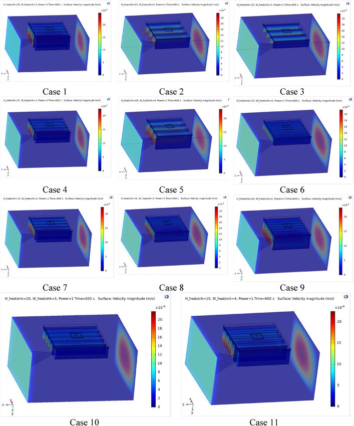
www.nature.com/scientificreports/
Figure 1. (a) Structure of the LED package; (b) Sample Dimensions of heat sink, (c) Geometry of LED cooling
by finned micro-channel filled by nanofluid (COMSOL Multiphysics 5.6, https://www.comsol.com).
Thickness Size Materials
LED-chip 4 µm GaN
Metallization: Bonding Layer 10 µm Au–Si eutectic bonding
1 mm × 1 mm
Die 375 µm Si
Die-attach 50 µm Au-20Sn
127 µm Copper
Substrate 1 cm × 1 cm
381 µm AlN
TIM 50 µm 1 cm × 1 cm Thermal grease
Heat sink – – Al
Table 1. Properties of dimensions and materials of LED package8.
∂(ρ w) ∂(ρ u w) ∂(ρ v w) ∂(ρ w w) ∂p ∂ ∂w ∂ ∂w ∂ ∂w
+ + + =− + (η )+ (η ) + (η ) (4)
∂t ∂x ∂y ∂z ∂z ∂x ∂x ∂y ∂y ∂z ∂z
In above equations, p denotes the pressure, g shows the gravity, and η is related to the dynamic viscosity.
Energy conservation equation:
∂(ρ C T) ∂(ρ u C T) ∂(ρ v C T) ∂(ρ w C T) ∂ ∂T ∂ ∂T ∂ ∂T
+ + + = ( ) + ( ) + ( ) (5)
∂t ∂x ∂y ∂z ∂x ∂x ∂y ∂y ∂z ∂z
where, T and C are the temperature and the specific heat capacity, respectively and λ is the thermal conductivity.
The practical boundary conditions are assumed as follows:
Scientific Reports | (2021) 11:12610 | https://doi.org/10.1038/s41598-021-91945-2 3
Vol.:(0123456789)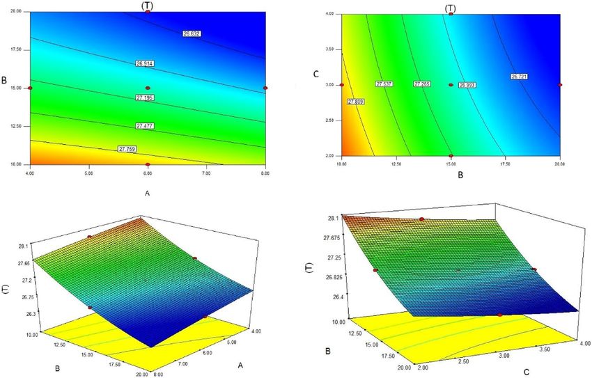
www.nature.com/scientificreports/
• There is a uniform heat flux on top of the die, and other surfaces are adiabatic.
• The microchannel inlet boundary condition is considered to be the uniform temperature of T
in with a uniform
velocity of Uin.
• At microchannel outlet, Pressure outlet boundary condition with zero gradients is assumed.
• No slip condition is imposed on the surface of microchannel walls.
• All the microchannel outer walls are insulated.
In this study, the thermal conductivity of the materials used in the LED package as well as the water properties
are considered dependent on t emperature8. For water temperature-dependent properties:
(A) Dynamic viscosity:
273.15 K < T < 473.15 K:
η = 1.3799566804 − 0.021224019151∗T + 1.3604562827∗10−4 ∗T2 − 4.6454090319∗10−7 ∗T3
(6)
+ 8.9042735735∗10−10∗ T4 − 9.0790692686∗10−13 ∗T5 + 3.8457331488∗10−16 ∗T6
473.15 < T < 553.15 K:
η = 0.00401235783 − 2.10746715 ∗ 10−5 ∗ T + 3.85772275 ∗ 10−8 ∗ T2 − 2.39730284 ∗ 10−11 ∗ T3 (7)
T in K and dynamic viscosity in Pa.s
(B) Thermal capacity:
273.15 < T < 553.15 K
C = 12010.1471−80.4072879∗T +0.30866854∗T2 −5.38186884∗10−4 ∗T3 +3.62536437∗10−7 ∗T4 (8)
T in K and Thermal Capacity in J/(kg*K).
(C) Mass density
273.15 < T < 293.15 K.
ρ = 0.000063092789034∗T3 −0.060367639882855∗T2 +18.9229382407066∗T −950.704055329848 (9)
293.15 < T < 373.15 K.
ρ = 0.000010335053319∗T3 −0.013395065634452∗T2 +4.969288832655160∗T+432.257114008512 (10)
T in K and mass density in kg/m3.
(D) Thermal conductivity
273.15 < T < 1000 K
= −0.869083936 + 0.00894880345∗T − 1.58366345∗10−5 ∗T2 + 7.97543259∗10−9 ∗T3 (11)
T in K and Thermal conductivity in W/(m*K). For the nanofluid properties, following equations are a pplied35:
ρnf = (1 − φ)ρbf + ϕρp (12)
(1 − ϕ) ρCp bf + ϕ(ρCp )p
Cpnf = (13)
ρnf
knf
= 0.991 + 0.276Tϕ + 77.6ϕ 2 + 3641.231Tϕ 2 +
kbf
(14)
0.00217
− 6.01 × 10⁻⁶ T 2 − 3647.099Tϕ sin (ϕ)
sin (T − ϕ)
µnf = µstatic + µBrownian (15)
µf 4
µf kb T
(16)
µnf = + 5 × 10 βϕρf Cp f f (T, ϕ)
(1 − ϕ)2.5 kf Pr ρp ds
where
T
f (T, ϕ) = 2.8217 × 10⁻² ϕ + 3.917 × 10⁻³ + −3.0669 × 10⁻² ϕ − 3.91123 × 10⁻³ (17)
T0
Scientific Reports | (2021) 11:12610 | https://doi.org/10.1038/s41598-021-91945-2 4
Vol:.(1234567890)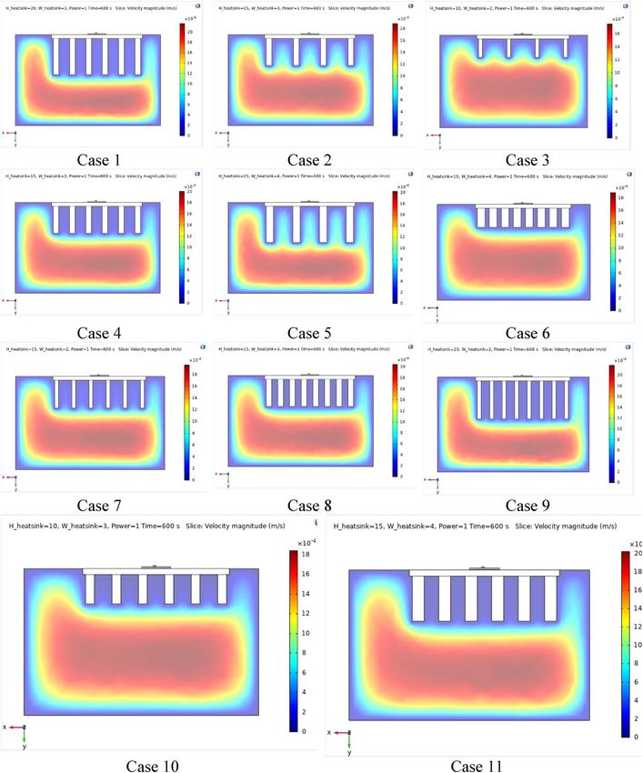
www.nature.com/scientificreports/
Junction Temperature (°C) (max. Temperature of Heat sink (°C) (min.
Predefined mesh size Mesh elements temperature) temperature)
Extremely coarse 3641 60.165 52.416
Extra coarse 6019 60.231 52.623
Coarser 10,766 60.254 52.794
Coarse 17,989 60.273 52.931
Normal 26,436 60.289 53.087
Fine 45,255 60.370 53.222
Finer 136,857 60.968 53.568
Table 2. Mesh independency of the micro-channel.
Parameter Description Level 1 Level 2 Level 3
A Fin number 4 6 8
B Fin Length 10 15 20
C Fin thickness 2 3 4
Table 3. Geometry parameters of fins arrangement for microchanel and defined levels.
β = 8.4407(100ϕ)−1.07304 (18)
Methodology of solution
In this study, COMSOL-Multiphysics commercial Galerkin finite element method (GFEM) software is applied
for the modeling of problem. GFEM is a numerical method to discretize and solve the coupled partial differen-
tial equations governed on any physical phenomenon. GFEM by COMSOL is not only accurate and adaptable,
but also it is simple in modeling the complicated physics as well as the time-dependent simulation of physical
problems in environment, chemical, energy, electrical, heat transfer and other multi-physic problems. Actually,
GFEM with COMSOL can help the user to solve the problems with multi-physics such as electrical–mechanical
systems easily, while the solution of these problems by other commercial software (such as FVM based ANSYS-
FULENT) or by hand is not p ossible8. During the modeling process, user must define the boundary conditions
after the geometry modeling to show the conditions which must be responded during the solution. Boundary
conditions can be defined as the distributed forces, point forces, positional constraints and thermal effects such
as temperature changes or applied heat energy. Additionally, the GFEM user can certainly spot any vulnerability
in design with the complete visualizations GFEM produces and then use the novel data to have a new d esign8.
Central Composite Design or CCD is a technique of Design of Experiment (DoE) to achieve the suitable
points of each independent variable based on their possible values (level). CCD contains an imbedded factorial
or fractional factorial design with center points which is improved by a “star points” group and let’s estimate of
curvature. After introducing the minimum number of cases with CCD, RSM must be applied to find the optimum
values for the fin numbers, lengths and thicknesses. Actually, RSM find a first or second-order polynomial relation
between the response (here temperature) and independent variables (fin numbers, lengths and thicknesses). This
polynomial equation consider the interaction between the and surface curvatures and fitted in the shape o f31,32
n
n
n
n
Aii xi2 +
y = A0 + Ai xi + Aij xi xj
i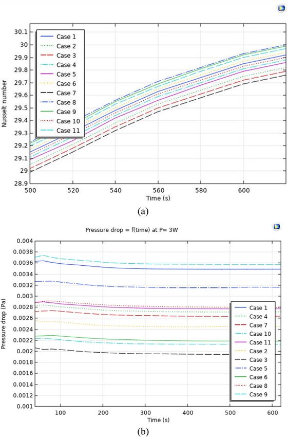
www.nature.com/scientificreports/
Level of parameters
Case number Parameter, A Parameter, B Parameter, C
1 6 20 3
2 4 15 3
3 4 10 2
4 6 15 3
5 4 20 4
6 8 10 4
7 6 15 2
8 8 15 3
9 8 20 2
10 6 10 3
11 6 15 4
Table 4. CCD proposed cases for finned geometry with Power of LED = 1, 2 and 3 W Microchannel
dimensions: Height = 100 mm; Width = 80 mm and Depth = 50 mm.
Figure 2. Mesh generated in the domain and LED finned section (COMSOL Multiphysics 5.6, https://www.
comsol.com).
where n indicates the number of responses. If each of responses or factors drops outside their desirability range,
the overall function will be zero. More details about this optimization method can be found i n31,32.
Results and discussions
As described in above sections, it is tried to obtain an optimized geometry for the microchannel filled by nano-
fluid for LED cooling. Dimensions of LED package as well as the materials are presented in Table 1. Based on
previous study in8, the best materials for LED-chip is GaN, Die from Si, Die-attach is made by Au-20Sn, substrate
is copper and heat sink material is considered to be Al. LED has 1, 2 and 3 W power and the microchannel
dimensions was Height = 100 mm; Width = 80 mm and Depth = 50 mm. In order to find a suitable mesh grid,
numerous mesh numbers (from extremely coarse to finer mesh) were used for this 3D model as demonstrated in
Table 2. These values confirm that fine mesh is a suitable grid type for this study due to its accuracy and accept-
able time of calculations. Then, CCD is applied to have the proposed geometries for the considered parameters
as shown in Table 3. Fin number, fin diameter and fin thicknesses are three main parameters under the study
which their levels were presented in Table 3. CCD proposed 11 cases as the minimum required cases which are
shown in Table 4 by details.
To validate our generated 3D model with the previous model of Ha and Graham7, the temperature distribu-
tion of the LED package is simulated with the equivalent settings modeled by Ha and Graham7 as presented
in Fig. 1 and generated mesh is depicted in Fig. 2. Figure 3 shows the 3D model simulated by Ha and G raham7
using the commercial ANSYS-FLUENT software where Power of LED lamp was 1 W, heat transfer coefficient
Scientific Reports | (2021) 11:12610 | https://doi.org/10.1038/s41598-021-91945-2 6
Vol:.(1234567890)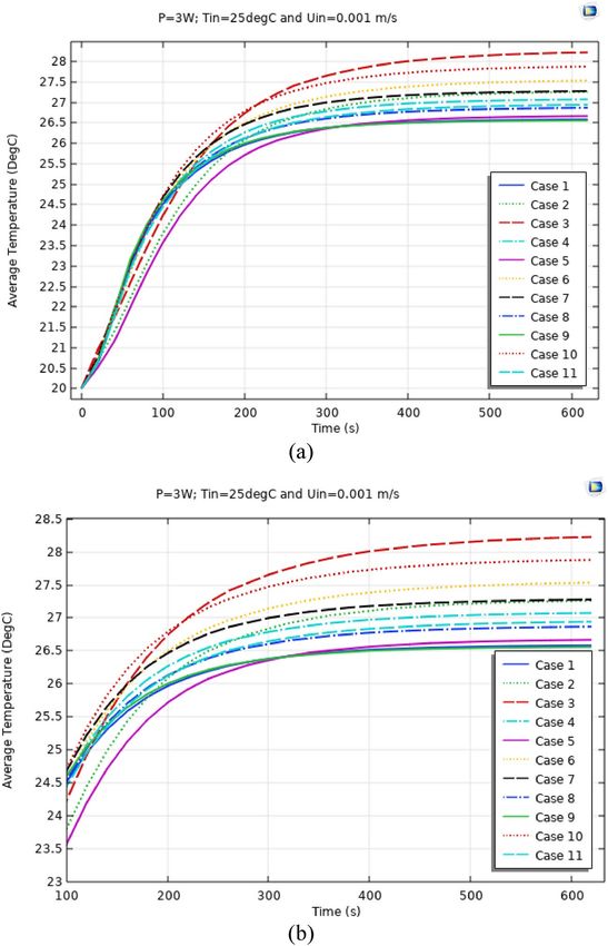
www.nature.com/scientificreports/
Figure 3. Temperature distribution of the LED package: (a): Our 3D code (b): Ha and Graham code7 (c),
Comparison of vertical temperature profile along the center line (z axis)8 (COMSOL Multiphysics 5.6, https://
www.comsol.com).
was 10 W/m2/K and the temperature of ambient was 25 °C. From the Fig. 3a,b it can be observed that current
code which also was used in8 has similar results with7 where the minimum and maximum temperatures for both
methods are about 53.22 °C and 60.37 °C, respectively. Actually a minor temperature difference between these
two models is existed which does not exceed than 0.001%. Also, the vertical temperature profile along the LED
package centerline is plotted in Fig. 3c, which a good agreement between current 3D COMSOL-Multiphysics
model and 3D ANSYS-FLUENT model of Ha and G raham7 was observed.
Figures 4, 5 and 6 show the temperatures, velocities and streamlines of nanofluid in both LED and micro-
channel domains and the results of junction temperature for three LED powers (1, 2 and 3 W) of all 11 designed
cases are shown in Table 5 at final time, t = 620 s. It is obvious that when the number of fins increased the cool-
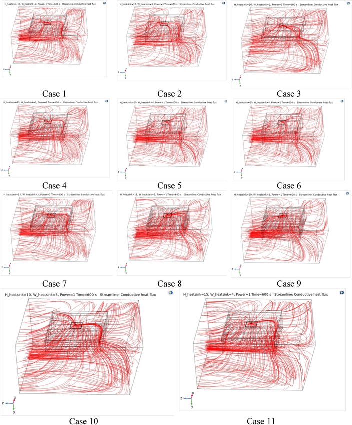
ing process is better occurred and maximum temperature on the LED is decreased. Figures 7 and 8 shows the
2D contours of velocity and streamlines of 11 cases, respectively. It can be observed that cases 6, 8 and 9 due to
greater fin numbers (8 fins) has more compact microchannel and the velocity between the fins is greater. But
for the cases 2, 3, 5 and 10 nanofluids slowly flow between the fins due to more free spaces. So, this parameter
has an important role in heat transfer due to effect on both heat transfer surface and changing the flows regime.
Also, the cases which have lengthy fins (Cases 1, 5 and 9) have smaller region of maximum velocity in micro-
channel (red area) due to making obstacles against the flow. Because these three parameters has influence on
each other, a parametric study is required to find the most important parameter among them. Figure 9 shows
the average temperatures during the time for P = 3 W. Cases 3, 10 and 6 have maximum temperatures (worst
cooling performance) and cases 9, 1 and 5 have the minimum temperatures or best cooling performances. From
Table 4, it can be seen that Cases 3, 10 and 6 are in lowest level of fin length, while cases 9, 1 and 5 are in upper
level of fins length. Figures 10 and 11 also present the temperatures during the time when LED power is 2 W
and 1 W, respectively. These figures confirm the same results of cooling the LED by finned microchannel. Also, it
can be found that number of fins is another important parameter while the fins thickness is not very significant
Scientific Reports | (2021) 11:12610 | https://doi.org/10.1038/s41598-021-91945-2 7
Vol.:(0123456789)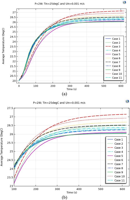
www.nature.com/scientificreports/
Figure 4. Temperature contours for the finned micro-channel of different geometries (11 Cases) (COMSOL
Multiphysics 5.6, https://www.comsol.com).
Scientific Reports | (2021) 11:12610 | https://doi.org/10.1038/s41598-021-91945-2 8
Vol:.(1234567890)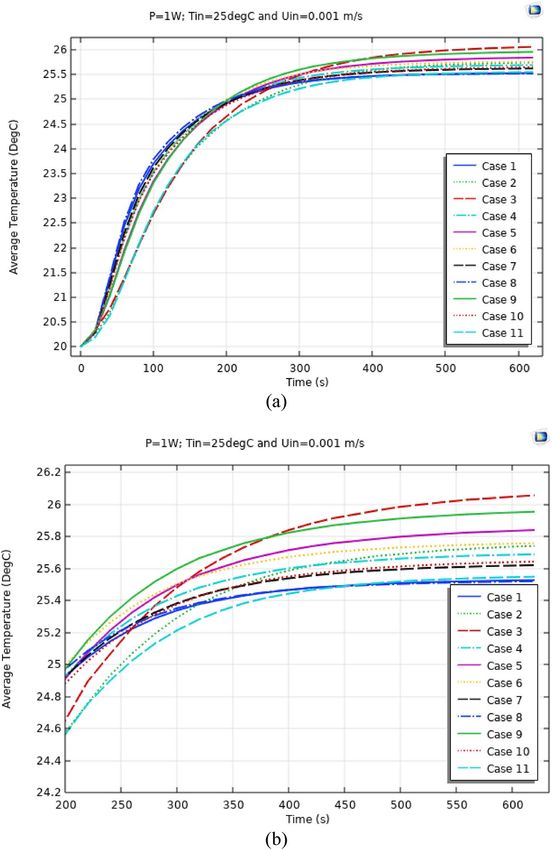
www.nature.com/scientificreports/
Figure 5. Velocity contours for the finned micro-channel of different geometries (11 Cases) (COMSOL
Multiphysics 5.6, https://www.comsol.com).
Scientific Reports | (2021) 11:12610 | https://doi.org/10.1038/s41598-021-91945-2 9
Vol.:(0123456789)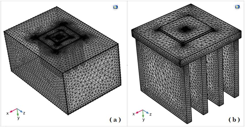
www.nature.com/scientificreports/
Figure 6. Streamline contours for the finned micro-channel of different geometries (11 Cases) (COMSOL
Multiphysics 5.6, https://www.comsol.com).
Scientific Reports | (2021) 11:12610 | https://doi.org/10.1038/s41598-021-91945-2 10
Vol:.(1234567890)www.nature.com/scientificreports/
Case P=1 W P=2 W P=3 W
1 25.52701 26.05767 26.58474
2 25.74088 26.50567 27.26295
3 26.05708 27.14766 28.22671
4 25.68918 26.38428 27.07537
5 25.83996 26.11025 26.66800
6 25.75795 26.69111 27.53490
7 25.62041 26.52071 27.27858
8 25.51977 26.24666 26.86830
9 25.95494 26.04184 26.56050
10 25.64296 26.92147 27.88059
11 25.54928 26.29494 26.94251
Table 5. Results of final temperature (t = 620 s) for designed geometries.
compared to two other parameters due to its small effect of the cooling performance resulted from small effect
on both surface and flow regime. From this figures, it can be concluded that by different designs of fins arrange-
ments, it is possible to increase the nanofluid temperature up to 6.5% which enhanced the LED cooling process.
Figure 12 shows these descriptions in 2D and 3D contours to find the effect of each parameter on the results. As
seen, slope of curves and surfaces for the parameter B is greater than parameter A and greater than parameter
C. Also the minimum temperatures (best cooling) is occurred when all the parameters are in upper levels, so
desirability function of optimized case in Fig. 13 is depicted which illustrate that better case (desirability = 1)
occurs when B = 20 and A = 8. Based on these results, RSM proposed the best cases which is presented in Table 6
as optimized geometries. Figure 14 compares the Nusselt number and pressure drops of all cases. Since the pres-
sure drops are very small, so it can be negligible in optimization and single objective is performed for this case
of study. The results of optimized case is depicted in Fig. 15, while the effect of different nanoparticles volume
fraction is presented in Fig. 16 which says that larger nanoparticles volume fraction has greater Nusselt number
due to temperature dependent properties of base water and greater thermal conductivity of nanofluid as well as
the lower pressure drop for smaller nanoparticles concentrations.
Conclusion
In this study, the geometry of a finned microchannel is optimized for application in LED cooling by nanofluids,
numerically. COMSOL-Multiphysics commercial code was used and Al2O3-water as the cooling nanofluid flow
was selected as the working fluid. Three powers (1, 2 and 3 W) are used for the LED power output and to find
the optimized arrangement of fins for reaching the minimum temperature (as cooling efficiency), Central com-
posite design (CCD) was applied to propose minimum possible geometries (11 Cases). Finally, GFEM results
of modeling were optimized by the Response Surface Method (RSM) which confirmed that the optimized case
Scientific Reports | (2021) 11:12610 | https://doi.org/10.1038/s41598-021-91945-2 11
Vol.:(0123456789)www.nature.com/scientificreports/
Figure 7. 2D Velocity contours for the finned micro-channel of different geometries (11 Cases) (COMSOL
Multiphysics 5.6, https://www.comsol.com).
Scientific Reports | (2021) 11:12610 | https://doi.org/10.1038/s41598-021-91945-2 12
Vol:.(1234567890)www.nature.com/scientificreports/
Figure 8. 2D Streamline contours for the finned micro-channel of different geometries (11 Cases) (COMSOL
Multiphysics 5.6, https://www.comsol.com).
Scientific Reports | (2021) 11:12610 | https://doi.org/10.1038/s41598-021-91945-2 13
Vol.:(0123456789)www.nature.com/scientificreports/
Figure 9. Average Temp. when P = 3 W for different 11 cases (a) complete view, (b) zoomed view.
Scientific Reports | (2021) 11:12610 | https://doi.org/10.1038/s41598-021-91945-2 14
Vol:.(1234567890)www.nature.com/scientificreports/
Figure 10. Average Temp. when P = 2 W for different 11 cases (a) complete view, (b) zoomed view.
Scientific Reports | (2021) 11:12610 | https://doi.org/10.1038/s41598-021-91945-2 15
Vol.:(0123456789)www.nature.com/scientificreports/
Figure 11. Average Temp. when P = 1 W for different 11 cases (a) complete view, (b) zoomed view.
Scientific Reports | (2021) 11:12610 | https://doi.org/10.1038/s41598-021-91945-2 16
Vol:.(1234567890)www.nature.com/scientificreports/
Figure 12. 2D and 3D contour of geometry parameters on temperature.
Figure 13. Desirability function of optimized geometry.
Scientific Reports | (2021) 11:12610 | https://doi.org/10.1038/s41598-021-91945-2 17
Vol.:(0123456789)www.nature.com/scientificreports/
Number A B C
1 8 20 4 Selected
2 8 19.64 3.89
3 6 19.83 3.17
4 8 18.84 2.63
5 8 19.06 2.51
Table 6. Optimized geometry proposed by RSM.
Figure 14. (a) Nusselt number (b) Pressure drops graphs for P = 3 W for all designed cases.
Scientific Reports | (2021) 11:12610 | https://doi.org/10.1038/s41598-021-91945-2 18
Vol:.(1234567890)www.nature.com/scientificreports/
Figure 15. Velocity, temperature and streamline for optimized case (COMSOL Multiphysics 5.6, https://www.
comsol.com).
Scientific Reports | (2021) 11:12610 | https://doi.org/10.1038/s41598-021-91945-2 19
Vol.:(0123456789)www.nature.com/scientificreports/
Figure 16. Effect of different nanoparticles concentration on Nusselt number of the optimized case.
include parameters as Fin numbers = 8, Fin length = 20 and Fin thickness = 4 where nanoparticles with φ = 0.05
caused maximum cooling efficiency for this case by greater Nusselt number and lower pressure drop.
Received: 11 April 2021; Accepted: 3 June 2021
References
1. Ben Hamida, M. B. & Charrada, K. Application of a three-dimensional model for a study of the energy transfer of a high-pressure
mercury horizontal lamp. Phys. Plasmas. 19(6), 063504 (2012).
2. Ben Hamida, M. B., Helali, H., Araoud, Z. & Charrada, K. Contrast between The vertical and horizontal mercury discharge lamps.
Phys. Plasmas. 18(6), 063506 (2011).
3. Ben Hamida, M. B. & Charrada, K. A three-dimensional thermal study of a mercury discharge lamp with double envelope for
different orientations. J. Phys. Plasmas. 81(2), 905810202 (2014).
4. Ferjani, B. & Ben Hamida, M. B. Thermal study of the atomic ratio effect on a cylindrical and an ellipsoidal shaped HgTlI discharge
lamps. Eur. Phys. J. D. 73(9), 208 (2019).
5. Bensalah, S. & Ben Hamida, M. B. Heat transfer enhancement of circular and square LED geometry. Int. J. Numer. Methods Heat
Fluid Flow 29(5), 1877–1898 (2019).
6. Ben Salah, S. & Ben Hamida, M. B. Alternate PCM with air cavities in LED heat sink for transient thermal management. Int. J.
Numer. Methods Heat Fluid Flow https://doi.org/10.1108/HFF-02-2019-0099 (2019).
Scientific Reports | (2021) 11:12610 | https://doi.org/10.1038/s41598-021-91945-2 20
Vol:.(1234567890)www.nature.com/scientificreports/
7. Ha, M. & Graham, S. Development of a thermal resistance model for chip-on-board packaging of high power LED arrays. Micro-
electron. Reliab. 52(5), 836–844 (2012).
8. Ben Hamida, M. B., Charrada, K., Almeshaal, M. A. & Chamkha, A. A three-dimensional thermal analysis and optimization of
square light edding diode subcomponents. Int. Commun. Heat Mass Transfer 120, 105016 (2021).
9. Jia, Y.-L. et al. Large current efficiency enhancement in the CsPbBr 3 perovskite light-emitting diodes assisted by an ultrathin
buffer layer. J. Lumin. 209, 251–257 (2019).
10. Fu-Xing, Y. et al. Full coverage all-inorganic cesium lead halide perovskite film for high-efficiency light-emitting diodes assisted
by 1,3,5-tri(m-pyrid-3-yl-phenyl)benzene. Organ. Electron. 50, 480–484 (2017).
11. Minqiang, P., Haozhong, H. & Guanping, D. Experimental study of the performance of cutting copper fiber oriented sintered heat
sinks for the water cooling of LEDs. Appl. Therm. Eng. 179, 115738 (2020).
12. Xiaohui, L. et al. Thermal management of high-power LED based on thermoelectric cooler and nanofluid-cooled microchannel
heat sink. Appl. Therm. Eng. 172, 115165 (2020).
13. Lin, X. et al. Experimental study and Taguchi analysis on LED cooling by thermoelectric cooler integrated with microchannel heat
sink. Appl. Energy 242, 232–238 (2019).
14. Huang, C.-H. & Wang, G.-J. A design problem to estimate the optimal fin shape of LED lighting heat sinks. Int. J. Heat Mass Transf.
106, 1205–1217 (2017).
15. Wang, H., Jian, Qu., Peng, Y. & Sun, Q. Heat transfer performance of a novel tubular oscillating heat pipe with sintered copper
particles inside flat-plate evaporator and high-power LED heat sink application. Energy Convers. Manag. 189, 215–222 (2019).
16. Tang, Y. et al. Thermal management of high-power LEDs based on integrated heat sink with vapor chamber. Energy Convers.
Manag. 151, 1–10 (2017).
17. Kim, D., Lee, J., Kim, J., Choi, C.-H. & Chung, W. Enhancement of heat dissipation of LED module with cupric-oxide composite
coating on aluminum-alloy heat sink. Energy Convers. Manag. 106, 958–963 (2015).
18. Park, S.-J., Jang, D., Yook, S.-J. & Lee, K.-S. Optimization of a chimney design for cooling efficiency of a radial heat sink in a LED
downlight. Energy Convers. Manag. 114, 180–187 (2016).
19. Park, S.-J., Jang, D. & Lee, K.-S. Thermal performance improvement of a radial heat sink with a hollow cylinder for LED downlight
applications. Int. J. Heat Mass Transf. 89, 1184–1189 (2015).
20. Junwei, L. et al. Model development and performance evaluation of thermoelectric generator with radiative cooling heat sink.
Energy Convers. Manag. 216, 112923 (2020).
21. Ho, C. J. & Chung, Y. N. Chi-Ming Lai, Thermal performance of Al2O3/water nanofluid in a natural circulation loop with a mini-
channel heat sink and heat source. Energy Convers. Manag. 87, 848–858 (2014).
22. Cyril Reuben, R. et al. Thermal performance of nano-enriched form-stable PCM implanted in a pin finned wall-less heat sink for
thermal management application. Energy Convers. Manag. 226, 113466 (2020).
23. Hatami, M. & Ganji, D. D. Thermal and flow analysis of microchannel heat sink (MCHS) cooled by Cu–water nanofluid using
porous media approach and least square method. Energy Convers. Manag. 78, 347–358 (2014).
24. Ben Hamida, M. B. & Charrada, K. Natural convection heat transfer in an enclosure filled with an ethylene glycol-copper nanofluid
under magnetic fields. Numer. Heat Transf. Part A Appl. 67(8), 902–992 (2015).
25. Ben Jaballah, R., Ben Hamida, M. B., Saleh, J. & Almeshaal, M. A. Enhancement of the performance of bubble absorber using
hybrid nanofluid as a cooled absorption system. Int. J. Numer. Meth. Heat Fluid Flow 29(10), 3857–38719 (2019).
26. Hatami, M. & Ganji, D. D. Heat transfer and flow analysis for SA-TiO2 non-Newtonian nanofluid passing through the porous
media between two coaxial cylinders. J. Mol. Liq. 188, 155–161. https://doi.org/10.1016/j.molliq.2013.10.009 (2013).
27. Zhou, J., Hatami, M., Song, D. & Jing, D. Design of microchannel heat sink with wavy channel and its time-efficient optimization
with combined RSM and FVM methods. Int. J. Heat Mass Transfer 103, 715–724 (2016).
28. Tang, W., Hatami, M., Zhou, J. & Jing, D. Natural convection heat transfer in a nanofluid-filled cavity with double sinusoidal wavy
walls of various phase deviations. Int. J. Heat Mass Transfer 115, 430–440 (2017).
29. Hatami, M., Song, D. & Jing, D. Optimization of a circular-wavy cavity filled by nanofluid under the natural convection heat transfer
condition. Int. J. Heat Mass Transf. 98, 758–767 (2016).
30. Hatami, M. Nanoparticles migration around the heated cylinder during the RSM optimization of a wavy-wall enclosure. Adv.
Powder Technol. 28(3), 890–899 (2017).
31. Hatami, M. & Jing, D. Optimization of wavy direct absorber solar collector (WDASC) using Al 2 O 3-water nanofluid and RSM
analysis. Appl. Therm. Eng. 121, 1040–1050 (2017).
32. Hatami, M., Zhou, J., Geng, J., Song, D. & Jing, D. Optimization of a lid-driven T-shaped porous cavity to improve the nanofluids
mixed convection heat transfer. J. Mol. Liq. 231, 620–631 (2017).
33. Massoudi, M. D., Ben Hamida, M. B. & Almeshaal, M. A. Free convection and thermal radiation of nanofluid inside nonagon
inclined cavity containing a porous medium influenced by magnetic field with variable direction in the presence of uniform heat
generation/absorption. Int. J. Numer. Meth. Heat Fluid Flow https://doi.org/10.1108/HFF-04-2020-0223 (2020).
34. Massoudi, M. D. & Ben Hamida, M. B. MHD natural convection and thermal radiation of diamond–water nanofluid around
rotating elliptical baffle inside inclined trapezoidal cavity. Eur. Phys. J. Plus 135, 1–24 (2020).
35. Alsarraf, J. et al. Numerical investigation on the effect of four constant temperature pipes on natural cooling of electronic heat sink
by nanofluids: A multifunctional optimization. Adv. Powder Technol. 31(1), 416–432 (2020).
36. Shahsavar, A., Ali, G., Pouyan, T. S., Davood, T. & Hamzeh, S. Impact of variable fluid properties on forced convection of Fe3O4/
CNT/water hybrid nanofluid in a double-pipe mini-channel heat exchanger. J. Therm. Anal. Calorim. 137(3), 1031–1043 (2019).
37. Gheynani, A. R. et al. Investigating the effect of nanoparticles diameter on turbulent flow and heat transfer properties of non-
Newtonian carboxymethyl cellulose/CuO fluid in a microtube. Int. J. Numer. Methods Heat Fluid Flow 2, 2 (2019).
38. Kavusi, H. & Toghraie, D. A comprehensive study of the performance of a heat pipe by using of various nanofluids. Adv. Powder
Technol. 28(11), 3074–3084 (2017).
39. Gholami, M. R. et al. The effect of rib shape on the behavior of laminar flow of oil/MWCNT nanofluid in a rectangular microchan-
nel. J. Therm. Anal. Calorim. 134(3), 1611–1628 (2018).
40. Barnoon, P., Davood, T., Reza Balali, D. & Hossein, A. MHD mixed convection and entropy generation in a lid-driven cavity with
rotating cylinders filled by a nanofluid using two phase mixture model. J. Magn. Magn. Mater. 483, 224–248 (2019).
41. Toghraie, D., Mahmoudi, M., Akbari, O. A., Pourfattah, F. & Heydari, M. The effect of using water/CuO nanofluid and L-shaped
porous ribs on the performance evaluation criterion of microchannels. J. Therm. Anal. Calorim. 135(1), 145–159 (2019).
42. Arasteh, H. et al. Optimal arrangements of a heat sink partially filled with multilayered porous media employing hybrid nanofluid.
J. Therm. Anal. Calorim. 137(3), 1045–1058 (2019).
Author contributions
Both authors contributed in all sections of modeling and discussion sections.
Competing interests
The authors declare no competing interests.
Scientific Reports | (2021) 11:12610 | https://doi.org/10.1038/s41598-021-91945-2 21
Vol.:(0123456789)www.nature.com/scientificreports/
Additional information
Correspondence and requests for materials should be addressed to M.H.
Reprints and permissions information is available at www.nature.com/reprints.
Publisher’s note Springer Nature remains neutral with regard to jurisdictional claims in published maps and
institutional affiliations.
Open Access This article is licensed under a Creative Commons Attribution 4.0 International
License, which permits use, sharing, adaptation, distribution and reproduction in any medium or
format, as long as you give appropriate credit to the original author(s) and the source, provide a link to the
Creative Commons licence, and indicate if changes were made. The images or other third party material in this
article are included in the article’s Creative Commons licence, unless indicated otherwise in a credit line to the
material. If material is not included in the article’s Creative Commons licence and your intended use is not
permitted by statutory regulation or exceeds the permitted use, you will need to obtain permission directly from
the copyright holder. To view a copy of this licence, visit http://creativecommons.org/licenses/by/4.0/.
© The Author(s) 2021
Scientific Reports | (2021) 11:12610 | https://doi.org/10.1038/s41598-021-91945-2 22
Vol:.(1234567890)You can also read