On-Demand Infrastructure with Secure Networks
←
→
Page content transcription
If your browser does not render page correctly, please read the page content below
On-Demand Infrastructure
with Secure Networks
REFERENCE ARCHITECTURE

On-Demand Infrastructure
                                                                                                                                                  with Secure Networks

Table of Contents

Executive Summary .  .  .  .  .  .  .  .  .  .  .  .  .  .  .  .  .  .  .  .  .  .  .  .  .  .  .  .  .  .  .  .  .  .  .  .  .  .  .  .  .  .  .  .  .  .  .  .  .  .  .  .  .  .  .  .  .  .  .  . 3
Audience.  .  .  .  .  .  .  .  .  .  .  .  .  .  .  .  .  .  .  .  .  .  .  .  .  .  .  .  .  .  .  .  .  .  .  .  .  .  .  .  .  .  .  .  .  .  .  .  .  .  .  .  .  .  .  .  .  .  .  .  .  .  .  .  .  .  .  .  .  . 3
Overview.  .  .  .  .  .  .  .  .  .  .  .  .  .  .  .  .  .  .  .  .  .  .  .  .  .  .  .  .  .  .  .  .  .  .  .  .  .  .  .  .  .  .  .  .  .  .  .  .  .  .  .  .  .  .  .  .  .  .  .  .  .  .  .  .  .  .  .  .  . 3
What Is an On-Demand Infrastructure with Secure Networks? .  .  .  .  .  .  .  .  .  .  .  .  .  .  .  .  .  .  .  .  .  . 4
Architecture Overview.  .  .  .  .  .  .  .  .  .  .  .  .  .  .  .  .  .  .  .  .  .  .  .  .  .  .  .  .  .  .  .  .  .  .  .  .  .  .  .  .  .  .  .  .  .  .  .  .  .  .  .  .  .  .  .  .  . 5
Cluster Overview.  .  .  .  .  .  .  .  .  .  .  .  .  .  .  .  .  .  .  .  .  .  .  .  .  .  .  .  .  .  .  .  .  .  .  .  .  .  .  .  .  .  .  .  .  .  .  .  .  .  .  .  .  .  .  .  .  .  .  .  .  .  . 8
Management Cluster .  .  .  .  .  .  .  .  .  .  .  .  .  .  .  .  .  .  .  .  .  .  .  .  .  .  .  .  .  .  .  .  .  .  .  .  .  .  .  .  .  .  .  .  .  .  .  .  .  .  .  .  .  .  .  .  .  .  . 8
Edge Cluster. .  .  .  .  .  .  .  .  .  .  .  .  .  .  .  .  .  .  .  .  .  .  .  .  .  .  .  .  .  .  .  .  .  .  .  .  .  .  .  .  .  .  .  .  .  .  .  .  .  .  .  .  .  .  .  .  .  .  .  .  .  .  .  .  .  . 9
Payload Clusters .  .  .  .  .  .  .  .  .  .  .  .  .  .  .  .  .  .  .  .  .  .  .  .  .  .  .  .  .  .  .  .  .  .  .  .  .  .  .  .  .  .  .  .  .  .  .  .  .  .  .  .  .  .  .  .  .  .  .  .  .  .  . 9
Physical Component Details.  .  .  .  .  .  .  .  .  .  .  .  .  .  .  .  .  .  .  .  .  .  .  .  .  .  .  .  .  .  .  .  .  .  .  .  .  .  .  .  .  .  .  .  .  .  .  .  .  .  .  .  . 9
       Compute .  .  .  .  .  .  .  .  .  .  .  .  .  .  .  .  .  .  .  .  .  .  .  .  .  .  .  .  .  .  .  .  .  .  .  .  .  .  .  .  .  .  .  .  .  .  .  .  .  .  .  .  .  .  .  .  .  .  .  .  .  .  .  .  .  .  .  .  . 9
       Storage. .  .  .  .  .  .  .  .  .  .  .  .  .  .  .  .  .  .  .  .  .  .  .  .  .  .  .  .  .  .  .  .  .  .  .  .  .  .  .  .  .  .  .  .  .  .  .  .  .  .  .  .  .  .  .  .  .  .  .  .  .  .  .  .  .  .  .  .  . 10
       Network.  .  .  .  .  .  .  .  .  .  .  .  .  .  .  .  .  .  .  .  .  .  .  .  .  .  .  .  .  .  .  .  .  .  .  .  .  .  .  .  .  .  .  .  .  .  .  .  .  .  .  .  .  .  .  .  .  .  .  .  .  .  .  .  .  .  .  .  . 10
Software-Defined Data Center Component Details .  .  .  .  .  .  .  .  .  .  .  .  .  .  .  .  .  .  .  .  .  .  .  .  .  .  .  .  .  .  . 11
       vSphere Data Center Logical Design.  .  .  .  .  .  .  .  .  .  .  .  .  .  .  .  .  .  .  .  .  .  .  .  .  .  .  .  .  .  .  .  .  .  .  .  .  .  .  .  .  .  . 11
              vCenter Orchestrator .  .  .  .  .  .  .  .  .  .  .  .  .  .  .  .  .  .  .  .  .  .  .  .  .  .  .  .  .  .  .  .  .  .  .  .  .  .  .  .  .  .  .  .  .  .  .  .  .  .  .  .  .  . 15
vCloud Automation Center.  .  .  .  .  .  .  .  .  .  .  .  .  .  .  .  .  .  .  .  .  .  .  .  .  .  .  .  .  .  .  .  .  .  .  .  .  .  .  .  .  .  .  .  .  .  .  .  .  .  .  .  . 19
       vCloud Automation Center Appliances.  .  .  .  .  .  .  .  .  .  .  .  .  .  .  .  .  .  .  .  .  .  .  .  .  .  .  .  .  .  .  .  .  .  .  .  .  .  .  .  . 19
       vCloud Automation Center IaaS Web Servers.  .  .  .  .  .  .  .  .  .  .  .  .  .  .  .  .  .  .  .  .  .  .  .  .  .  .  .  .  .  .  .  .  .  . 19
       vCloud Automation Center IaaS Managers. .  .  .  .  .  .  .  .  .  .  .  .  .  .  .  .  .  .  .  .  .  .  .  .  .  .  .  .  .  .  .  .  .  .  .  .  . 20
       Distributed Execution Managers and the vSphere Agent. .  .  .  .  .  .  .  .  .  .  .  .  .  .  .  .  .  .  .  .  .  .  .  . 20
       Monitoring.  .  .  .  .  .  .  .  .  .  .  .  .  .  .  .  .  .  .  .  .  .  .  .  .  .  .  .  .  .  .  .  .  .  .  .  .  .  .  .  .  .  .  .  .  .  .  .  .  .  .  .  .  .  .  .  .  .  .  .  .  .  .  .  .  .  . 20
       vCenter Operations Manager.  .  .  .  .  .  .  .  .  .  .  .  .  .  .  .  .  .  .  .  .  .  .  .  .  .  .  .  .  .  .  .  .  .  .  .  .  .  .  .  .  .  .  .  .  .  .  .  .  . 20
       vCenter Log Insight. .  .  .  .  .  .  .  .  .  .  .  .  .  .  .  .  .  .  .  .  .  .  .  .  .  .  .  .  .  .  .  .  .  .  .  .  .  .  .  .  .  .  .  .  .  .  .  .  .  .  .  .  .  .  .  .  .  . 20
vCloud Automation Center Operational Configuration .  .  .  .  .  .  .  .  .  .  .  .  .  .  .  .  .  .  .  .  .  .  .  .  .  .  .  . 21
       NSX for vSphere Configuration.  .  .  .  .  .  .  .  .  .  .  .  .  .  .  .  .  .  .  .  .  .  .  .  .  .  .  .  .  .  .  .  .  .  .  .  .  .  .  .  .  .  .  .  .  .  .  . 21
      Tenants.  .  .  .  .  .  .  .  .  .  .  .  .  .  .  .  .  .  .  .  .  .  .  .  .  .  .  .  .  .  .  .  .  .  .  .  .  .  .  .  .  .  .  .  .  .  .  .  .  .  .  .  .  .  .  .  .  .  .  .  .  .  .  .  .  .  .  .  .  . 21
       Endpoints .  .  .  .  .  .  .  .  .  .  .  .  .  .  .  .  .  .  .  .  .  .  .  .  .  .  .  .  .  .  .  .  .  .  .  .  .  .  .  .  .  .  .  .  .  .  .  .  .  .  .  .  .  .  .  .  .  .  .  .  .  .  .  .  .  .  . 21
       Fabric Groups. .  .  .  .  .  .  .  .  .  .  .  .  .  .  .  .  .  .  .  .  .  .  .  .  .  .  .  .  .  .  .  .  .  .  .  .  .  .  .  .  .  .  .  .  .  .  .  .  .  .  .  .  .  .  .  .  .  .  .  .  .  .  . 21
       Business Groups .  .  .  .  .  .  .  .  .  .  .  .  .  .  .  .  .  .  .  .  .  .  .  .  .  .  .  .  .  .  .  .  .  .  .  .  .  .  .  .  .  .  .  .  .  .  .  .  .  .  .  .  .  .  .  .  .  .  .  .  . 21
       Network Profiles .  .  .  .  .  .  .  .  .  .  .  .  .  .  .  .  .  .  .  .  .  .  .  .  .  .  .  .  .  .  .  .  .  .  .  .  .  .  .  .  .  .  .  .  .  .  .  .  .  .  .  .  .  .  .  .  .  .  .  .  . 21
       Reservation Policies .  .  .  .  .  .  .  .  .  .  .  .  .  .  .  .  .  .  .  .  .  .  .  .  .  .  .  .  .  .  .  .  .  .  .  .  .  .  .  .  .  .  .  .  .  .  .  .  .  .  .  .  .  .  .  .  .  . 22
       Reservations.  .  .  .  .  .  .  .  .  .  .  .  .  .  .  .  .  .  .  .  .  .  .  .  .  .  .  .  .  .  .  .  .  .  .  .  .  .  .  .  .  .  .  .  .  .  .  .  .  .  .  .  .  .  .  .  .  .  .  .  .  .  .  .  . 22
       Blueprints .  .  .  .  .  .  .  .  .  .  .  .  .  .  .  .  .  .  .  .  .  .  .  .  .  .  .  .  .  .  .  .  .  .  .  .  .  .  .  .  .  .  .  .  .  .  .  .  .  .  .  .  .  .  .  .  .  .  .  .  .  .  .  .  .  .  . 22
About the Authors. .  .  .  .  .  .  .  .  .  .  .  .  .  .  .  .  .  .  .  .  .  .  .  .  .  .  .  .  .  .  .  .  .  .  .  .  .  .  .  .  .  .  .  .  .  .  .  .  .  .  .  .  .  .  .  .  .  .  .  . 24

                                                                                                                                                          TECH N I C AL WH ITE PAPE R / 2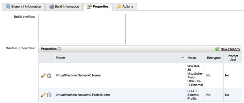
On-Demand Infrastructure
                                                                                with Secure Networks

Executive Summary
This reference architecture showcases the integrations between VMware vCloud® Suite Enterprise,
VMware NSX™ for vSphere®, and VMware vCenter™ Log Insight™ to create an on-demand infrastructure with
a secure networking environment. It is based on real-world scenarios, user workloads, and infrastructure
system configurations. It uses industry-standard servers, IP-based storage, and 10-Gigabit Ethernet (10GbE)
networking to support a scalable and redundant architecture based on vCloud Suite Enterprise version 5.5.
An overview of the solution and the logical architecture as well as results of the tested physical implementation
are provided. Consult with your VMware representative as to how to modify the architecture to suit your
business needs.

Audience
This document will assist enterprise architects, solution architects, sales engineers, field consultants, advanced
services specialists, and customers who are responsible for infrastructure services. This guide provides an
example of a successful deployment of an on-demand infrastructure with secure networking compliant with
existing policies.

Overview
As companies begin to investigate a software-defined data center (SDDC), the inefficiencies of traditional
architectures become readily apparent. The SDDC requires IT architects to take a step back and look at the
infrastructure in a new way. Automation plays a key role in this new era of the data center. Gone are the days
when users submitted a ticket and waited for their machine to be manually provisioned. More and more, users
expect to have a predefined list of services available to them and to have these services created instantly upon
request. IT is still required to control and secure these machines. This reference architecture addresses these
needs by providing users with the on-demand access they want while ensuring that IT keeps the control and
security it requires.

                                                                                  TECH N I C AL WH ITE PAPE R / 3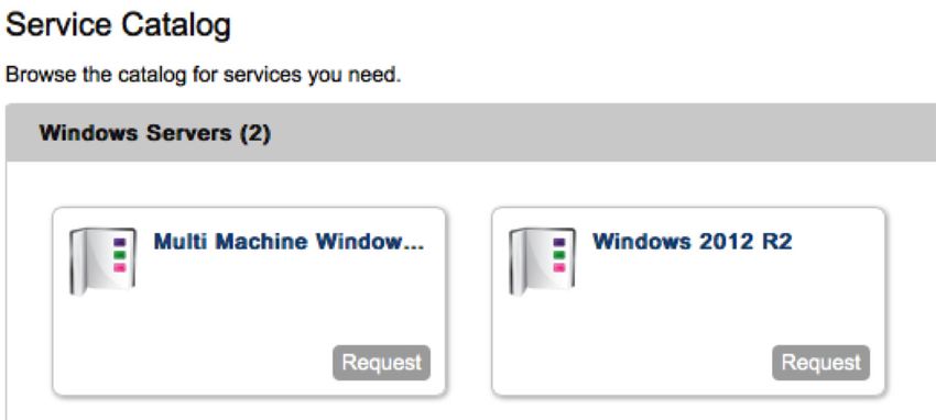
On-Demand Infrastructure
                                                                                  with Secure Networks

What Is an On-Demand Infrastructure with
Secure Networks?
An on-demand infrastructure with secure networks is a solution that enables rapid provisioning of compute
workloads along with any required networking services. The design delivers a comprehensive solution that
enables customers to provision the infrastructure they require from a self-service portal and to manage its
entire lifecycle.

    Secure user portal                     Entitled users utilizing a Web-based portal can request IT services—
                                           known as “blueprints”—from a service catalog .

    Blueprints                             Blueprints define the attributes associated with items in the service
                                           catalog. These items might include virtual, physical, or cloud machines
                                           as well as other IT services such as load balancers, firewall rules, runtime
                                           policies, and billing policies.

    Security groups                        Security groups enable administrators to specify rules to control
                                           network traffic over particular ports. An administrator specifies security
                                           groups when creating resources in VMware vCloud Automation Center™.

    Distributed firewall                   NSX for vSphere provides a distributed firewall service that operates at
                                           the VMware ESXi™ kernel level. This enables firewall rule enforcement in
                                           a highly scalable manner without creating bottlenecks common to
                                           physical and virtual firewall appliances. With this reduced overhead, the
                                           service can perform at true line rate with minimal CPU overhead.

    Logical routing –                      The distributed routing capability in the NSX for vSphere platform
    Distributed routing                    provides an optimized and scalable way of handling traffic between
                                           virtual machines or other resources within the data center.
                                           Traditionally, virtual machines connected to different subnets must
                                           communicate with one another through an external router. In this
                                           manner, all virtual machine–to–virtual machine communication crossing
                                           subnets must pass through a router.
                                           The distributed routing on the NSX for vSphere platform prevents this
                                           traditional unoptimized traffic flow by providing hypervisor-level routing
                                           functionality. Each hypervisor has a routing kernel module that performs
                                           routing between the logical interfaces (LIFs) defined on that distributed
                                           router instance.

    Logical switching                      The logical switching capability in the NSX for vSphere platform enables
                                           users to spin up isolated logical L2 networks with the same flexibility and
                                           agility they have had with virtual machines.

    Extensibility                          vCloud Automation Center provides out-of-the-box integration with
                                           VMware vCenter Orchestrator™ and many third-party solutions.

Table 1. Key Features of This Solution

                                                                                     TECH N I C AL WH ITE PAPE R / 4
On-Demand Infrastructure
with Secure Networks
Architecture Overview
This architecture utilizes three different clusters—the management cluster, the edge cluster, and the payload
cluster—to achieve the preferred outcome.
The management cluster consists of a minimum of three ESXi hosts. It contains all of the components used to
manage the virtual infrastructure, including but not limited to VMware vCenter Server™, vCloud Automation
Center, VMware vCenter Operations Manager™, VMware NSX Manager™, vCenter Log Insight, Microsoft Active
Directory domain controllers, and database servers. The management cluster is logically isolated from the other
clusters and is directed by a dedicated vCenter Server instance.
The edge cluster consists of a minimum of three ESXi hosts. It contains the NSX for vSphere components and it
hosts NSX for vSphere networking services. The edge cluster provides all external connectivity to the payload
clusters.
The payload clusters are a minimum of 3 and a maximum of 32 ESXi hosts; this is where end-user virtual
machines run. The vCenter Server instance that manages the edge cluster and payload cluster resides within the
management cluster. Additional payload clusters can be added until the maximum for any one component is
reached, at which time the architecture can be repeated.
vCenter Server Central platform for managing and configuring the ESXi hypervisor.
VMware vSphere Web Client is the centralized point of administration
for compute clusters and all networking services provided by
NSX for vSphere.
vCloud Suite Enterprise Comprehensive suite of products used to deliver the SDDC. In this
architecture, users leverage the following components of the
vCloud Suite Enterprise, VMware vSphere® Enterprise Plus Edition™,
vCloud Automation Center, vCenter Orchestrator, and
vCenter Operations Manager.
NSX for vSphere NSX for vSphere exposes a complete suite of simplified logical
networking elements and services including logical switches, routers,
firewalls, load balancers, virtual private network (VPN), QoS, monitoring,
and security.
vCenter Log Insight Real-time log management and log analysis with machine learning–
based intelligent grouping, high-performance search, and better
troubleshooting across physical, virtual, and cloud environments.
Table 2. Components
TECH N I C AL WH ITE PAPE R / 5On-Demand Infrastructure
with Secure Networks
Management Cluster
Common Components
Active SQL Cluster vCenter Log Insight
Directory Operations
Manager
Management Cluster Components
NSX for NSX for Logical
vCenter vSphere Manager vSphere Router
Controllers
Load Distributed vFabric
NSX Edge Balancers Firewall Postgres
vCloud vCloud vCloud vCenter
Automation Center Automation Center Automation Center
Appliances Orchestrator
IaaS Web IaaS Managers
Edge and Payload Cluster Components
NSX for vCenter
vCenter vSphere Manager Orchestrator
Figure 1. Management Cluster Components
TECH N I C AL WH ITE PAPE R / 6On-Demand Infrastructure
with Secure Networks
Corporate Internet
Network
Edge Cluster Payload Cluster(s)
Distributed Logical Router
Distributed Firewall
NSX for vSphere Logical Switches
NSX for vSphere Edge Services (North–South Routing, NAT, Load Balancing, etc.)
NSX for vSphere Logical Router Control Virtual Machine
NSX for vSphere Controller
Figure 2. NSX for vSphere Logical Architecture
TECH N I C AL WH ITE PAPE R / 7On-Demand Infrastructure
with Secure Networks
Corporate Internet
Network
VM
VXLAN
Distributed Firewall Distributed Firewall
Distributed Logical Router
Management Edge Payload
vCenter vCenter
NSX for vSphere
vCenter Orchestrator
NSX for vSphere
vCloud Automation Center
vCenter Operations Manager
vCenter Log Insight
Figure 3. Wire Map
Cluster Overview
This design uses three cluster types, each with its own distinct function. It provides a management plane that is
separate from the user workload virtual machines. In addition, it leverages an edge cluster, which provides
dedicated compute resources for network services such as load balancers and edge routers; these provide
access to the corporate network and the Internet. This design simplifies the network configuration by eliminating
the need to trunk a large number of VLANs to all hosts. Virtual machine–to–virtual machine and virtual
machine–to–edge traffic utilizes the NSX for vSphere distributed logical router, which is implemented as a kernel
module in each ESXi host. Virtual machines are secured on the network, using the NSX for vSphere distributed
firewall, which is also implemented as a kernel module. This enables firewall rules to be enforced before any
traffic is put on the wire.
Management Cluster
The management cluster contains the management and monitoring solutions for the entire design. A single
management cluster can support multiple pods of edge and payload clusters. The minimum number of hosts
required is three, but it will scale out as the number of edge and payload ESXi hosts increases.
A single vCenter Server instance manages the resources in the management cluster. Additional vCenter Server
instances are used to manage edge and payload clusters.
TECH N I C AL WH ITE PAPE R / 8On-Demand Infrastructure
with Secure Networks
The management cluster also contains common core infrastructure. This includes Active Directory, a Microsoft
SQL Server cluster, vCenter Operations Manager, and vCenter Log Insight.
NSX Manager instances, one for each vCenter Server, are deployed into the management cluster. NSX for vSphere
components, such as VMware NSX Controller™ instances, are also deployed for and in the management cluster.
All vCloud Automation Center components are also deployed in the management cluster.
Edge Cluster
The edge cluster simplifies physical network switch configuration. It is used to deliver networking services to
payload-cluster (user-workload) virtual machines. All external networking, including corporate and Internet, for
user-workload virtual machines is accessed via the edge cluster. The minimum cluster size is three hosts, but it
can scale depending on the volume of edge services required by payload-cluster virtual machines.
Payload Clusters
The payload clusters are the simplest of the three types; they run user-workload virtual machines. Payload-
cluster networking is completely virtualized using NSX for vSphere. A single transport zone exists between all
payload clusters and the edge cluster. A single NSX for vSphere distributed logical router exists between all
clusters. This gives any virtual machine on any host the ability to communicate with any other virtual machine on
any host in any cluster—if NSX for vSphere distributed firewall rules permit—without incurring any layer 3 routing
penalties. The ESXi host handles all layer 3 routing decisions. When traffic must leave a host, it is encapsulated in
an NSX for vSphere packet and sent to the destination host via layer 2, where the destination host delivers the
packet to the destination virtual machine.
Physical Component Details
Compute
The following table lists the recommended physical server configuration:
COMPONENT S P E C I F I C AT I O N
CPU 24GHz – 2 x 2.0GHz six-core CPUs (12 total cores)
Memory 128GB ECC RAM
Internal storage 6GB SD card boot device
Network interface cards 2 x 10Gb
Power supplies Redundant
Fans Redundant
Table 3. Component Specifications
All physical server hardware, regardless of cluster, utilizes the same configuration, for ease of management and
to guarantee resource availability as the solution grows. For large deployments, each cluster type should be
placed into its own rack with its own top-of-rack switches. This is discussed in detail in the “Network” section.
TECH N I C AL WH ITE PAPE R / 9On-Demand Infrastructure
with Secure Networks
Storage
The management cluster utilizes two 500GB NFS datastores in addition to one 10GB and one 50GB iSCSI RDM.
The NFS storage serves all management virtual machines; the iSCSI RDMs are used to support the shared-
storage requirement of a Microsoft SQL Server cluster.
The edge cluster utilizes two 500GB NFS datastores. These datastores serve the NSX Controller instances for
the edge and payload clusters as well as for all VMware NSX Edge™ devices.
The payload clusters utilize at least two NFS datastores. The size and number depend on user application I/O
needs. Two 500GB datastores are used for this reference architecture.
Clusters SAN/NAS
Management
500 500
GB GB
10 50
Edge GB GB
500 500
Payload GB GB
500 500
GB GB NFS
iSCSI RDM
Figure 4. Storage
Network
Each rack contains a pair of 10GbE top-of-rack switches. Each host has one 10GbE port connected to each
top-of-rack switch; the switches are configured to provide a virtual Link Aggregation Control Protocol (LACP)
port channel, which the host detects as a connection to a single switch. This enables maximum bandwidth usage
and redundancy.
802.1.Q trunks are used for carrying a small number of VLANs—for example, NSX for vSphere, management,
storage, and VMware vSphere vMotion® traffic. The switch terminates and provides default gateway functionality
for each respective VLAN; that is, it has a switch virtual interface (SVI) for each VLAN. Uplinks from the top-of-
rack switch to the aggregation layer are routed point-to-point links. VLAN trunking on the uplinks—even for a
single VLAN—is not allowed. A dynamic routing protocol (OSPF, ISIS, or BGP) is configured between the top-of-
rack and aggregation layer switches. Each top-of-rack switch in the rack advertises a small set of prefixes,
typically one per VLAN or subnet that is present. In turn, it will calculate equal cost paths to the prefixes received
from other top-of-rack switches.
TECH N I C AL WH ITE PAPE R / 1 0On-Demand Infrastructure
with Secure Networks
Aggregate Layer
OSPF
Provides default gateway for all VLANs.
Access Layer VLANs are not trunked to aggregate layer switches.
10GbE
Virtual Port Channel
VMware ESXi Host
Figure 5. Physical Network Connections
Software-Defined Data Center Component Details
In this section, we will define the VMware software components and their configuration in enabling this solution.
Unless otherwise stated, all Microsoft Windows installations utilize Windows Server 2012 R2 Standard Edition.
Because this architecture utilizes the Failover Clustering feature, Microsoft SQL Server Enterprise Edition 2012
SP1 is required.
vSphere Data Center Logical Design
The vSphere Enterprise Plus Edition platform is the core that enables the SDDC. All ESXi hosts are stateful
installs—that is, the ESXi hypervisor is installed to local disks.
AT T R I B U T E S P E C I F I C AT I O N
ESXi version 5.5; Build: 1892794
Number of hosts 3
Number of CPUs per host 2
Number of cores per CPU 8
Core speed 2.0GHz
Memory 128GB
Number of network adapters Two 10Gb
Table 4. Management Cluster Details
TECH N I C AL WH ITE PAPE R / 11On-Demand Infrastructure
with Secure Networks
The cluster leverages VMware vSphere High Availability (vSphere HA) and VMware vSphere Distributed
Resource Scheduler™ (vSphere DRS). vSphere HA is set to monitor both hosts and virtual machines. Its
admission control policy utilizes a percentage of cluster resources reserved—in this configuration, 33 percent—
guaranteeing sustainability with one node failure. vSphere DRS is set to fully automated mode.
VLAN ID FUNCTION
970 ESXi management
1020 IP storage (NFS/iSCSI)
1060 Virtual machine management (vCenter, SQL, etc.)
Table 5. Management Cluster Virtual Switch Port Groups and VLANs
The VLANs must terminate on the top-of-rack switch, provide default gateway services, and utilize dynamic
routing between the top-of-rack switch and the aggregation-layer switch.
I P S TO R AG E FUNCTION
NFSMGT01 500GB management virtual machine datastore
NFSMGT02 500GB management virtual machine datastore
Physical RDM 1 10GB RDM in physical compatibility mode –
Microsoft Cluster Service (MSCS) quorum
Physical RDM 2 50GB RDM in physical compatibility mode
(clustered shared SQL data)
Table 6. Management Cluster Storage
AT T R I B U T E S P E C I F I C AT I O N
Number of CPUs 4
Processor type VMware virtual CPU
Memory 16GB
Number of network adapters 1
Network adapter type VMXNET3
Number of disks 3
30GB (C:\) – VMDK
10GB (Q:\) – RDM (physical mode)
50GB (D:\) – RDM (physical mode)
Operating system Windows Server 2012 R2
Table 7. SQL Cluster Server Configuration
For more information on how to configure Microsoft Cluster Service (MSCS) in a vSphere environment, see
VMware Knowledge Base article 1037959 and the setup for Microsoft clustering guide.
TECH N I C AL WH ITE PAPE R / 12On-Demand Infrastructure
with Secure Networks
AT T R I B U T E S P E C I F I C AT I O N
vCenter version vCenter Server 5.5 Update 1c installable
Operating system Windows Server 2012 R2
Quantity 2 (1 for management cluster, 1 for edge and payload clusters)
Number of CPUs 4
Processor type VMware virtual CPU
Memory 16GB
Number of network adapters 1
Network adapter type VMXNET3
Number of disks 1
100GB (C:\) – VMDK
Table 8. VMware vCenter Configuration
To increase database resiliency, database clustering via Microsoft SQL is used. To use SQL and the Linked Mode
feature of vCenter, the Windows installable version of vCenter must be used.
The following components are also installed on the vCenter Server instance as part of the vCenter installation
process. All components requiring an SQL database—that is, vCenter Server and VMware vSphere Update
Manager™—must have their databases located on the SQL cluster.
COMPONENT DESCRIPTION
VMware vCenter Single Sign-On™ Authentication broker service.
vSphere Web Client Web version of VMware vSphere Client™ used to manage
vSphere. The vSphere Web Client is the only way to configure
new features of vSphere 5.5 and later.
vCenter Inventory Service vCenter Inventory Service is used to manage the vSphere
Web Client inventory objects and property queries that the
client requests when users navigate the vSphere
environment.
vCenter Server vCenter Server is the main component that enables the
centralized management of all ESXi hosts and the virtual
machines that run on those ESXi hosts.
VMware vSphere Update Manager™ vSphere Update Manager automates patch management and
eliminates manual tracking and patching of vSphere hosts.
Table 9. VMware vCenter Components
AT T R I B U T E S P E C I F I C AT I O N
Data center object WDC
Linked Mode Enabled
Table 10. VMware vCenter Data Center Configuration
TECH N I C AL WH ITE PAPE R / 13On-Demand Infrastructure
with Secure Networks
PORT GROUP VLAN ID FUNCTION
HostMGMT 970 ESXi management
vMotion 980 vSphere vMotion
Storage 1020 IP storage (NFS/iSCSI)
Table 11. Management Cluster Virtual Switch Port Groups and VLANs
AT T R I B U T E S P E C I F I C AT I O N
ESXi version 5.5; Build: 1892794
Number of hosts 3
Number of CPUs per host 2
Number of cores per CPU 8
Core speed 2.0GHz
Memory 128GB
Number of network adapters 2 10Gb
Table 12. Edge Cluster Details
The cluster leverages vSphere HA and vSphere DRS. vSphere HA is set to monitor both hosts and virtual machines
with its admission control policy set to a percentage of cluster resources reserved—33 percent for a three-node
cluster—guaranteeing the sustainability of one node failure. vSphere DRS is set to fully automated mode.
AT T R I B U T E S P E C I F I C AT I O N
ESXi version 5.5; Build: 1892794
Number of hosts 4
Number of CPUs per host 2
Number of cores per CPU 8
Core speed 2.0GHz
Memory 128GB
Number of network adapters 2 10Gb
Table 13. Payload Cluster Details
TECH N I C AL WH ITE PAPE R / 14On-Demand Infrastructure
with Secure Networks
The cluster leverages vSphere HA and vSphere DRS. vSphere HA is set to monitor both hosts and virtual machines
with its admission control policy set to a percentage of cluster resources reserved—25 percent for a four-node
cluster—guaranteeing the sustainability of one node failure. vSphere DRS is set to fully automated mode.
PORT GROUP VLAN ID FUNCTION
HostMGMT 970 ESXi management
vMotion 980 vSphere vMotion
Storage 1020 IP storage (NFS/iSCSI)
External 2010 External connectivity to
corporate network
Table 14. VMware vSphere Distributed Switch Port Groups and VLANs
vSphere Distributed Switch
Uplinks
Top-of-Rack
VLANs/SVI
970 – 10.10.70.x
980 – 10.10.80.x
1020 – 10.10.120.x
HostMGMT 1060 – 10.10.160.x
VLAN 970 2010 – 10.10.210.x
(2010 is on NSX Edge rack
switches only.)
vMotion
VLAN 980
Storage
VLAN 1020
VMMGMT
VLAN 1060
External
VLAN 2010
Figure 6. VLANs and SVI
The external port group is configured with one static port with the elastic option disabled; an NSX Edge device is
all that is connected to this port group. The remaining ports are configured with static binding with the default
eight ports and the elastic option enabled.
The uplink configuration should be set up using a link aggregation group (LAG) utilizing the LACP with a hashing
algorithm that is compatible with the physical switches.
vCenter Orchestrator
vCenter Orchestrator was deployed using the vCenter Orchestrator appliance. For resiliency, it was set up in a
cluster, with its database residing on the SQL cluster.
TECH N I C AL WH ITE PAPE R / 15On-Demand Infrastructure
with Secure Networks
NSX for vSphere
NSX for vSphere provides all the logical switches, routing, and distributed firewall services used to create this
architecture. Service for all virtual machine traffic, excluding management cluster, is encapsulated using
NSX for vSphere. All virtual machine–to–virtual machine, or east–west, traffic is routed between hosts by the
NSX for vSphere distributed logical router. When a request to or from the external network is serviced, it travels
through an NSX Edge device, which provides all north–south routing—that is, routing to and from external
networks.
NSX for vSphere has a one-to-one relationship with vCenter Server, so two NSX Manager instances were
deployed, one for the management cluster vCenter Server instance and the other for the edge- and payload-
cluster vCenter Server instance. These were both deployed in the management cluster.
NSX for vSphere utilizes controller virtual machines to implement the network control plane. The NSX Controller
instances must be deployed in odd numbers to avoid a split-brain scenario. As such, three controllers per
NSX for vSphere instance are deployed, with vSphere DRS rules set up to ensure that they not run on the same
host. The NSX Controller instances for the management cluster are deployed into the management cluster itself.
The NSX Controller instances for the edge and payload clusters are deployed into the edge cluster.
The ESXi hosts must be prepared for NSX for vSphere. The following values are used:
S P E C I F I C AT I O N VA LU E
MTU 9000
Teaming mode LACP –
active mode
Segment IDs 5000-7999
Transport zones 1 – encompassing all clusters
Table 15. NSX for vSphere Host Preparation Values
Internal (east–west) routing is enabled using the NSX for vSphere distributed logical router. With it, all ESXi hosts
can communicate with other ESXi hosts—assuming that firewall rules allow—via layer 3, with no need to access
an external router. In this configuration, each ESXi host running the distributed router acts as the default gateway
for virtual machines on the host. Virtual machines communicate with the host on which they are currently
running, which then encapsulates the traffic in the NSX for vSphere overlay and sends it to the destination host,
where the packets are decapsulated and delivered to the correct destination. This distributed routing eliminates
the need to hop to an external router to communicate with virtual machines on different subnets.
TECH N I C AL WH ITE PAPE R / 1 6On-Demand Infrastructure
with Secure Networks
ESXi Host 1 ESXi Host 2 ESXi Host 3
192.168.1.1 192.168.1.1 192.168.1.1
192.168.2.1 192.168.2.1 192.168.2.1
Distributed Logical Router
Logical Switch 1 – Gateway 192.168.1.1
NSX Edge (HA)
Distributed Logical Router Logical Switch 2 – Gateway 192.168.2.1
(Control Plane)
Virtual Virtual
Machine 1 Machine 2
192.168.1.10 192.168.2.10
Figure 7. NSX for vSphere East–West Routing
To enable external (north–south) connectivity, we deploy an NSX Edge router in HA mode. One interface is
connected to the external network; another is connected to a logical switch, which is also connected to the
NSX for vSphere distributed logical router. Both the NSX Edge device and the distributed logical router run the
OSPF dynamic routing protocol to propagate routing information upstream to the physical network and also
downstream to the NSX for vSphere distributed logical router.
Top-of-Rack Switch
OSPF
NSX Edge Router (HA)
ESXi Host 1 ESXi Host 2 ESXi Host 3
Distributed Logical Router OSPF
Logical Switch 1 – Network 192.168.1.0/24
Logical Switch 2 – Network 192.168.2.0/24
NSX Edge (HA)
Distributed Logical Router Logical Switch 3 – Transit Network 10.1.1.0/24
(Control Plane)
Figure 8. NSX for vSphere North–South Routing
TECH N I C AL WH ITE PAPE R / 17On-Demand Infrastructure
with Secure Networks
By default, the distributed firewall—which like the distributed logical router is a kernel module on the ESXi
hosts—allows all traffic. This enables the rules to be evaluated and decisions to be made in real time before a
packet is placed on the network. There are several ways to create firewall rules. In this architecture, we created
security groups based on security tags. The appropriate firewall rules were created in the service composer and
assigned to the security group. This automates the firewall rules applied to virtual machines as they are added or
removed from security groups. The following security tags, groups, and rules were created for the vCloud
Automation Center servers.
S E C U R I T Y TAG SECURIT Y SERVER ROLE INBOUND OUTBOUND
GROUP PORTS PORTS
vCloud Automation vCloud Automation vCloud Automation HTTPS: 443 SSO: 7444
Center appliances Center appliances Center virtual VAMI: 5480 vPostgres virtual
appliances SSH: 22 appliances: 5432
vCloud Automation
Center IaaS Web
load balancer: 443
vCenter
Orchestrator: 8281
VMware vFabric vPostgres servers vPostgres virtual vPostgres: 5432
Postgres® servers appliance SSH: 22
vCloud Automation vCloud Automation Infrastructure Web HTTPS: 443 MSSQL: 1433
Center IaaS Web Center IaaS Web server RDP: 3389
vCloud Automation vCloud Automation Infrastructure HTTPS: 443 vCloud Automation
Center IaaS Center IaaS manager servers RDP: 3389 Center IaaS Web
managers managers load balancer: 443
MSSQL: 1433
vCloud Automation vCloud Automation Infrastructure DEM RDP: 3389 Identity VA: 7444
Center DEMs Center DEMs server vCloud Automation
Center appliances
load balancer: 443
vCloud Automation
Center IaaS Web
load balancer: 443
vCloud Automation
Center IaaS
managers load
balancer: 443
vCloud Automation vCloud Automation Infrastructure RDP: 3389 vCloud Automation
Center IaaS agents Center IaaS agents agent server Center IaaS Web
load balancer: 443
vCloud Automation
Center IaaS
managers load
balancer: 443
MSSQL MSSQL Microsoft SQL MSSQL: 1433
Database Server RDP: 3389
Table 16. Security Tags, Groups, and Rules for vCloud Automation Center Servers
TECH N I C AL WH ITE PAPE R / 1 8On-Demand Infrastructure
with Secure Networks
vCloud Automation Center
vCloud Automation Center provides the portal to the business users who will be requesting services. This
architecture uses NSX for vSphere to load-balance incoming requests to highly available instances of the
vCloud Automation Center components.
vCloud Automation Center
Appliance, Web,
and Manager VIPs
VLAN 1060
vFabric vCloud vCloud vCloud vCloud vCloud vCloud vCloud vCloud
Postgres Automation
Center
Automation
Center
Automation
Center
Automation
Center
Automation
Center
Automation
Center
Automation
Center
Automation
Center
Appliance Appliance Web 1 and Web 2 Manager Active Manager Passive DEM DEM
NSX Edge (HA) 1 2 Model Manager
One-Armed
Load Balancer
vPostgres Servers vCloud vCloud vCloud vCloud
Security Group Automation Center Automation Center Automation Center Automation Center
Appliances Security Group IaaS Web Security Group IaaS Managers Security Group DEMs Security Group
Figure 9. Load-Balanced vCloud Automation Center Configuration
To achieve the architecture shown in Figure 9, we deployed a single NSX Edge device in HA mode. It was
configured to load-balance the vCloud Automation Center appliance, Web, and vCloud Automation Center
manager traffic. To achieve the preferred distributed firewall configuration, the NSX for vSphere security tags
and groups discussed in the previous section were also created and applied to each virtual machine after they
were built.
Because we are load balancing all traffic except the distributed execution managers, a registry setting that
disables Windows loopback checking was created. See VMware Knowledge Base article 2053365 for more
information.
vCloud Automation Center Appliances
The vCloud Automation Center appliance is distributed as a prepackaged appliance in OVA format. For increased
redundancy, two of these appliances were deployed and configured for clustering, along with an external
vFabric Postgres master–slave cluster. The NSX Edge device shown in Figure 9 is configured to load-balance the
traffic to the vCloud Automation Center appliances. The two servers share a common SSL certificate with the
fully qualified domain name (FQDN) of the load balancer virtual IP.
vSphere DRS rules were created to ensure that the vCloud Automation Center appliances run on different hosts;
similarly, vSphere DRS rules were also created for the vFabric Postgres cluster nodes, to ensure that they also
run on different hosts.
vCloud Automation Center IaaS Web Servers
The vCloud Automation Center IaaS Web servers run on Windows. Because of the dependency on the .NET
framework version, Windows 2012 was used. For redundancy, two IaaS Web servers were deployed. Both are
active and are load balanced by the NSX Edge device shown in Figure 9. The model manager data is deployed to
the first IaaS Web server only. The two servers share a common SSL certificate with the FQDN of the load
balancer virtual IP.
TECH N I C AL WH ITE PAPE R / 1 9On-Demand Infrastructure
with Secure Networks
vCloud Automation Center IaaS Managers
The vCloud Automation Center IaaS manager runs on Windows. Because of the dependency on the .NET
framework version, Windows 2012 was used. For redundancy, two IaaS managers were deployed. Only one is set
to active; the other is passive. The NSX Edge device shown in Figure 9 is configured to load-balance the traffic,
but only the currently active manager is active on the load balancer. During an outage, manual steps are taken to
make the passive server active and to update the load balancer configuration to use the now-active server. The
two servers share a common SSL certificate with the FQDN of the load balancer virtual IP.
Distributed Execution Managers and the vSphere Agent
The distributed execution manager (DEM) and the vSphere agent run on Windows. Because of the dependency
on the .NET framework version, Windows 2012 was used. The DEM and the vSphere agent were installed on a
pair of servers; they do not support load balancing but are highly available when deployed in this configuration.
Monitoring
Monitoring the performance, capacity, health, and logs in any environment is critical. But in a solution where IT
gives some control to the business users, monitoring becomes mission critical to the success of user adoption.
vCenter Operations Manager
vCenter Operations Manager provides operations dashboards, performance analytics, and capacity optimization
capabilities needed to gain comprehensive visibility, proactively ensure service levels, and manage capacity in
dynamic virtual and cloud environments.
vCenter Operations Manager is deployed as a pair of virtual appliances in a VMware vSphere vApp™ distributed
in the OVA format. A network protocol profile is created and assigned to the port group the virtual appliances
are attached to. vCloud Automation Center was deployed in the large configuration to support this architecture.
To ensure a complete picture of how the environment is running, vCenter Operations Manager is configured to
monitor the management, edge, and payload vCenter Server instances.
vCenter Operations Manager requires updates to the default monitoring settings of most organizations. For
more information on how to customize vCenter Operations Manager for your specific environment, see the
vCenter Operations Manager documentation.
vCenter Log Insight
vCenter Log Insight provides in-depth log analysis in an easy-to-query Web interface. It collects syslog data
from ESXi hosts or any other server or device that supports syslog. There is also an installable agent for
Windows that enables the collection of event logs and custom logs such as the vCenter Server log files.
vCenter Log Insight is deployed as a virtual appliance. During the deployment, the large size was chosen.
The Windows agent is installed on the vCenter Server instance and on vCloud Automation Center servers to
collect their log files.
The syslogs of all appliances and ESXi hosts were configured to send to the vCenter Log Insight server.
TECH N I C AL WH ITE PAPE R / 20On-Demand Infrastructure
with Secure Networks
vCloud Automation Center Operational
Configuration
When all of the components have been installed, they must be brought together to enable the creation of
blueprints and the provision of services by authorized users. To unify the components to operate as a solution,
the following configuration steps are required.
NSX for vSphere Configuration
First we provision the common network resources for use within vCloud Automation Center. An NSX Edge
device in the edge cluster was created for north–south routing; the OSPF dynamic routing protocol was
configured between the NSX Edge device and the external physical switches. The distributed logical routing
functionality was also enabled in both the edge and payload clusters for east–west routing with dynamic routing
via OSPF between the NSX Edge device and the distributed logical router. Logical switches were precreated for
use in vCloud Automation Center for single-machine blueprints; they were connected to the distributed logical
router. vCloud Automation Center can dynamically create logical switches in multimachine blueprints.
Tenants
A tenant is an organizational unit in a vCloud Automation Center deployment. A tenant can represent the entire
organization or specific business units. There is a default vsphere.local tenant created during the installation.
This tenant is the only tenant that can leverage native Active Directory integration; all other tenants must bind to
an Active Directory domain controller as an LDAP server. Because of this limitation and the fact that we can have
resource reservations at a business-group level—this will be discussed later—this architecture utilizes only the
default tenant.
Endpoints
Endpoints are the infrastructure sources that vCloud Automation Center consumes. In vCloud Suite and in this
architecture, the endpoint is vCenter Server—more specifically, the vCenter Server instance that manages the
edge and payload clusters.
Fabric Groups
Fabric groups are groups of compute resources that the endpoints discover; they define the organization of
virtualized compute resources. In most single-site environments, a single fabric group is created that contains all
nonmanagement clusters.
Business Groups
Business groups define the users and machine prefix and are used later to grant access to a percentage of
resources. Users assigned the group manager role can create blueprints and see all machines created in the
group. Support users can work for another user, and users can be entitled to request blueprints in the catalog.
In most environments, business groups are created for department or business units in an organization.
Network Profiles
Network profiles define the type of connection—external, private, NAT, or routed—that a resource has. NAT and
routed profiles require an external profile. External profiles connect resources to an existing network.
TECH N I C AL WH ITE PAPE R / 21On-Demand Infrastructure
with Secure Networks
Reservation Policies
Reservation policies enable a user to associate one or more reservations into a policy that can be applied to a
blueprint. Multiple reservations can be added to a reservation policy, but a reservation can belong to only one
policy. A single reservation policy can be assigned to more than one blueprint. A blueprint can have only one
reservation policy.
Reservations
A virtual reservation is a share of the memory, CPU, networking, and storage resources of one compute resource
allocated to a particular business group.
To provision virtual machines, a business group must have at least one reservation on a virtual compute
resource. Each reservation is for one business group only, but a business group can have multiple reservations
on a single compute resource or on compute resources of different types.
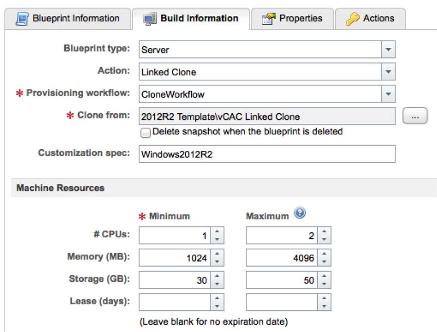
Blueprints
A machine blueprint is the complete specification for a virtual, cloud, or physical machine. Blueprints determine
a machine’s attributes, the manner in which it is provisioned, and its policy and management settings.
In this architecture, blueprints can be either vSphere based—that is, single machine—or multimachine, which
requires one or more vSphere blueprints and provisions and manages them together as a single entity.
Multimachine blueprints also enable the dynamic provisioning of networks using network profiles.
Figure 10. Blueprint Information
TECH N I C AL WH ITE PAPE R / 2 2On-Demand Infrastructure
with Secure Networks
Figure 11. Blueprint Build Information
By default, the blueprint will be provisioned onto the same network as the template. Custom properties can be
specified to choose the network and network profile among other settings for the blueprint to use.
Figure 12. Blueprint Custom Properties
After blueprints have been created and published to the catalog, authorized users can log in to the
vCloud Automation Center portal and request these resources.
TECH N I C AL WH ITE PAPE R / 2 3On-Demand Infrastructure
with Secure Networks
Figure 13. vCloud Automation Center Service Catalog
About the Authors
Mike Brown is a senior technical marketing manager in the Cloud Infrastructure Technical Marketing group.
Mike’s focus is on reference architectures for VMware vCloud Suite and the software-defined data center as well
as on resource management. He has multiple industry certifications, including VMware Certified Design Expert
(VCDX). Follow Mike on the vSphere Blog and on Twitter @vMikeBrown.
Matthew Meyer is a senior technical marketing architect focused on developing reference architectures for the
software-defined data center powered by VMware vCloud Suite. Matthew has more than 10 years of experience with
VMware technologies and holds several industry certifications, including VMware Certified Design Expert (VCDX).
TECH N I C AL WH ITE PAPE R / 24VMware, Inc. 3401 Hillview Avenue Palo Alto CA 94304 USA Tel 877-486-9273 Fax 650-427-5001 www.vmware.com Copyright © 2014 VMware, Inc. All rights reserved. This product is protected by U.S. and international copyright and intellectual property laws. VMware products are covered by one or more patents listed at http://www.vmware.com/go/patents. VMware is a registered trademark or trademark of VMware, Inc. in the United States and/or other jurisdictions. All other marks and names mentioned herein may be trademarks of their respective companies. Item No: VM-RA-OD-Infra-Scr-Ntwks-USLET-101 Docsource: OIC-FP-1190
You can also read