Nuclear Engineering and Design
←
→
Page content transcription
If your browser does not render page correctly, please read the page content below
Nuclear Engineering and Design 404 (2023) 112173
Contents lists available at ScienceDirect
Nuclear Engineering and Design
journal homepage: www.elsevier.com/locate/nucengdes
PANDA experimental database and further needs for containment analyses
Domenico Paladino a, *, Ralf Kapulla a, Sidharth Paranjape b, Simon Suter a, Christoph Hug a,
Myeong-Seon Chae a, Michele Andreani a
a
Paul Scherrer Institut, Forschungsstrasse 111, 5232 Villigen PSI, Switzerland
b
OST – Ostschweizer Fachhochschule Departement Technik, 9471 Buchs, Switzerland
A B S T R A C T
PANDA is a large-scale, multi-compartment, thermal-hydraulics facility located at the Paul Scherrer Institute (PSI) in Switzerland and is operated for nuclear safety
projects. PANDA is continuously upgraded with new components and instruments to meet the requirements of each new project. The modularity of the facility and its
instrumentation provide unique opportunities to perform experiments ranging from basic containment phenomena studied mainly in a single vessel to integral
behavior of Passive Containment Cooling Systems (PCCS) requiring up to six PANDA vessels and four passive condensers (PCCs, IC) submerged in four water pools.
Experimental data analyses are performed using system codes, lumped parameter (LP) severe accident codes and Computational Fluid Dynamics (CFD) codes. In this
paper, we provide an overview of the PANDA experimental database and identify further data needs for containment analyses, considering the main results of
recently completed PANDA projects.
1. Introduction during postulated accident relaying on natural circulation (Upton et al.,
1996; Gamble et al., 2001).
PANDA (Yadigaroglu and Dreier, 1988) is a large scale thermal The SBWR design was tested in a framework of joint efforts from PSI,
–hydraulic facility at PSI in Switzerland and is operated for safety- EPRI, GE and the Swiss Utilities (Paladino and Dreier, 2012b). The
related research investigations (Sehgal, 2012) for existing nuclear re SWR1000 design (new name for SWR1000 is KERENA (Mull et al.,
actors as well as for new reactor designs. 2022)) was experimentally investigated in the IPPS Project (EURATOM
In this article, we provide a description of the PANDA and an over 4th FWP) (Dreier et al., 1999). The ESBWR was first tested in the TEPSS
view of the PANDA projects. We also describe the PANDA experimental Project (EURATOM 4th FWP) (Huggenberger et al., 1999; Bandurski
database in term of phenomena studied and the methodology used to et al., 2001). Later, the effect of hydrogen on passive systems was
define the PANDA experiments related to specific reactor concepts. investigated in the TEMPEST Project (EURATOM 5th FWP) (Paladino
Based on the results of the recently completed OECD/NEA HYMERES et al., 2011). In the TEMPEST project, PANDA tests investigated also the
phase 2 project (Paladino et al., 2022a), we outline the further need for effect on the PCCS of the Drywell Gas Recirculation System (DGRS)
experimental data for containment safety analyses. during a LOCA (Paladino and Dreier, 2011), as well as during a postu
An overview of the PANDA projects in a chronological order up to lated Beyond Design Basic Accident (BDBA), with the release of
the ongoing OECD/NEA PANDA project is provided in Table 1. PANDA hydrogen in the drywell (Paladino and Dreier, 2012a). A PANDA test
facility was designed for investigating at large scale the behavior of with six phases, covering the relevant phenomena typically occurring in
SBWR and ESBWR under postulated DBA and BDBA conditions. The an LWR with passive decay heat removal systems provided the experi
SBWR and ESBWR are equipped with PCCS that condenses e.g. in the mental data for the International Standard Problem ISP-42 (OECD/NEA)
wetwell and in the IC/PCC pools steam generated by the decay heat (Lübbesmeyer and Aksan, 2003a; 2003b). Natural circulation and the
Abbreviations: BDBA, Beyond Deign Basic Accident; 3D, 3 Dimensional; CFD, Computational Fluid Dynamics; CS, Control System; DAS, Data Acquisition System;
DBA, Design Basic Accident; DW, Drywell; ESBWR, Economic Simplified Boiling Water Reactor; ESFP, Experimental program on Spent Fuel Pool; FOV, Field of View;
FWP, Framework program; GDCS, Gravity Driven Cooling System; IC, Isolation Condenser; IRSW, In Reactor Water Storage Tank; ISP, International Standard
Problem; NEA, Nuclear Energy Agency; OECD, The Organization for Economic Cooperation and Development; PANDA, Passive Nachzerfallswärmeabfuhr und Druck-
Abbau Testanlage; MCCI, Molten Corium Concrete Interaction; PAR, Passive Autocatalytic Recombiner; PIV, Particle Image Velocimetry; PCC, Passive Containment
Cooler; PCCS, Passive Containment Cooling System; PLC, Programmable Logic Controller; RPV, Reactor Pressure Vessel; SAM, Severe Accident Management; SBWR,
Simplified Boiling Water Reactor; WW, Wetwell; PSI, Paul-Scherrer-Institut.
* Corresponding author.
E-mail address: domenico.paladino@psi.ch (D. Paladino).
https://doi.org/10.1016/j.nucengdes.2023.112173
Received 7 September 2022; Received in revised form 5 December 2022; Accepted 11 January 2023
Available online 27 January 2023
0029-5493/© 2023 The Authors. Published by Elsevier B.V. This is an open access article under the CC BY license (http://creativecommons.org/licenses/by/4.0/).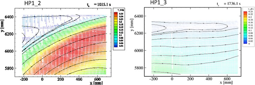
D. Paladino et al. Nuclear Engineering and Design 404 (2023) 112173
Table 1 most of the ERCOSAM-SAMARA experiments were defined minimizing
PANDA projects. phenomena distortions with respect to the generic containment.
Program Investigations The PANDA experiments for the Swissnuclear ESFP project studied
hydrogen concentration build-up into a spent fuel building under a
1991–1995 Investigation of passive decay heat removal systems for SBWR
EPRI/GE postulated severe accident scenario and the key parameter varied within
1996–1998 European BWR-R&D-Cluster for Innovative Passive Safety Systems the test matrix was the location of gas mixture venting from the spent
EC-4th FWP (i.e. SWR1000-KERENA tests) fuel building (Mignot et al., 2016).
(IPPS Project) and ESBWR (TEPSS Project) The OECD/NEA HYMERES project consisted for phase 1 (Paladino
1998–2002 Passive Containment Cooling System (PCCS) performance in very
OECD ISP-42 challenging situations, represented in six different phases (ISP-42)
et al., 2014) in experimental studies at the PANDA and MISTRA (CEA,
1999–2004 Effect of hydrogen distribution on passive systems (TEMPEST France) (Abe et al., 2018) facilities and in phase 2 (Paladino et al.,
EC-5th FWP Project) and investigation of BWR natural circulation stability 2022a) of tests only conducted at the PANDA facility. In the experi
(NACUSP Project) ments, the hydrogen distribution was studied for configurations char
2002–2006 Gas mixing and distribution in LWR containments (SETH Project)
acterized by jet impacting a variety of flow obstructions or being
OECD/NEA
2007–2010 Resolving LWR containment key computational issues (SETH-2 affected by the activation of safety components (Paranjape et al., 2017;
OECD/NEA Project) Andreani et al., 2018; Kapulla et al., 2018; Paranjape et al., 2019;
2010–2014 Containment thermal-hydraulics of current and future LWRs for Andreani et al., 2020; Andreani and Paranjape, 2020; Paladino et al.,
EU 7th FWP severe-accident management (ERCOSAM-SAMARA Project) 2022b; Paranjape et al., 2020; Vázquez-Rodríguez et al. 2023a;), sup
2012–2013 Experimental program on Spent Fuel Pool
Swissnuclear
pression pool phenomena (Gallego-Marcos et al. 2018), system tests
2012–2014 PANDA benchmark (CFD4NRS-5) focusing on natural circulation in two-room compartments (Kapulla
OECD/NEA et al., 2018), and the effect of thermal radiation on the evolution of a
2013–2016 To resolve complex safety issues for the analysis and mitigation of containment atmosphere (Kapulla et al., 2022b). PANDA experiments
OECD/NEA a severe accident leading to hydrogen release into a nuclear
have also been used for international benchmarks (Andreani et al., 2008;
containment (HYMERES project)
2017–2021 To extend the experimental database on hydrogen distribution and Kapulla et al., 2014; Andreani et al., 2016; Andreani et al., 2019).
OECD/NEA on issues related to pressure suppression pool; to create an Currently, PANDA is operated within the OECD/NEA PANDA proj
experimental database on the effect of thermal radiation on the ect, and the experimental investigations address four main topics:
containment atmosphere (HYMERES Phase 2 project) extend the database for large scale flows interacting with containment
2021–2025 PANDA experiments addressing complex safety issues for current
internal structures and for thermal radiation; extend the database during
OECD/NEA water reactors and small modular reactors (SMRs) (PANDA
project) the activation of PWR containment spray; system tests for Small
Modular Reactor (SMR); database extension for suppression pool phe
nomena of BWRs (and IRWST of PWR).
stability behavior of BWRs at low power/low pressure was studied in the It should be noted that the PANDA experiments on hydrogen distri
NACUSP Project (EURATOM 5th FWP) (Auban et al., 2004; Paladino bution in the containment involved postulated BDBA in-vessel scenarios
et al., 2008). Three-dimensional phenomena such as mixing/stratifica (i.e. hydrogen released from MCCI was not investigated so far in
tion and basic flow structures (e.g. near wall plumes (Auban et al., 2007, PANDA). The ESFP project (Mignot et al., 2016), which addresses
Paladino et al., 2010b), free plumes (Zboray and Paladino, 2010), hor hydrogen distribution in a spent fuel pool building, is the only PANDA
izontal jets (Paladino et al., 2010a), and a three-gas free plume test project associated with an ex-vessel scenario, specifically with the spent
(Paladino et al., 2010d)) in LWR containment compartments were fuel building. For all the PANDA experiments helium is used as substi
investigated within the OECD/NEA SETH Project (Paladino et al. 2012), tute of hydrogen.
analytical activities performed at PSI with GOTHIC code of the OECD/ Results from specific PANDA series or projects are published by PSI
NEA SETH PANDA experiments were reported by Andreani et al. authors in journal articles and conference proceedings, selected ones are
(2010a); Andreani and Paladino (2010). Stratification break-up under listed in this paper as references. The experimental activities performed
the effect of heat and mass source and activation of safety components within all the mentioned projects motivated a large amount of compu
were studied in the OECD/NEA SETH-2 project (e.g. Andreani et al., tational analyses including international benchmarks, and a collection
2010b; Erkan et al., 2011; Mignot et al., 2011; Kapulla et al., 2011; of selected articles are provided as references: (Bielert et al., 2001;
Kapulla et al., 2012; Andreani et al., 2012). The SETH-2 project included Stempniewicz, 2001; Andreani et al., 2003; Andreani, 2004; Zavisca and
experiments in PANDA and in the MISTRA facility (CEA, Saclay, France) Ghaderi, 2006; Houkema et al., 2008; Royl et al., 2009; Adamsson et al.,
(Studer et al., 2012). 2012; Papini et al., 2014; Abe et al., 2015; Ishay et al., 2015; Guo et al.,
Within the EURATOM-ROSATOM ERCOSAM-SAMARA project 2015; Malet and Laissac, 2015; Boyd, 2016; Fernández-Cosials et al.,
(Malet et al., 2015; Yudina et al., 2015; Paladino et al., 2016), a 2016; Filippov et al., 2016a; Kelm et al., 2016a; Kelm et al., 2016b; Kelm
postulated scenario scaled from a generic PWR containment was et al., 2017; Sarikurt and Hassan, 2017; Malet et al., 2017; Abe et al.,
investigated, which included the effect of SAM devices such as sprays, 2018; Vázquez-Rodríguez et al., 2023b).
coolers and heaters (simulating the heat release by PARs) on the evo
lution of gas species distribution in the containment (air, steam, helium 2. PANDA facility
as simulant for hydrogen).
The methodology (Benteboula et al., 2015) developed to define the 2.1. Facility characteristics
experiments in the ERCOSAM-SAMARA projects considered as reference
scenario a Small Break LOCA in a PWR with initially dry containment. The original design and scaling of the PANDA facility referred to the
The reference scenarios applied to a generic containment determined by 670 MWe Simplified Boling Water Reactor (SBWR) from General Elec
scaling down from a PWR configuration keeping the ratio between the tric (Yadigaroglu and Dreier, 1988). In the next step, PANDA was
generic and the PWR 1300 containment Volume/Power and Volume/ adapted to the 1200 MWe ESBWR (Economic SBWR) (in the current
Surface factors. ESBWR design the power is 1520 MWe). Based on the ESBWR, GE-
The experiments for the ERCOSAM-SAMARA projects were per HITACHI has developed the Small Modular Reactor (SMR) BWRX-300
formed in PANDA (Paladino et al., 2016; Filippov et al., 2016a), TOS (Ingersoll, 2021). Please note, that PANDA experiments addressing
QAN (IRSN, France) (Filippov et al., 2016b), MISTRA (CEA, France) passive safety systems relevant for SMRs are planned within the OECD/
(Dabbene et al., 2015a) and SPOT (‘‘JSC Afrikantov OKB”, Russia) NEA PANDA project, Table 1.
(Kamnev et al., 2015) facilities. The initial and boundary conditions in A 3D rendering of PANDA facility is shown in Fig. 1. In Fig. 2, a
2
D. Paladino et al. Nuclear Engineering and Design 404 (2023) 112173
large pipes in the water and gas space, the Gravity Driven Cooling
System (GDCS) by a vessel and the RPV by a vessel. For the PANDA
experiments which are not related to the SBWR/ESBWR, the DW and
WW vessels are identified as Vessel 1 to Vessel 4 (Fig. 1). For these tests,
the GDCS vessel was used as water source (if needed) and the RPV as
steam source.
PANDA system lines represent the main components and connections
of the SBWR containment (e.g. Main Steam Lines (MSL), Main Vent Lines
(MVL), PCC return lines, PCC Vent Lines, Vacuum Breakers).
Table 2 lists the main PANDA specification and instrumentation. The
maximum operating conditions of PANDA are 10 bar and 200 ◦ C. The
minimum operation pressure in PANDA is 0.2 bar. Various auxiliary
systems are available for preconditioning the PANDA facility and for
controlling the test initial and boundary conditions.
PANDA instrumentation
The sensors are installed in all PANDA vessels, lines and components.
The measurements are collected by various independent but synchro
nized Data Acquisition Systems (DASs). A subset of PANDA total sensors,
e.g. those particularly relevant within a project, are re-calibrated at the
beginning and end of the project.
Measurements of gas molar fraction (steam, air, helium) in PANDA
are performed using two Mass Spectrometers (MS) systems sampling gas
mixtures through capillaries (160 in total) installed in the four PANDA
vessels (Vessels 1 to 4, Fig. 1). The MS systems are equipped with a
dedicated calibration system which is used to recalibrate the MS for each
PANDA test. The capillaries for gas mixture composition measurements
are always located near (about 10 mm) a thermocouple so that it is
possible to derive additional thermal–hydraulic parameters, e.g. steam
partial pressure (using measurements of absolute pressure in the ves
sels), super-heated or saturated conditions and gas mixture densities.
Two of the PANDA vessels are equipped with optical accesses for
flow visualization and, in particular, for 2D and stereo (3D) PIV mea
surements. PIV measurements are performed in the areas of higher in
terest for the computational analyses of the experiments. These typically
include jet exit velocity profiles, regions of interaction of a jet with
plates or grids, regions of interactions of gases with different densities.
Fig. 1. Isometric view of the PANDA vessels and condenser pools (lines and
PIV measurements are also performed in water pools, for example, for
auxiliary systems are not shown).
the experiment to study steam release to the pressure suppression
chamber through a multi-hole sparger. In Fig. 3 we show as an example,
schematic of PANDA versus the ESBWR are presented where identical a PIV image obtained in a PANDA experiment (HP1_6) within the OECD/
colors indicate same compartments. The PANDA height is about 1:1 NEA HYMERES project in which a buoyant vertical jet interact with a
compared with the SBWR and ESBWR, while the containment volume is horizontal plate (circular disk) located 1 m above the jet exit. The image
about 1:25 with respect to the SBWR and 1:40 for ESBWR (Yadigaroglu shows the vortices created around the horizontal plate and also provide
and Dreier, 1988). information about the overall flow structure.
The electrical heater elements installed in the lower part of the
Reactor Pressure Vessel (RPV) provide a maximum power of 1.5 MW. 3. PANDA experimental database for LWR containment analyses
The PANDA heater elements allow (with some margins) a scaling of
about 1:25 and 1:40 with respect to the thermal power of SBWR (670 As we have described in the introduction, several PANDA projects
MWe) and ESBWR (1200 MWe) that would be released due to the decay include various types of investigations combined into a single project, e.
heat, during a postulated LOCA, about one hour after the SCRAM of the g. related to PWR, BWR, basic phenomena, etc.
reactor. The approach defining the PANDA tests was to create and then
The PANDA control system enables programming the electrical expand the experimental database for each category, taking into account
power curve to imitate the decrease of decay heat as an exponential a variety of geometrical conditions, thermal-hydraulics parameters,
curve after the reactor shutdown. PANDA is equipped with four con component designs, scenarios, reactor concepts, etc.
densers located in four pools (Fig. 2). These PANDA condensers repre In this section, we describe the PANDA experimental databases in
sent the three Passive Cooling Condensers (PCCs) and the one Isolation terms of main test characteristics and phenomena investigated.
Condenser (IC) of the SBWR/ESBWR. The PANDA Passive Cooling PANDA tests fall in either one of the two categories:
Condensers (PCCs) with the related water pools and the pressure sup
pression pool are designed to remove the heat released in the PANDA • tests related to Passive Containment Cooling Systems (PCCS)
RPV, as foreseen for the SBWR/ESBWR. • tests related to basic containment phenomena
Six cylindrical pressure vessels represent in PANDA the containment
volumes and the reactor pressure vessel of the SBWR/ESBWR design.
The SBWR Drywell is represented by two interconnected PANDA vessels,
the Wetwell or suppression pool by two vessels interconnected by two
3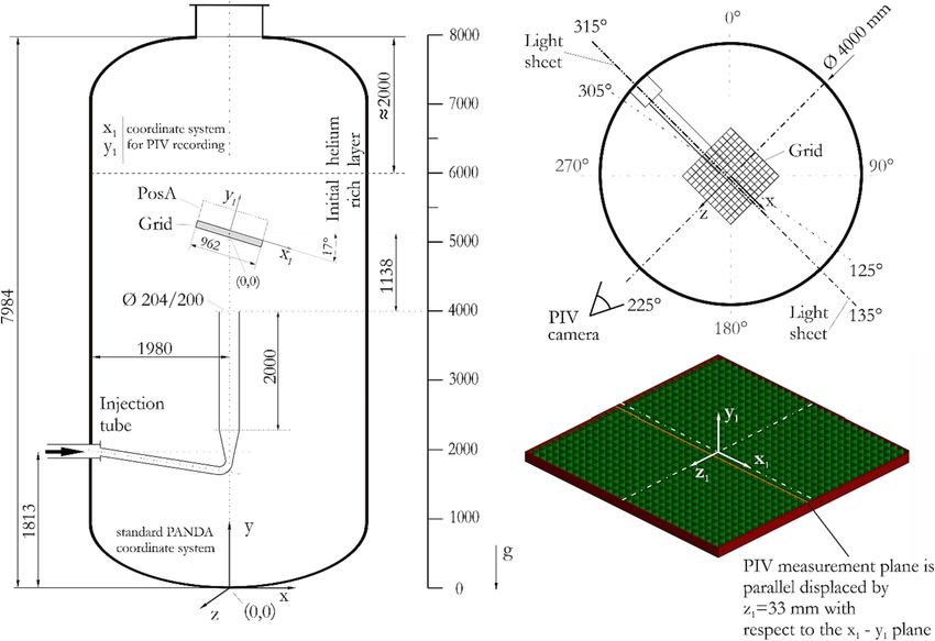
D. Paladino et al. Nuclear Engineering and Design 404 (2023) 112173
Fig. 2. The PANDA facility design (right) is based on the EBWR design (left) (Identical colors indicate volumes or components with identical functions).
Table 2
Overview of PANDA specifications and instrumentation.
Specifications
Electrical power in the RPV (MW) 1.5
Vessels and lines pressure (bar) 0.2–10
Vessels and lines temperature (oC) 200
Total volume of the six Vessels (Fig. 1) (m3) 515
Total volume of the four condenser pools (Fig. 1) (m3) 60
Total height (m) 25
Instrumentation connected to the DAS and CS
No
Thermocouples (vessels, pool, lines) and Pt100 1000
Differential pressure sensors 80
Flow meters 20
Capillaries for gas sampling (connected to MS) 160
Other components
On/OFF and control valves 130
Pumps
Optical accesses for flow visualization in Vessel 1 6
Optical accesses for flow visualization in Vessel 3 3
Control system
Hierarchical PLC system/ Man Machine Interface
Software: Open source EPICS
Note: the number of sensors (No) refer to the sensors connected to the DAS and CS.
The actual number of sensors relevant for each PANDA experiment depends on the
facility configuration, and typically is a subset of the available instrumentation
3.1. PANDA tests related to Passive containment Cooling systems Fig. 3. Mean velocity field in the vicinity above the circular disk for a steam
mass flow rate of 60 g/s which corresponds to experiment HP1_6
The PANDA facility was designed and built to investigate passive (HYMERES project).
systems of advanced LWRs, particularly the SBWR and the ESBWR. One
of the main motivations to build the facility was that licensing of such Standard Problem), which was based on a specific PANDA test consisting
type of reactor required testing of the entire passive systems on a large of six main phases related to PCCS performance in very challenging
scale, e.g. the Passive Containment Cooling Systems. Therefore, the situations (Lübbesmeyer and Aksan, 2003a; 2003b). This benchmark
early tests were performed to meet licensing requirements for the (ISP-42) is the only one that considers the integral passive safety fea
reactor design. tures, and, in some phases, the coupling between primary circuit and the
The increasing interest to better understand the performance of containment. The PANDA test data were extensively used for validation
passive systems (and also the instabilities that could occur in the reactor of LP and system codes (Stempniewicz, 2001; Adamsson et al., 2012;
pressure vessel during start-up conditions) under a variety of scenarios Zavisca and Ghaderi, 2006) but exploratory analyses codes such as
motivated activities such as the European projects IPPS, TEPSS, GOTHIC (suitable for 3D analyses) and CFX (commercial CFD code)
TEMPEST, NACUSP (Table 1) and also the OECD/ISP-42 (International were also performed (Andreani et al., 2003; Andreani, 2004).
4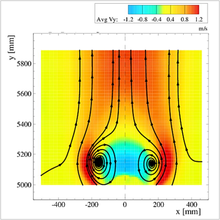
D. Paladino et al. Nuclear Engineering and Design 404 (2023) 112173
All these early PANDA projects address integral behavior of new • Phase 1 (0–10000 s), steam was released from the RPV according to
BWR designs with Passive Safety Systems or have a certain focus, e.g. to the exponentially decreasing decay heat curve, starting one hour
characterize the PCCs and the IC, to study flashing induced instability in after the scram.
the RPV, etc. If we speak of integral behavior, it is meant that the • Phase 2 (10000–17200 s), helium simulating hydrogen was released
transients include the inter-play of all the containment compartments together with steam at the location of the main steam line.
(Drywell, Wetwell, GDCS, PCCs) and features (main vent lines, PCC vent • Phase 3 (17200–42000 s), only steam was released according to the
lines, vacuum breakers, DGRS) and some coupling with the RPV. These decay heat curve.
types of tests, and in particular those for the ISP-42, were mostly
analyzed with classical thermal-hydraulics system codes (e.g. RELAP, In Test T1.3 two PCC unites were connected to Drywell 2 and
TRACE, CATHARE, TRACG, etc.). An overview of the PANDA experi therefore Drywell 1 acted as “dead-volume” as it is shown in Fig. 4.
mental investigations related to passive safety system can be found in The pressure history during the test is shown in Fig. 5. During phase
the article by (Paladino and Dreier, 2012b). Within the ongoing OECD/ 1, the pressure (almost identical in RPV and Drywell) is nearly constant,
NEA PANDA project (Table 1), experiments investigating PCCS in rela which indicates a balance between the energy released in the RPV
tion to BWR SMRs are foreseen. (simulating the decay heat transferred to the steam) and the various
As an example of investigations related to PCCS in PANDA, we show energy sinks by steam condensation (PCCs, wetwell pool, structures). It
a schematic for the PANDA test T1.3 performed within the EURATOM should be noted, that the Drywell 1 and the Wetwell 1 are connected
TEMPEST project (Table 1) in Fig. 4. through the Main Vent line 1 and the Vacuum Breaker line 1 (VB1), and
Test T1.3 was an integral experiment simulating the PCCS behavior the PCC2/PCC3 and Wetwell 2 are connected through the PCC2/PCC3
for a BDBA scenario in which the release of hydrogen in the containment vent lines, Fig. 4. The submergence of the PCC2/PCC3 vent lines in the
was postulated. The test T1.3 consisted of three phases: Wetwell is lower with respect to the Main Vent line 1 submergence.
During the Test T1.3 the venting through the PCC2/PCC3 lines was
constant. The respective values for the Main Vent line 1 at the beginning
Fig. 4. Configuration for the EURATOM TEMPEST PANDA T1.3 experiment.
5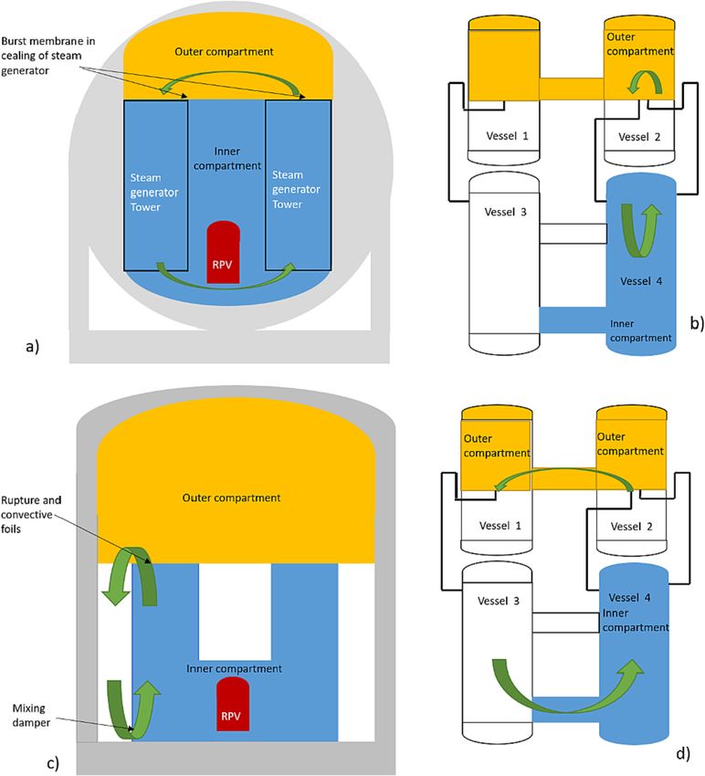
D. Paladino et al. Nuclear Engineering and Design 404 (2023) 112173
Fig. 5. Test T1.3: RPV (MP.RP.1), Drywell (MP.D1) and Wetwell (MP.S1) pressures.
of phase 1 and phase 2 are shown in Fig. 6. Wetwell gas space in phase 3, the pressure becomes nearly constant,
The pressure difference between RPV-Drywell and the Wetwell cor again indicating a balance between the energy released in the RPV
responds to the difference in hydrostatic pressure at the level of the Main (simulating the decay heat transferred to the steam) and the energy
Vent line exit, i.e. the submergence of the vent line in the Wetwell water removed from the PCCs by steam condensation.
pool. In phase 2, the pressure increases due to helium injection. The In Fig. 7, we show the PCC pool level in two pools, e.g. PCC2 and PCC
pressure increase at the beginning of phase 3 is due to the fact that there 3. In the Test T1.3, the initial pool level was about 4.4 m in PCC2 and
is still some amount of helium in the drywell at the end of Phase 2, and, PCC3 and during the experiment no water was added to the pool.
therefore, the helium-steam flow from the Drywell to the Wetwell Therefore, the decrease in water level corresponds to the evaporation in
through the PCC vent line continues. When all the helium is in the the pool due to the steam condensation inside the PCC tubes. It should be
Fig. 6. Test T1.3: Main Vent Line 1 phase indicator (1: indicates venting; 0: indicates not venting).
6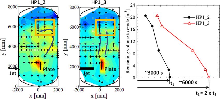
D. Paladino et al. Nuclear Engineering and Design 404 (2023) 112173
Fig. 7. Test T1.3: PCC water level.
noted, that the water level decreases nearly linearly in phase 1 and phase In addition, the different containment concepts require specific
2, however, the slope decreases in phase 2. In fact, during helium in modeling features. For example, there are a variety of safety systems
jection, the overall containment pressurizes and energy is transferred to (spray, coolers, PAR, rupture disks, etc.) whose performance during
various structures (e.g. Drywell wall, Wetwell wall, MV lines) to heat transient operation varies depending on the local thermal-hydraulics
them up according to the saturation temperature which increases during conditions in the vicinity of the systems (e.g. gas mixture composition,
the pressurization (Paladino et al., 2011). Also, the helium has an effect presence of non-condensable, etc.).
on the heat transfer rate. During phase 3, the pool level decreases with Experience in various blind benchmarks (Andreani et al., 2008;
two different slopes. At the beginning of phase 3, the helium flow Andreani et al., 2016; Andreani et al., 2019) has shown that a CFD tool
through the PCC tubes has an effect on the heat transfer rate between the used by different users even with a very similar modeling approach (so
steam-helium mixture and tube wall, later, after about 20000 s, when all called “common model (CM)” may result in quite different outcomes.
the helium is transferred to the Wetwell gas space, the PCC pool slope The specifications provided to the benchmark participants for the CM
rate increases again, due to the fact that the system pressure is constant included the geometry of the PANDA vessel, pipe and flow obstruction,
and there is not energy transferred to the containment structures. treatment of heat transfer at the walls, initial and boundary conditions,
and use the standard high-Reynolds number k-ε turbulence model. A
3.2. PANDA tests related to basic containment phenomena detailed description of the CM specifications can be found in (Andreani
et al., 2019) User experience and judgment in modeling appear to be
3.2.1. Needs of experimental data for containment safety analyses important when using CFD tools.
The need to use computational tools with 3D capabilities for The evolution of containment thermal-hydraulics phenomena during
containment safety analyses was identified since several years (Yadi a transient may be influenced by particular details whose significance
garoglu et al., 2003). A refined 3D model of a containment remains cannot be predicted or recognized a-priori. An example of this are two
computationally challenging, but with the continuous improvement in tests carried out in the framework of OECD/NEA HYMERES: the results
computational power, the advances in knowledge of physical phenom of these two tests (HP1_2 and HP1_3) are shown in Fig. 8. In these tests, a
ena in the containment during postulated accidents and the progress in mixture of helium (to simulate hydrogen) and steam was generated in
numerical techniques, containment safety analyses are accessible the top two meters of vessel 1 (i.e. from 6 m to 8 m), while the remaining
through the use of advanced LP and CFD codes (Broxtermann and part of the vessel was filled with steam. During the experiment, a hori
Allelein, 2013; Kelm et al., 2014; Sonnenkalb et al., 2015; Boyd, 2016; zontal steam jet was injected at a height of about 2 m and first impinged
Papini et al., 2017; Papini et al., 2019). onto a vertical plate (flow obstruction) located some distance in front of
Using CFD tools to predict containment analyses is challenging due the jet outlet, and then eroded the helium-steam layer after changing the
to the phenomenological complexity, which includes, for example, jets, trajectory due to the impact. The helium erosion process is highly
buoyant plumes, wall condensation in the presence of non-condensable dependent on the flow pattern that results after interacting with the flow
gases, re-evaporation phenomena, multi-component gas stratification, obstacle. By only varying the distance between the jet outlet and the
radiative heat transfer, direct condensation in pools, and so on. plate in the HP1_2 test (plate at 209 cm from the jet exit) and HP1_3 test
7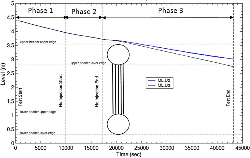
D. Paladino et al. Nuclear Engineering and Design 404 (2023) 112173
Fig. 8. Temperature maps at selected times in the PANDA vessel (left) and erosion time (right) for the HP1_2 and HP1_3 tests. The PIV FOV is indicated in yellow.
(plate at 0.8 m from the jet exit), the time for the erosion of the helium- • geometric configurations,
rich layer changed by a factor 2 (Paranjape et al., 2017). The FOV for the • scenarios,
PIV measurements is shown in yellow in Fig. 8, i.e. the region where the • initial and boundary conditions,
2D flow velocity recorded with PIV, as shown in Fig. 9. • complexity of the phenomena.
It should be pointed out that the PIV FOV, shown in Fig. 9 was in the
central plane of the vessel. For the case of the HP1_2 test the flow ve 4. Large-scale separate effect tests addressing basic containment
locities are higher and more bended, whereas in the case of test HP1_3 phenomena (generic tests):
the velocities are lower and in the region of helium-steam interface are
flattened (to facilitate the visualization streamlines are added in Fig. 9 • Tests in which jets/plumes are released into the containment atmo
showing the main flow direction of the jet after impinging the obstacle, sphere (e.g., air, steam, helium) which cause various phenomena,
in the region of the helium stratification). including stratification or mixing of the atmosphere. These types of
The flow patterns created during these tests were not captured in the tests are defined with different levels of complexity depending on
scoping analyses which were made to define these tests and the timing various considerations (e.g., experience/maturity for analyzing the
for eroding the helium-steam layer were completely unpredicted. The tests with different CFD codes, type of computational tools provided
experimental results and analyses for these tests are described in (Par for the analyses, etc.). For example, phenomena such as condensa
anjape et al., 2017). tion, re-evaporation, thermal radiation, etc. can take place or can be
prevented during the transient process by appropriately defining the
Features of PANDA experiments initial and boundary conditions of the test. Configurations addressed
include (in brackets we provide the project name as indicated in
The PANDA experiments conducted as part of the completed projects Table 1), e.g.:
are designed to create an experimental database suitable for LWR o free or wall jets without stratified helium layer (SETH)
containment analyses. These experiments fall into a list of four major o free or wall plumes with initially stratified helium layer (SETH-2)
categories. Within each category, the experiments address the effects of o horizontal jets impinging onto a vertical concave wall without
a variety of parameters on the evolution of the phenomena. The most stratified helium layer (SETH)
commonly varied parameters are:
Fig. 9. PIV image at given time, showing the average flow velocity at selected times in a given zone in the vessel (shown in Fig. 5 with lines) in the region of the
initial helium-steam layer.
8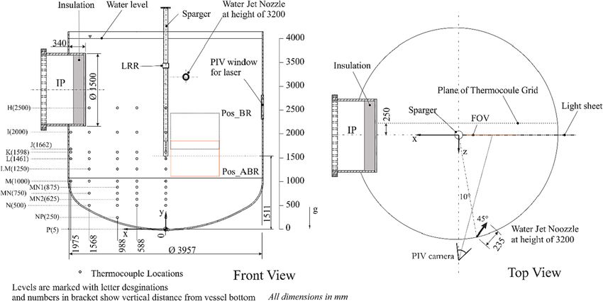
D. Paladino et al. Nuclear Engineering and Design 404 (2023) 112173
o horizontal jets impinging onto a vertical flow obstructions with o A ring with multiple spray nozzles (full cone type) (HYMERES-2)
initially stratified helium layer (HYMERES) o Containment coolers (various designs and various positions in the
o vertical jets impinging onto horizontal flow obstructions with containment) (SETH-2; ERCOSAM; HYMERES-2)
initially stratified helium layer (HYMERES; HYMERES-2) o Array of coolers in the upper dome region (HYMERES-2)
o vertical jet impinging inclined flow obstructions with initially o Combined effects of cooler and spray (HYMERES)
stratified helium layer (HYMERES-2) o PAR heat source (one heat source simulator, two different designs)
• Tests defined to quantify the effect of radiative heat transfer in a (SETH-2, ERCOSAM, HYMERES)
containment atmosphere containing steam, air and helium o PAR heat sources (two heat source simulators) (HYMERES)
(HYMERES-2).
An example of PANDA experiments (HP2/HP3 series of the
As an example, for the PANDA configuration within this category, we HYMERES project) addressing containment safety component is shown
show a schematic of the PANDA Vessel 1 for the OECD/NEA HYMERES- in this paper.
2 experiment H2P1_10_2 in Fig. 10. This experiment consisted of a
vertical jet (with exit at 4 m elevation) impacting onto an inclined grid 6. Complex natural circulation in two-room type containments
(with its center at 1.138 m above the jet exit). The resulting flow after (PWRs):
the grid eroded a helium-steam atmosphere which was initially created
in the upper 2 m of the Vessel. • Tests addressing complex natural circulation in two-room type
The main measurements in vessel 1 during the experiment containment leading to containment atmosphere mixing. These tests
H2P1_10_2 were temperature, gas mixture composition and flow ve addressed two type of designs (e.g. KONVOI and EPRTM type),
locities. A mean velocity field above the grid at tc = 1281 s after the resulting in:
beginning of the test is shown in Fig. 11. The grid breaks the flow in o natural circulation between two steam generator compartments
smaller jets which then merge again in a jet flow about 0.1–0.15 m (after the opening of rupture disks) (HYMERES)
above the grid. The PANDA H2P1_10_2 experiment was used in the o Global natural circulation between the inner room and the
HYMERES-2 project for a blind/open code benchmark (Andreani et al., containment periphery (after opening of rupture disks and mixing
2019). dampers) (HYMERES)
5. Containment safety components (PWRs): 7. Pressure suppression pool phenomena (BWRs):
• Tests dealing with the effects of the activation of safety components • Tests of thermocline formation, evolution and stability in a pressure
(or systems) on the development of containment gas species (air, suppression pool under a variety of configurations and scenarios
steam, helium) distribution. Various test scenarios are used to define including containment pressurization/depressurization, e.g.:
the tests. The considered safety components (or systems) are: o Steam released in the water pool from a multi-hole sparger
o Single spray nozzle (full cone or hollow cone type) (SETH-2; (HYMERES; HYMERES-2)
ERCOSAM; HYMERES-2)
Fig. 10. Coordinate system used for the PIV measurements for experiment H2P1_10_2 (all the dimensions are in mm. The angles (o) are with respect to the PANDA
coordinate system.
9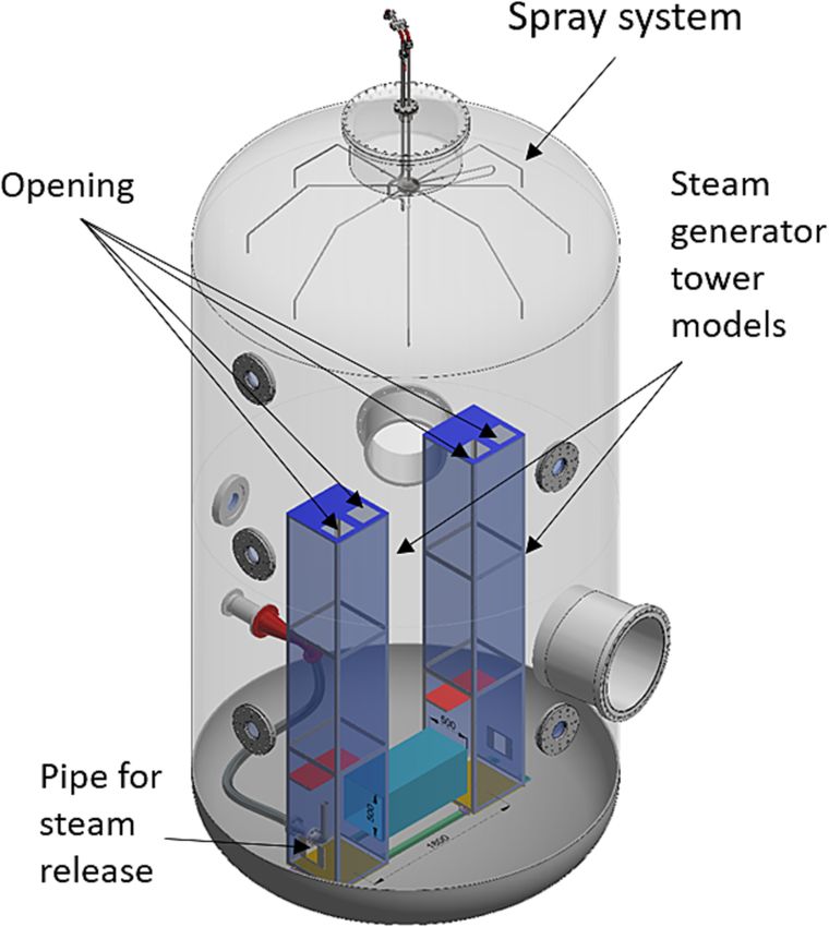
D. Paladino et al. Nuclear Engineering and Design 404 (2023) 112173
Fig. 11. Mean velocity field at tc = 1281 s, for the H2P1_10_2 experiment (shown in the tilted coordinate system).
o Steam and helium released in the water pool from a multi-hole and HP3 series, and complex natural circulation in two-room type
sparger (HYMERES) containments (KONVOI, EPRTM type) in the HP6 series. For example, the
o Steam released in the water pool from a Load Reduction Ring main objective of the HP2/HP3 series was to study the effect of con
(LRR) (HYMERES-2) vection induced by the PAR heat on the distribution of the containment
o Water released in the water pool from a horizontally oriented gas mixture (i.e. helium, steam, air).
nozzle (HYMERES) In a postulated severe accident involving hydrogen release in the
o Combined effect of steam released in the water pool from a multi- containment, the PAR recombines hydrogen with oxygen through
hole sparger and water released in the water pool from a hori exothermic reactions. It should be pointed out that the THAI experi
zontally oriented nozzle (HYMERES) mental facility (Freitag et al., 2022) is operated to investigate the PAR
o Spray activation in the initially pressurized Wetwell and with high behavior under a variety of containment conditions and using proto
temperature gas space above the water pool resulting in de- typical fluids such as hydrogen, steam and air.
pressurization and pool cooling (HYMERES-2) Considering that the PANDA experiments have some important dif
ferences from real PARs (e.g. electric heating instead of a real
8. On the methodologies to define PANDA tests recombiner, use of helium to simulate hydrogen and, therefore, there
was not combustion during the experiments, stainless steel vessel walls
The PANDA facility was originally developed and scaled with respect instead of a concrete walls), scoping analyses were performed to eval
to specific reactor concepts, namely the SBWR/ESBWR and – while uate the phenomena expected in the PANDA experiments compared to
continuously improved over the years – has been used for studies related those envisioned in a generic containment with concrete walls and
to a variety of reactors, e.g. SWR1000 (KERENA), KONVOI/EPRT.M, prototypical PARs.
generic BWRs/PWRs. The original PANDA scaling aimed to the repre The scoping analyses performed for the two series using the GOTHIC
sent all SBWR/ESBWR containment compartments (namely RPV, DW, code generally consisted of several steps (Andreani et al., 2018):
WW, GDCS, IC, PCCs). However, the PANDA studies on other reactor
types usually focus on the effects of activating specific components (e.g. • Collecting and reviewing papers related to real containment pub
spray systems, coolers, PAR heat sources, BWR sparger, PWR rapture lished in the open literature;
disks or mixing dampers) on the phenomena studied in the containment • Identifying key thermal–hydraulic parameters that drive the sce
or specifically in the pressure suppression pool. narios (e.g. pressure history, variation of containment atmosphere
The fact that PANDA has a modular design with multiple vessels and composition, wall condensation rate, etc.);
pool/condensers is an advantage as it provides more flexibility for • Building the model of a real generic PWR containment or compart
different configurations. Nevertheless, each type (or category) of ment and reproduce the identified parameters as published in the
PANDA experiments requires some modifications to the facility (e.g. literature;
piping, partitions, auxiliary systems, etc.) and implementation of com • Then, a large number of simulations are performed with a variety of
ponents (e.g. coolers, spray, heat sources, etc.) and instrumentation. affordable upgrading (e.g. lines, components, partitions, etc.), to
Defining PANDA tests in terms of specific reactors (which were not reproduce in PANDA the effect of features such as PAR, vacuum
originally considered for the PANDA scaling) requires a multi-step breakers, mixing dampers, steam generator compartments or phe
approach for the scoping analyses. Some examples of test definitions nomena such as condensation on the concrete walls, natural circu
for PWRs and BWR are provided below. lation, PAR recombination rate, etc. on the containment phenomena.
Based on these multilevel scoping analyses, the modifications to the
8.1. PANDA tests related to PWRs PANDA facility are identified that allow the postulated scenarios to
predict the phenomena in the real plant containment with acceptable
Examples of the application of the multistage methodology include deviations.
the OECD/NEA HYMERES project PANDA tests (Table 1) to study the The outcome of such evaluation process are shown as a 3D PANDA
thermal effect of Passive Autocatalytic Recombiners (PAR) in the HP2
10D. Paladino et al. Nuclear Engineering and Design 404 (2023) 112173
rendering for the configuration to study the effect of PAR heat source on 3 and 4) and experimental conditions are published in (Andreani et al.,
the distribution of gas species in the containment atmosphere (HP2/HP3 2018), while the PANDA experimental results are published in (Kapulla
series) in Fig. 12. The detailed experimental results and the computa et al., 2018).
tional analyses of these tests are published in the articles (Paranjape
et al., 2020; Andreani and Paranjape, 2020). The activation time and the 8.2. PANDA tests related to BWRs
heating power curve were defined with the scoping analyses to resemble
a postulated accident scenario. In addition, the scoping analyses allowed The methodology to define these PANDA tests for the HP5 series of
the design of vertical condensers (cooling tubes) in the PANDA vessel to the OECD HYMERES project and the experimental results of the whole
represent condensation on the wall of a concrete containment to in series including comparisons with the PPOOLEX experiments performed
crease the similarity to phenomena in a real generic PWR containment. at LUT (Finland) are described in the article by (Gallego-Marcos et al.,
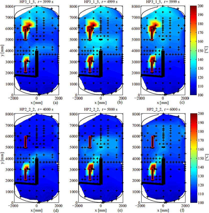
Temperature maps in the vessel obtained at specific times during two 2018), and the computational analyses of some tests in the article by
tests addressing the activation of the PAR heater simulators are shown in (Gallego-Marcos et al., 2019).
Fig. 13. One of the main goals of the tests was to generate an experimental
Another example of the outlined approach is the HP6 series. The database suitable for the pool modeling and analyses with CFD tools.
objective of the HP6 series was to investigate, the effect of natural cir The phenomena that took place in the pool during the tests include:
culation on the hydrogen distribution in two-room type containment in condensation of vapor in direct contact with the water, convection,
the case of a postulated accident. formation and stability of a thermocline, etc.
The representation in PANDA of the KONVOI type (with a circuit of The reference BWR design and the postulated accident scenarios
natural circulation between two steam generator towers and the dome) were the BWR Mark II design and the Station Black Out (SBO) scenarios
and of the EPRTM type (with a global circuit of natural circulation be for these tests. In addition, spargers typical of Mark II and Mark III were
tween the inner compartment and the annulus/dome) used 4 vessels and considered for scaling the experiments. The sparger was characterized
additional piping and partitions as shown in Fig. 14. by a vertical pipe with multi-holes for the steam release located in the
In normal operation, the two compartments are separated and the sparger head and in the so called load reduction ring (a detailed
outer compartment is accessible to the plant personnel. In the event of a description of the sparger geometry can be found in the article by
postulated accident, bursting membranes (in the case of KONVOI (Gallego-Marcos et al., 2018).
containment) and rupture and convective foils plus mixing dampers (in The scaling used to define the experimental parameters included the
the case of EPRTM) open (break) passively as soon as small temperature macro (water pool), meso (sparger pipe) and micro scale (sparger injec
and pressure differences (due to the steam release) occur between the tion holes of the sparger), so that phenomena in the experiments would
two spaces and the natural circulation loops contribute to the mixing of occur with acceptable deviations from those expected in the postulated
the containment atmosphere. accident in the plant. A schematic of the PANDA vessel with the lines
The detailed scoping analyses using GOTHIC to define PANDA showing the locations of thermocouples is shown in Fig. 15. The vertical
modifications (e.g. choice of lines between lower and upper vessels, tube in the center represents the sparger. Note that the dotted red square
subdivision of the lower vessels by closing the upper interconnecting near the sparger head represents the typical areas of investigation for
pipe, and damper in the lower interconnecting pipe between the vessels PIV in this type of experiments.
Fig. 16 and Fig. 17 refer to the PANDA HP5_4 test of the HYMERES
project. In the HP5_4 test, the initial water pool level and temperature
were 4 m and 55–60 ◦ C, respectively. The sparger was installed 1.5 m
above the bottom of the vessel, as shown in the front view in Fig. 15.
The HP5_4 test consisted of two main phases: Phase 1 from 0 to 6000
s and phase 2 from 6000 to 9000 s. In both phases, steam was injected
through the sparger into the pool at a constant flow rate of 160 g/s. In
phase 2, water was additionally injected through a nozzle located inside
the pool at a height of 3.2 m above the bottom of the vessel (see Fig. 15,
top view). The water flow rate and temperature were 2 kg/s and 25 ◦ C,
respectively.
The evolution of pool temperature at various elevations is shown in
Fig. 16. Injection of steam in phase 1 resulted in the formation of a
thermocline in the pool with temperature differences of about 15 ◦ C
(Fig. 16). Injecting water through the nozzle in phase 2 resulted in the
progressive homogenization of the pool temperature.
A 2D velocity field for the pool in the region of the sparger exit and a
2D temperature map at 5386 s (near the end of Phase 1) is shown in
Fig. 17. The velocities are in the range of 0 to 0.2 m/s, and the pattern
induced by the sparger is nearly vertical to the bottom of the pool. The
2D temperature map shows that a temperature difference is formed in
the pool and the water below 500 mm is not heated by the steam release
through the sparger.
9. Further experimental needs for containment safety analyses
and for SMRs
In the previous sections, we provided an overview of experimental
studies conducted in PANDA and classified them into specific categories.
We pointed out that the approach so far has been to create and extend
Fig. 12. 3D rendering of PANDA vessel with the main components for the HP2/ the experimental database within the specific categories, with the aim of
HP3 series. covering the phenomena, configurations, safety components, scenarios,
11D. Paladino et al. Nuclear Engineering and Design 404 (2023) 112173
Fig. 13. Temperature patters at selected times in Vessel 1 for experiments HP3_1_5 and HP2_2_2.
etc. needed for containment safety analyses. Based on the results from two large compartments representing two steam generator tower models
the OECD/NEA HYMERES-2 project (Paladino et al., 2022a), we have and a spray system in the upper dome is presented in Fig. 18.
identified the following further needs for containment safety analyses to
be addressed within and beyond the ongoing OECD/NEA PANDA project 9.2. Large-scale separate effect tests addressing basic containment
(Table 1). phenomena
9.1. Experiments related to flow obstructions and PWR components The H2P2 series of the OECD/NEA HYMERES-2 project (Kapulla
et al., 2022b) confirmed that radiative heat transfer affects containment
The structures present in the containment (walls, floors, components, atmosphere temperature even for gas mixtures with very low vapor
etc.) would constitute obstacles in the event of a postulated accident content (e.g. about 0.2 % molar fraction). It is necessary to further
involving the release of steam and hydrogen and would influence the investigate the effects of radiative heat transfer by defining experiments
overall distribution of gas mixture. Experiments have been conducted in that address phenomena that are expected to occur in postulated acci
previous projects where plates (horizontal or vertical) or grids (hori dent scenarios.
zontal or inclined) were considered as flow obstacles. The experimental
data base needs to be expanded to include containment flow in presence 9.3. Additional experiments related to suppression pool phenomena and
of realistic compartments, such as steam generator tower models, that system behavior
result in complex natural circulation phenomena that contribute to
mixing of the containment atmosphere. In addition, he experimental The PANDA series HP5 (HYMERES) and H2P3 and H2P4 (HYMERES-
data base needs to be further developed to account for the combined 2) were dedicated to pool phenomena. The HP5 and H2P3 series were
effect of complex flow obstacles and the activation of safety systems such performed keeping the pressure in the gas space above the water pool
as spray rings or cooler arrays. A corresponding experimental setup with constant.
12D. Paladino et al. Nuclear Engineering and Design 404 (2023) 112173
Fig. 14. Conceptual schematic of a two-room type containment with the main flow circulation loop (a) for the “KONVOI-type” and c) “EPR-type” as well as the
respective representation in PANDA b) and d).
It is necessary to expand the experimental database on pool phe database for BWRs (containment and reactor pressure vessel) needs to
nomena under the effect of steam venting from multi-hole sparger, with be further expanded to include configurations where all compartments
sparger designs that have not been tested in the previous experiments or (drywell, wetwell, reactor pressure vessel) and features (vent lines/
blow-down pipes. In this context, it would be also valuable to release a blowdown pipe, spray systems, cooling systems) are represented for a
mixture of steam and non-condensable gases through the sparger. The variety of designs and postulated accident scenarios.
new experiments can be performed considering various pressure his
tories (constant and/or variable containment pressure) and will allow us
to expand the database for characterizing the conditions that lead to the 9.4. Experiments related to SMRs
formation of the thermoclines in the water pool.
The H2P4 series was the first PANDA series to relate the pressure An experimental database OECD/NEA PANDA project (Table 1) on
response in the containment to the pool heat sink capability under two safety relevant phenomena for SMRs is being established as part of the
main conditions: steam release through the sparger in the water pool or OECD/NEA PANDA project (Table 1). The needs identified so far
spraying of water in the gas phase above the pool. The experimental concern experimental data for the study of SMR passive systems such as
PCCS and IC.
13D. Paladino et al. Nuclear Engineering and Design 404 (2023) 112173
Fig. 15. Schematic of the PANDA vessel, sparger head and instrumentation location.
Fig. 16. Temperature history at selected locations in the water pool during the test.
Another set of PANDA experiments related to SMRs will address heat diffusion, stratification erosion; condensation; re-evaporation; thermal
transfer by natural convection from the external wall of an immersed radiation; etc.) and on the safety components (e.g. spray, cooler, PAR
containment to the surrounding water pool. heating model, etc.) that affect hydrogen distribution in the
containment.
10. Conclusions and outlook PANDA experiments related to specific PWRs and BWRs (i.e. heat
source simulating thermal effect of PAR, complex natural circulation in
In this paper, we have provided an overview of the PANDA projects two-room type containment) were defined based on a methodology
and highlighted some of the key features of certain “categories” of in aimed at representing the phenomena in PANDA with acceptable biases
vestigations. The PANDA experiments related to passive safety systems, with respect to the phenomena expected during postulated accident
some of which were used for ESBWR PCCS approval, created an integral scenarios in the real reactor containment.
behavior database and were used to benchmark a number of computa PANDA experiments related to pressure suppression pools in BWRs
tional tools within ISP-42. have created an experimental database on the formation and evolution
PANDA experiments related to the hydrogen risk created an exper of thermocline in water pool under the influence of steam release from
imental database of relevant phenomena (e.g. gas distribution, mixing, the multi-hole sparger under a variety of conditions. In addition, some of
14D. Paladino et al. Nuclear Engineering and Design 404 (2023) 112173
Fig. 17. Velocity (POS_ABR in Fig. 16) and temperature maps at 5386 s for experiment HP5_4 (not to scale).
phenomena; experiments on suppression pool phenomena and system
behavior. The OECD/NEA PANDA project addresses the identified needs
and phenomena relevant for the safety of SMRs.
Declaration of Competing Interest
The authors declare that they have no known competing financial
interests or personal relationships that could have appeared to influence
the work reported in this paper.
Data availability
Data will be made available on request.
Acknowledgements
We would like to dedicate this article to Max Fehlmann (25. May
1960; † 30.11.2021) for his engaged contribution to the PANDA projects.
Most of the PANDA projects were conducted with the technical and
financial support of countries within the OECD/NEA framework. Other
PANDA projects through the EURATOM frameworks. The support of
OECD/NEA and of EURATOM are gratefully acknowledged.
References
Abe, S., Ishigaki, M., Sibamoto, Y., Yonomoto, T., 2015. RANS analyses on erosion
behavior of density stratification consisted of helium–air mixture gas by a low
Fig. 18. Rendering of PANDA Vessel 1 with two large compartments. momentum vertical buoyant jet in the PANDA test facility - The third international
benchmark exercise (IBE-3). Nuclear Engineering and Design 289, 231–239. https://
doi.org/10.1016/j.nucengdes.2015.04.002.
the experiments allowed to quantify the pressure evolution in the Abe, S., Studer, E., Ishigaki, M., Sibamoto, Y., Yonomoto, T., 2018. Stratification breakup
containment in relation to the reduction of the pool’s heat sink by a diffuse buoyant jet: The MISTRA HM1-1 and HP1-1bis experiments and their
CFD analysis. Nuclear Engineering and Design 331, 162–175. https://doi.org/
capability.
10.1016/j.nucengdes.2018.01.050.
Based on the results of the OECD/NEA HYMERES-2 project, we have Adamsson, C., Papini, D., Zerkak, O., Prasser, H.-M., 2012. 2012, Simulation Of
identified in this paper the further need for experiments on containment International Standard Problem ISP-42. Phases A And B With The Trace Code,
safety analyses in three main areas: Experiments on flow obstacles and NUTHOS.
Andreani, M., 2004. Pre-Test Calculations of Phase A of the ISP-42 (PANDA) using the
PWR components; large-scale separate effects tests on basic containment GOTHIC Containment Code and Comparison with the Experimental Results. Nuclear
Technology 148, 35–47.
15D. Paladino et al. Nuclear Engineering and Design 404 (2023) 112173
Andreani, M., Badillo, A., Kapulla, R., 2016. Synthesis of the OECD/NEA-PSI CFD Fernández-Cosials, M.-K., Jimenez, G., López-Alonso, E., 2016. Analysis of a Gas
benchmark exercise. Nuclear Engineering and Design 299, 59–80. https://doi.org/ Stratification Break-up by a Vertical Jet using the GOTHIC Code. Nuclear
10.1016/j.nucengdes.2015.12.029. Engineering and Design 297, 123–135. https://doi.org/10.1016/j.
Andreani, M., Kapulla, R., and Zboray, R., 2010b, Simulation of Break-up of Gas nucengdes.2015.11.035.
Stratification by a Vertical Jet using the GOTHIC Code, In Proc: 8th International Filippov, A., Grigoryev, S., Drobyshevsky, N., Kiselev, A., Shyukin, A., Yudina, T., 2016a.
Topical Meeting on Nuclear Thermal-Hydraulics, Operation and Safety (NUTHOS-8), CMFD simulation of ERCOSAM PANDA spray tests PE1 and PE2. Nuclear
Shanghai, China, October 10-14. Engineering and Design 299, 81–94. https://doi.org/10.1016/j.
Andreani, M., Kapulla, R., Zboray, R., 2012. Gas stratification break-up by a vertical jet: nucengdes.2015.10.013.
simulations using the GOTHIC code. Nuclear Engineering and Design 249, 71–81. Filippov, A.S., Grigoryev, S.Y., Tarasov, O., 2016b. 2016, ‘On the possible role of thermal
https://doi.org/10.1016/j.nucengdes.2011.06.004. radiation in containment thermal experiments by the example of CFD analyses of
Andreani, M., Paladino, D., 2010. Simulation of gas mixing and transport in a multi- TOSQAN T114 air-He test’. Nuclear Engineering and Design 310, 175–186.
compartment geometry using the GOTHIC containment code and relatively coarse Freitag, M., Schmidt, E.W., Sonnenkalb, M., Kelm, S., Kotouč, M., Liange, Z., Royl, P.,
mesh. Nuclear Engineering and Design 240, 1506–1527. https://doi.org/10.1016/j. Benz, S., December 2022. CFD and LP code benchmark evaluating the onset of par
nucengdes.2010.02.020. operation in case of extremely low oxygen concentration. Nuclear Engineering and
Andreani, M., Putz, F., Dury, T.V., Gjerloev, C., Smith, B.L., 2003. On the Application of Design 400 (15), 112056.
Field Codes to the Analysis of Gas Mixing in Large Volumes: Case studies using CFX Gallego-Marcos, I., Kudinov, P., Villanueva, W., Kapulla, R., Paranjape, S., Paladino, D.,
and GOTHIC. Annals of Nuclear Energy 30, 685–714. https://doi.org/10.1016/ Laine, J., Puustinen, M., Räsänen, A., Pyy, L., Kotro, E., 2018. Pool Stratification and
S0306-4549(02)00113-5. Mixing Induced by Steam Injection through Spargers: analysis of the PPOOLEX and
Andreani, M., Haller, K., Heitsch, M., Hemström, B., Karppinen, I., Macek, J., Schmid, J., PANDA experiments. Nuclear Engineering and Design 337, 300–316. https://doi.
Pailler, H., Toth, I., 2008. A benchmark exercise on the use of CFD codes for org/10.1016/j.nucengdes.2018.07.004.
containment issues using best practice guidelines: A computational challenge. Gallego-Marcos, I., Kudinov, P., Villanueva, W., Kapulla, R., Paranjape, S., Paladino, D.,
Nuclear Engineering and Design 238 (3), 502–513. https://doi.org/10.1016/j. Laine, J., Puustinen, M., Räsänen, A., Pyy, L., Kotro, E., 2019. Pool stratification and
nucengdes.2007.01.021. mixing induced by steam injection through spargers: CFD modelling of the PPOOLEX
Andreani, M., Paladino, D., George, T., 2010a. Simulation of basic gas mixing tests with and PANDA experiments. Nuclear Engineering and Design 347 (2019), 67–85.
condensation in the PANDA facility using the GOTHIC code. Nuclear Engineering https://doi.org/10.1016/j.nucengdes.2019.03.011.
and Design 240, 1528–1547. https://doi.org/10.1016/j.nucengdes.2010.02.021. Gamble, R.E., Nguyen, T.T., Shiralkar, B.S., Peterson, P.F., Greif, R., Tabata, H., 2001.
Andreani, M., Paladino, D., Papini, D., 2018. Multi-Step Planning Calculations with the Pressure suppression pool mixing in passive advanced BWR plants. Nuclear
GOTHIC Code Used for the Design of Complex Experiments in the PANDA Facility. Engineering and Design 204 (1–3), 321–336. https://doi.org/10.1016/S0029-5493
Nuclear Engineering and Design 339, 116–125. https://doi.org/10.1016/j. (00)00363-0.
nucengdes.2018.09.005. Guo, S., Cai, J., Zhang, H., Yin, H., Yang, X., 2015. Study of the distribution of steam
Andreani, M., Gaikwad, A.J., Ganju, S., Gera, B., Grigoryev, S., Herranz, L.E., plumes in the PANDA facility using CFD code. Nuclear Engineering and Design 289,
Huhtanen, R., Kale, V., Kanaev, A., Kapulla, R., Kelm, S., Kim, J., Nishimura, T., 81–91. https://doi.org/10.1016/j.nucengdes.2015.04.016.
Paladino, D., Paranjape, S., Schramm, B., Sharabi, M., Shen, F., Zhang, R., 2019. Houkema, M., Siccama, N., Nijeholt, J.L.Ã., Komen, E., 2008. Validation of the CFX4 CFD
Synthesis of a CFD benchmark exercise based on a test in the PANDA facility code for containment thermal-hydraulics. Nuclear Engineering and Design 238,
addressing the stratification erosion by a vertical jet in presence of a flow 590–599. https://doi.org/10.1016/j.nucengdes.2007.02.033.
obstruction. Nuclear Engineering and Design 354. https://doi.org/10.1016/j. Huggenberger, M., Aubert, C., Bandurski, T., Dreier, J., Fischer, O., Strassberger, H. J.,
nucengdes.2019.110177. Yadigaroglu, G., 1999, ESBWR Related Passive Decay Heat Removal Tests in PANDA.
Andreani, M., Kapulla, R., Kelm, S., Paladino, D., Paranjape, S., 2020. Analyses of Gas In Proc.: International Conference on Nuclear Energy (ICONE-7), Tokyo, Japan.
Stratification Erosion by a Vertical Jet in Presence of an Obstacle Using the GOTHIC Ingersoll, D.T., 2021. 2 - Small modular reactors (SMRs) for producing nuclear energy:
Code. Journal of Nuclear Engineering and Radiation Science 6 (2), 21110. International developments”. Handbook of Small Modular Nuclear Reactors (Second
Andreani, M., Paranjape, S., 2020. Gas mixing caused by interacting heat sources. Part ii: Edition) 29–50.
Modelling. Nuclear Engineering and Design 370, 110887. https://doi.org/10.1016/ Ishay, L., Bieder, U., Ziskind, G., Rashkovan, A., 2015. Turbulent jet erosion of a stably
j.nucengdes.2020.110887. stratified gas layer in a nuclear reactor test containment. Nuclear Engineering and
Auban, O., Paladino, D., Zboray, R., 2004. Experimental investigation of natural- Design 292, 133–148. https://doi.org/10.1016/j.nucengdes.2015.06.001.
circulation flow behaviour under low-power/low-pressure conditions in the large- Kamnev, M., Tyurikov, O., Khizbullin, A., Kiselev, A., Yudina, T., Paladino, D., Andreani,
scale PANDA facility. Nuclear Technology 148, 294–312. M., Overview of SPOT Experimental and Analytical Activities with KUPOL,
Auban, O., Zboray, R., Paladino, D., 2007. Investigation of large-scale gas mixing and International Congress on Advances in Nuclear Power Plants (ICAPP, 2015. May 3–6,
stratification phenomena related to LWR containment studies in the PANDA facility. 2015. Nice, France.
Nuclear Engineering and Design 237, 409–419. https://doi.org/10.1016/j. Kapulla, R., Mignot, G., Paladino, D., Erkan, N., Zboray, R., 2011, Thermal-Hydraulic
nucengdes.2006.07.011. Phenomena Caused by the Interaction of Steam and Steam-Helium Mixture Wall Jets
Bandurski, T., Huggenberger, M., Dreier, J., Aubert, C., Putz, F., Gamble, R.E., with a Containment Cooler, International Congress on Advances in Nuclear Power
Yadigaroglu, G., 2001. Influence of the distribution of noncondensibles on passive Plants (ICAPP 2011), Nice, France, May 2-5.
containment condenser performance in PANDA. Nuclear Engineering and Design Kapulla, R., Mignot, G., Paranjape, S., Ryan, L., Paladino, D., 2014, Large Scale Gas
204 (1–3), 285–298. https://doi.org/10.1016/S0029-5493(00)00317-4. Stratification Erosion by a Vertical Helium-Air Jet”, Science and Technology of
Benteboula, S., Malet, J., Bleyer, A., Bentaib, A., Paladino, D., Guentay, S., Andreani, M., Nuclear Installations journal Volume 2014 (2014), Article ID 197267.
Tkatschenko, I., Brinster, J., Dabbene, F., Kelm, S., Allelein, H. J., Visser, D. C., Benz, Kapulla, R., Paranjape, S., Doll, U., Kirkby, E., Paladino, D., 2022b Experimental
S., Jordan, T., Liang, R., Kiselev, A., Yudina, T., Filippov, A., Khizbullin, A., Kamnev, Assessment of Thermal Radiation Effects on Containment Atmospheres with Varying
M., Zaytsev, A., Loukianov, A., 2015,EUROATOM-ROSATOM-ERCOSAM-SAMARA Steam Content, Nuclear Engineering and Technology, Available online 6 July 2022.
PROJECTS Scaling from Nuclear Power Plant to experiments. International Congress https://doi.org/10.1016/j.net.2022.07.001.
on Advances in Nuclear Power Plants (ICAPP 2015), May 3-6, 2015, Nice, France. Kapulla, R., Mignot, G., Paladino, D., 2012. Large-scale containment cooler performance
Bielert, U., Breitung, W., Kotchourko, A., Royl, P., Scholtyssek, W., Veser, A., experiments under accident conditions. Science and Technology of Nuclear
Beccantini, A., Dabbene, F., Paillere, H., Studer, E., Huld, T., Wilkening, H., Installations 943197, 2012.
Edlinger, B., Poruba, C., Mohaved, M., 2001. Multi-dimensional simulation of Kapulla, R., Mignot, G., Paranjape, S., Paladino, D., 2018. Large Scale Experiments
hydrogen distribution and turbulent combustion in severe accidents. Nuclear Representing a Containment Natural Circulation Loop During an Accident Scenarios.
Engineering and Design 209, 165–172. https://doi.org/10.1016/S0029-5493(01) Science and Technology of Nuclear Installation. https://doi.org/10.1155/2018/
00399-5. 8989070.
Boyd, C., 2016. Perspectives on CFD analysis in nuclear reactor regulation. Nuclear Kelm, S., Klauck, M., Beck, S., Allelein, H.J., Preusser, G., Sangiorgi, M., Klein-
Engineering. and Design 299, 12–17. https://doi.org/10.1016/j. Hessling, W., Bakalov, I., Bleyer, A., Bentaib, A., Kljenak, I., Stempniewicz, M.,
nucengdes.2015.08.001. Kostka, P., Morandi, S., Ada del Corno, B., Bratfisch, C., Risken, T., Denk, L.,
Broxtermann, P., Allelein, H.J., 2013. Simulation of AP1000’s passive containment Parduba, Z., Paci, S., Manfredini, M., Silde, A., Juris, P., Jancovic, J., Lele, H.J.,
cooling with the German Containment Code System COCOSYS. Nuclear Engineering Ganju, S., 2014. Generic Containment: Detailed comparison of containment
and Design 261, 326–332. https://doi.org/10.1016/j.nucengdes.2012.09.038. simulations performed on plant scale. Annals of Nuclear Energy 74 (2014), 165–172.
Dabbene, F.; Brinster, J.; Abdo, D.; Porcheron, E.; Lemaitre, P.; Mignot, G.; Kapulla, R.; https://doi.org/10.1016/j.anucene.2014.07.006.
Paranjape, S.; Kamnev, M., Khizbullin, A., 2015a, Experimental Activities on Kelm, S., Ritterath, M., Prasser, H.-M., Allelein, H.-J., 2016a. Application of the
Stratification and Mixing of a Gas Mixture under the Conditions of a Severe Accident MiniPanda test case “Erosion of a stratified layer by a vertical jet” for CFD validation.
with Intervention of Mitigating Measures Performed in the ERCOSAM-SAMARA Nuclear Engineering and Design 299, 124–135. https://doi.org/10.1016/j.
Projects, ICAPP 2015. nucengdes.2015.08.013.
Dreier, J., Aubert, C., Huggenberger, M., Strassberger, H.J., Meseth, J., Yadigaroglu, G., Kelm, S., Lehmkuhl, J., Jahn, W., Allelein, H.J., 2016b. A comparative assessment of
1999. The PANDA Tests for the SWR1000 Passive Containment Cooling System, In different experiments on buoyancy driven mixing processes by means of CFD. Annals
Proc.: 7th International Conference on Nuclear Engineering (ICONE-7), Tokyo, of Nuclear Energy 93, 50–57. https://doi.org/10.1016/j.anucene.2015.12.032.
Japan, April 19-23. Kelm, S., Kapulla, R., Allelein, H.-J., 2017. Erosion of a confined stratified layer by a
Erkan, N., Kapulla, R., Mignot, G., Zboray, R., Paladino, D., 2011. Experimental vertical jet. Detailed assessment of a CFD approach against the OECD/NEA PSI
investigation of spray induced gas stratification break-up and mixing in two benchmark. Nuclear Engineering an Design 312, 228–238. https://doi.org/10.1016/
interconnected vessels. Nuclear Engineering and Design 241, 3935–3944. https:// j.nucengdes.2016.09.014.
doi.org/10.1016/j.nucengdes.2011.07.025. Lübbesmeyer, D., and Aksan, S.N., 2003a, ISP42 (PANDA TESTS) Blind Phase
Comparison Report, NEA/CSNI/R(2003)6.
16You can also read