Negative potential energy content analysis in cracked rotors whirl response
←
→
Page content transcription
If your browser does not render page correctly, please read the page content below

www.nature.com/scientificreports
OPEN Negative potential energy content
analysis in cracked rotors whirl
response
Mohammad A. AL‑Shudeifat1* & Fatima K. Alhammadi2
Appearance of transverse cracks in rotor systems mainly affects their stiffness content. The stability of
such systems at steady-state running is usually analyzed by using the Floquet’s theory. Accordingly,
the instability zones of rotational speeds are dominated by negative stiffness content in the whirl
response in the vicinity of critical rotational speeds. Consequently, an effective stiffness measure
is introduced here to analyze the effect of the crack and the unbalance force vector orientation
on the intensity of negative potential and stiffness content in the whirl response. The effective
stiffness expression is obtained from the direct integration of the equations of motion of the
considered cracked rotor system. The proposed effective stiffness measure is applied for steady-
state and transient operations using the Jeffcott rotor model with open and breathing crack models.
The intensity of negative potential and stiffness content in the numerical and experimental whirl
responses is found to be critically depending on the propagation level of the crack and the unbalance
force vector orientation. Therefore, this can be proposed as a crack detection tool in cracked rotor
systems that either exhibit recurrent passage through the critical rotational speeds or steady-state
running.
Appearance of transverse cracks in rotor systems significantly affects their whirl response dynamical behavior.
Propagation of transverse cracks could result in destructive whirl vibration amplitudes and rapid failure of rotor
systems. Therefore, early detection of crack damages is critical for human safety and durability of rotor systems
that are extensively applied in heavy-duty industrial applications.
Several types of crack damages have been addressed in the literature. However, two main types of cracks
which are the transverse open and breathing crack models, have been extensively studied up-to-date. Most of the
reported literature for transient and steady-state operations of rotor systems have been focused on the dynamical
behavior of vibration whirl response in the vicinity of critical, subcritical and supercritical rotational speeds. The
whirl dynamical behavior in the vicinity of critical and subcritical rotational speeds was investigated i n1 to dif-
ferentiate between the whirl responses of these crack models in a cracked rotor system at steady-state operations.
It was found that the forward subcritical whirl amplitudes were not observed in open crack model compared
with breathing crack model. Several Vibration-Based Methods (VBMs) have been employed for crack damage
detection. In2–5, the VBMs were used for damage detection in rotor systems through whirl response analysis.
In addition, VBMs have been applied to study the effect of crack damages on stiffness and damping properties
in6,7. Analytical and numerical methods were applied to the equations of motion of a cracked rotor system in8
to study the whirl response dynamical behavior.
In several studies, the transient whirl response during startup operations in which angular acceleration
rate was considered in the equations of motion has been well-studied for cracked rotor systems with open and
breathing crack models i n9–16. In9, experimental investigations have been conducted for analyzing the transient
vibrational whirl behavior during the passage through the critical rotational speed. The transient whirl response
was investigated to distinguish between the effect of the transverse and slant crack models in10,11 and between the
responses of transverse crack and the shaft misalignment in rotor systems in12. Recently, a new backward whirl
phenomena named as a post-resonance backward whirl has been captured in the transient response of accelerated
cracked rotor systems immediately after the passage through the critical forward whirl s peeds13–15. This post-
resonance backward whirl was found to be associated with an abrupt reduction in whirl amplitudes in the vicinity
of local minima of whirl amplitudes. The Hilbert–Huang Transform (HHT) which is a time frequency analysis
method was employed in16,17 to study the transient vibration whirl response of rotors with transverse cracks.
1
Khalifa University of Science & Technology, PO BOX 127788, Abu Dhabi, United Arab Emirates. 2Tawazun
Technology & Innovation, PO BOX 908, Abu Dhabi, United Arab Emirates. *email: mohd.shudeifat@ku.ac.ae
Scientific Reports | (2021) 11:15294 | https://doi.org/10.1038/s41598-021-94836-8 1
Vol.:(0123456789)
www.nature.com/scientificreports/
In another series of publications, several models of cracked rotor systems were employed with several dam-
age detection techniques for studying the vibration whirl signature of cracked rotor systems at steady-state
running18–25. Modal analysis was used in18 to detect the variations in natural frequencies, mode shapes, and the
response to an applied forcing excitation in cracked rotors. Moreover, this method was used for investigating the
effect of position and depth of the transverse crack on the modal properties of the considered systems. I n19,20, a
coupled radial, axial and torsional vibration whirl response was analyzed for crack detection and identification.
In21, a static rotor system with an open crack model in the shaft was considered for vibration whirl analysis to
predict the transverse crack depth and its location. Different excitation kinds have been applied with rotor sys-
tems in22–24 including multi-sine, parametric and mixed excitations. The multi-sine excitation method was used
to evaluate the effect of the crack on nonlinear distortions in the whirl response of a cracked rotor system i n22.
The multiple scale method was applied to the equations of motion of rotors with active magnetic bearings i n23 and
with both active magnetic bearings and time varying stiffness i n24 for stability analysis at steady-state solution.
Moreover, an effective time-domain identification algorithm based on the Extended Kalman Filter (EKF) was
employed in25 for rotor damage detection where the neural networks accompanied with power spectral density
characterization have been applied i n26 for crack damage identification.
The flexibility matrix and finite element methods were employed in determining the time-periodic stiffness
matrix of cracked rotor systems in several publications such as i n1,7,9 and in27–29. In some other studies, the stabil-
ity of the cracked rotor system was addressed. The Jeffcott rotor with a breathing crack model was considered i n30
and the FE model in31 for determining the effect of the parametric excitation caused by the time-varying stiff-
ness on the stability of cracked rotor systems. The unstable zones are usually obtained by applying the Floquet’s
theory to the free response of the parametrically excited cracked rotor system where the state-transition matrix
is formulated using an identity matrix of initial conditions. The obtained unstable zones from the eigensolution
of the state-transition matrix are associated with negative potential and stiffness energy content.
In recent series of publications, different methods and techniques have been applied for fault diagnostics in
rotor systems. The autonomous ultrasonic testing method was employed i n32 for monitoring crack initiation and
propagation by collecting the data of real-time whirl response using an ultrasonic wave system. In addition, signal
processing methods were applied in33,34 to cracked rotors whirl response. Therefore, the auto-correlation and
power spectral density functions were employed in33 and the time–frequency info-grams method was employed
in34. The robustness of both methods was also verified by experimental results. Furthermore, the non-linear out-
put frequency response function NOFRF was used for damage diagnostics in rotor systems in35,36 where numeri-
cal simulation and experimental testing have been employed. In35, the weighted rate-based NOFRF was applied
with special index for rotor crack detection. This method was numerically and experimentally validated where
the crack detection index has been observed to linearly proportional to the crack depth. However, further analysis
was performed using the NOFRF i n36 to identify the crack depth and its location by using a crack position index
(CPI) based on the higher harmonic response (HHR) and the dynamic compliance matrix. Another method
based on fracture-mechanic principles has been applied in37. This method depends on the change in compli-
ance matrix that induced by crack propagation in the shaft of steam turbine. Accordingly, the changes in natural
bending, longitudinal, and torsional frequencies have been employed as an indication to cracks propagation. A
different multi-harmonic based technique was addressed in38 for crack detection diagnostics. An impedance-
based structural health monitoring (ISHM) was studied i n39,40. The detection of a crack propagation in rotating
shafts was performed by employing the real-time impedance-based structural health monitoring method i n39.
This method is based on using piezoelectric transducers to perform a compact function of fault sensing and
responsive signal actuation. I n40, the comparison results between the sensitivity matrices of single and double
piezoelectric transducers was used as rotor damage indicator. The Discrete Wavelet Transform (DWT) method
which is followed by auto-correlation process, was found to be effective for rotor damage detection in41.
In the reviews of the state-of-the-art in42–44, several crack detection methods and cracked rotor modeling
techniques have been addressed where different kinds of cracked rotor models and several methods of whirl
response analysis have been reviewed and discussed. The review performed in42 has addressed the literature
that focused on the effect of induced cracked-based nonlinearities on sub and super harmonics components in
the whirl response. The use of variety of signal-processing methods as tools for differentiating between crack-
based nonlinearities from other kinds of nonlinearities in rotors was also addressed in that review. A list of most
common methodologies of studying cracked rotors in various publications was provided and discussed i n43. In
another review, the artificial intelligence-based rotor fault diagnostic (AI-RFD) was reviewed in44 where the
signal-processing based techniques were discussed and summarized.
In this study, an effective stiffness measure is introduced based on our prior study in45 and applied to cracked
rotor systems. Therefore, the impact of both open and breathing crack models at steady-state and transient
running on the appearance of high negative potential and stiffness zones of rotational speeds is investigated. In
addition, the influence of the unbalance force vector orientation on the negative potential content is considered
in the numerical simulations and the experimental validations.
Cracked rotor modeling
The two-degree-of-freedom Jeffcott rotor model is considered here where it is represented by a concentric
rigid disk of mass m at the mid-span of simply-supported elastic massless shaft as shown in Fig. 1. The equa-
tions of motion of the intact Jeffcott rotor model for the vector of horizontal and vertical whirl amplitudes
T
q(t) = [ ux (t) vy (t)] and unbalanced force excitation vector F u (t) including the gravity effect are given in
matrix form as
M q̈(t) + C q̇(t) + Kq(t) = F u (t) (1)
Scientific Reports | (2021) 11:15294 | https://doi.org/10.1038/s41598-021-94836-8 2
Vol:.(1234567890)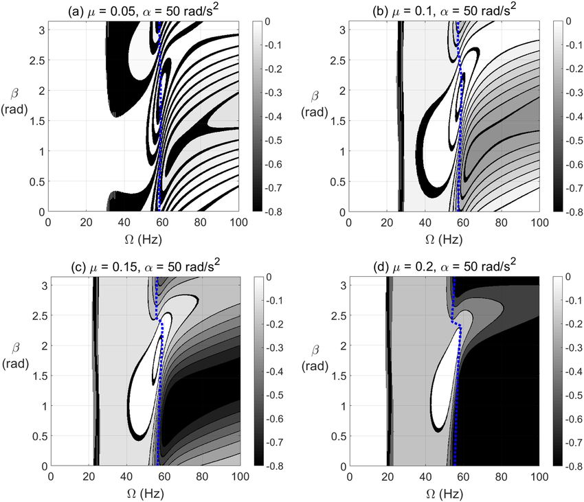
www.nature.com/scientificreports/
Figure 1. Jeffcott rotor with an open crack model.
Figure 2. Schematic diagrams of the open crack in the shaft cross-section (a) before the shaft’s rotation, and (b)
after the shaft’s r otation13–15.
where M , C , and K are the mass, damping and stiffness matrices. The matrices M and K , and the unbalance force
vector F u (t) for steady-state operation of intact Jeffcott rotor system are given, respectively, as
mε�2 cos (�t)
m 0 48E I 0
M= ,K = 3 and F u (t) = (2)
0 m L 0 I mε�2 sin (�t) − mg
where m is the rigid disk mass, L is the length of the shaft, E is the modulus of elasticity of the shaft, I is the area
moment of inertia of the shaft cross-section, is the shaft angular rotational speed and ε is the eccentricity of
the unbalance force mass.
The appearance of transverse crack in the shaft cross-sections is associated with time-varying stiffness matrix
which is represented by K C (t). Therefore, Eq. (1) can be rewritten for a cracked system as
M q̈(t) + C q̇(t) + K C (t)q(t) = F u (t) (3)
Steady‑state operation. Here we consider the open and breathing crack models for studying the potential
energy content in a cracked Jeffcott rotor system at steady-state running.
Open crack model. The transverse open crack model is considered here as shown in Fig. 2. The depth of the
crack in the transverse radial direction is expressed by h. The crack opening orientation at the beginning of
shaft’s rotation is assumed to be at zero angle with respect to the fixed X axis. The unbalance force vector orienta-
tion with respect to the crack opening direction is represented by the angle β as shown.
If the shaft has a transverse open crack as shown in Fig. 2, the stiffness matrix in the rotating centroidal
coordinates x and y axes is written as
48E Iy 0
KR = 3
0 Ix (4)
L
where Iy = Iy − e2 Ace and Ix = Ix are the area moments of inertia with respect to the centroidal rotating coor-
dinates. The quantities Ix , Iy , Ace and e are found for the normalized crack depth µ = h/R in1,13. The cracked
Scientific Reports | (2021) 11:15294 | https://doi.org/10.1038/s41598-021-94836-8 3
Vol.:(0123456789)
www.nature.com/scientificreports/
element stiffness matrix K C (t) with respect to the stationary coordinates is obtained by transforming K R via the
following transformation
K C (t) = Ψ K R Ψ T (5)
where Ψ is the coordinate transformation matrix which is expressed as
cos(�t) − sin(�t)
Ψ =
sin(�t) cos(�t) (6)
Accordingly, the resultant stiffness matrix K C (t) in the stationary coordinates is obtained from Eq. (5) for
the open crack model as
K C (t) = K 1 + K 2 cos (2�t) + K 3 sin (2�t) (7)
where is the constant angular rotational speed. For I 1 = (1/2) Ix + Iy and I 2 = (1/2) Ix − Iy , the matrices
K 1, K 2 and K 3 are obtained from the transformation as
48E I 1 0 48E −I 2 0 48E 0 −I 2
K1 = 3
0 I1
, K2 = 3
0 I2
, and K 3 = 3
−I 2 0 (8)
L L L
Breathing crack model. The breathing crack model in15,30 is also considered here to obtain the time-varying
stiffness matrix K C (t). Therefore, the instantaneous time-varying moments of area in the cracked cross-section
are firstly calculated based on the shaft angle of rotation θ (t) = �t at each time step in the numerical integra-
tion as
(9a)
IX (t) = I − I − I 1 f1 (t)
(9b)
IY (t) = I + I − I 1 f1 (t) − 2I − I 1 − I 2 f2 (t)
p
A1 e2
2θ 2 sin π − kθ 2
I1 − I2
IXY (t) = − + sin (2θ(t)) 2
sin (kθ (t)) (9c)
2 2 π 2 − k2 θ
k=1 2
where f1 (t) and f2 (t) are the crack breathing functions which are given as
� � � � /2)−1 � �
(n� � �
θ (t) 1 n n θ (t)
f1 (t) = cosn (10a)
� �
= n +2 cos n − 2j
2 2 n/2 j 2
j=0
p
1 θ1 + θ2 2
cos (iθ2 ) − cos (iθ1 )
f2 (t) = − cos (iθ (t)) (10b)
π 2 (θ2 − θ1 ) i=1 i2
where θ1 is the angles at which the crack starts to close and θ2 is the angle at which the crack becomes fully close.
The formulas of θ1, θ2, I , I 1, I 2, A1 and e are found in15,30 and provided in the appendix. For crack depths near
to µ = 0.2 or below this value, the values of p and n in Eqs. (9) and (10) are selected to be equal to 16 and 12,
respectively, to guarantee a sufficient convergence of the approximate values of moments of area to the exact
values in the cracked cross-section. Accordingly, the cracked shaft stiffness matrix K C (t) in the fixed centroidal
coordinates for a breathing crack model is now expressed as
KY (t) KXY (t) 48E IY (t) IXY (t)
K C (t) =
KXY (t) KX (t)
= 3
IXY (t) IX (t) (11)
L
Transient operation. Open crack model. For transient operation, the angular acceleration rate during the
shaft rotation significantly alters the system’s mathematical model. The internal material damping is also con-
sidered according t o46 to be proportional to the stiffness matrix K in Eq. (2) of the intact shaft. Accordingly, this
damping content is expressed as DR = ζ K where ζ is the internal viscous damping coefficient. Therefore, the in-
ternal damping matrix DR is transformed into the fixed coordinates using the transformation matrix Ψ which was
previously given in Eq. (6) to obtain the damping force in the fixed coordinates as F D = −ζ K q̇(t) + K cir q(t)
where K cir is the skew-symmetric circulation matrix which is given as
48E 0 −I
K cir = 3
I 0 (12)
L
Accordingly, for the angle of rotation θ (t) = 0.5αt 2 and angular speed �(t) = αt at the angular acceleration
rate α, the stiffness matrix K C (t) in Eq. (3) of the cracked shaft with an open crack model and the damping matrix
C for transient rotation are expressed as
Scientific Reports | (2021) 11:15294 | https://doi.org/10.1038/s41598-021-94836-8 4
Vol:.(1234567890)
www.nature.com/scientificreports/
K C (t) = K 1 + K 2 cos (2θ(t)) + K 3 sin (2θ(t)) + �(t)ζ K cir
(13)
C = γ M + ζKR
where γ is the external viscous damping coefficient which is selected to be γ = 100 s−1 according t o46. In addi-
tion, ζ was usually assumed of order O(10−7 ) for steel shafts in the literature47,48. Therefore, ζ is selected for the
numerical simulation as ζ = 2 × 10⁻⁷ s.
Breathing crack models. Considering the breathing crack model, the stiffness matrix K C (t) of the cracked shaft
is still obtained according to Eqs. (9–11) at θ (t) = 0.5αt 2 and �(t) = αt . Moreover, the term including the
circulation matrix in Eq. (12) should be also maintained in the total stiffness of the cracked shaft with breathing
crack model where the total stiffness becomes K C (t) + �(t)ζ K cir rather than K C (t) in Eq. (3).
During transient operations, the angular acceleration rate α is also affecting the unbalance force vector
components for both open and breathing crack models. Accordingly, by incorporating the angular acceleration
rate and the unbalance force vector angle β of the cracked shaft, the unbalance force vector F u (t) including the
gravity effect at θ(t) = 0.5αt 2 and �(t) = αt is written as
mεα 2 t 2 cos(αt 2 /2 + β) + mεα sin
2
αt /2 +
β
F u (t) =
mεα 2 t 2 sin(αt 2 /2 + β) − mεα cos αt 2 /2 + β − mg
(14)
Effective stiffness calculations
Here, an effective stiffness measure for the considered cracked Jeffcott rotor system at steady-state and transient
operations is introduced based on45. By pre-multiplying the equations of motion in Eq. (3) by q̇T and integrating
for zero initial condition from t = 0 to the steady-state time of operation tss , we obtain
tss tss tss
1 T T T
q̇ M q̇ + q̇ C q̇ dt + q̇ K C (t)q dt = q̇T F u (t)dt (15)
2
0 0 0
Therefore, from this equation we obtain the following representation of the total potential energy in the
cracked rotor system as
t
P(t) = q̇T K C (t)q dt (16)
0
This potential energy in Eq. (14) can be written in the following equivalent form as
1
P(t) = keff (t)z(t)2 (17)
2
where z(t) is the whirl amplitude which is obtained from z(t) = ux (t)2 + vy (t)2 . Accordingly, the effective
stiffness content is obtained as
2P(t)
keff (t) = (18)
z(t)2
Numerical simulation and experimental results
The physical parameters in Table 1 of the Spectra Quest MFS-RDS lab rotordynamic simulator shown in Fig. 3
are employed in the numerical simulation to obtain the potential energy and effective stiffness measures based
on Eqs. (16) and (18). This simulator is employed for experimental validation of the numerical simulation
results where it incorporates a single rigid disk at the mid-span of the shaft as shown. Two proximity probes
were installed near to the rigid disk to collect the experimental data of the horizontal and vertical whirl ampli-
tudes of the system. In addition, the instantaneous shaft rotational speed is automatically collected at the same
proximity probes frequency which is equivalent to 5 kHz. The collected whirl response vector by the proximity
T
probes which is scaled to the mean of data forms the vector of displacements q = [ ux vy ] which is employed
with Eqs. (16) and (18) to obtain the experimental potential energy and effective stiffness values. The resonance
frequency of the experimental configuration is obtained for the crack-free case to be exp ∼ = 57 Hz where the
obtained one from the theoretical crack-free Jeffcott rotor model is JF ∼ = 59 Hz.
Steady‑state response. The response of the cracked rotor system for steady-state operations is obtained
from the numerical integration of Eq. (3) according to the given physical parameters in Table 1 of the considered
cracked system. Therefore, the numerical and experimental whirl amplitudes are obtained for open and breath-
ing crack models. Accordingly, Eqs. (16) and (18) are employed with the numerical and experimental whirl
responses for calculating the potential energy and effective stiffness values.
Open crack model. The unstable zones of shaft rotational speeds are usually dominated by negative potential
and negative stiffness content. The positive potential energy values are set to zero in all contour plots in the paper
Scientific Reports | (2021) 11:15294 | https://doi.org/10.1038/s41598-021-94836-8 5
Vol.:(0123456789)
www.nature.com/scientificreports/

                                             Physical parameter description                  Value
                                             Length of the steel shaft (L)                   700 mm
                                             Radius of the steel shaft (R)                   10 mm
                                             Density of the steel shaft (ρs )                7850 kg/m3
                                             Modulus of elasticity of the steel shaft (E)    2.1 × 10¹¹ N/m2
                                             Mass unbalance (m · e)                          1 × 10⁻⁴ kg · m
                                             Unbalance force angle (β)                       varying
                                             External viscous damping coefficient (γ )       100 s−1
                                             Internal viscous damping coefficient (ζ )       2 × 10⁻⁷ s
                                             Outer radius of the aluminum rigid disk (ro )   150 mm
                                             Inner radius of the aluminum rigid disk (ri )   10 mm
                                             Thickness of the aluminum rigid disk (h)        15 mm
                                             Mass of the aluminum rigid disk                 0.663 kg

                                            Table 1.  Physical parameters of the rotor.

                                            Figure 3.  Spectra Quest MFS-RDS rotordynamic simulator.

                                            to distinguish the negative potential energy zones. In addition, the blue dotted line in all contour plots represents
                                            the resonance forward whirl rotational speeds. Therefore, the effect of crack propagation on negative potential
                                            and effective stiffness during shaft operation at steady-state response is shown in Figs. 4 and 5 for different
                                            unbalance force vector orientations of gravity-free vertical rotor system. It was observed that the crack depth
                                            and unbalance force vector angles have significant impact on the extent and intensity of the negative potential
                                            energy zones. Extended zones of negative potential for wide range of rotational speeds are observed when the
                                            unbalance force angle is between β = π/2 rad and β = π rad as shown in Fig. 5. Therefore, this zone of unbal-
                                            ance force vector angles significantly affects the stability of the cracked system and elevates the severity of crack
                                            propagation. Furthermore, it is also observed that at β = π/6 rad and β = π/3 rad in Fig. 4 and β = 7π/6 rad
                                            in Fig. 5, the negative potential content has the highest levels at µ ≥ 0.25.
                                                To clearly identify the effect of varying β on the level of negative potential rather than the ranges of its extent,
                                            the results are plotted in Fig. 6 for vertical shaft and in Fig. 7 for horizontal shaft configurations, respectively, at
                                            different crack depths. It is observed in these figures that the zones of β values of high levels of negative poten-
                                            tial and stiffness are nearly centered at β = π/4 rad . Therefore, near to this angle the crack propagation has the
                                            highest effect on the stability of the cracked system than other angles. It is also observed that the gravity has less
                                            impact on the negative potential energy content than other parameters as observed in Fig. 6 of vertical system
                                            and Fig. 7 of horizontal system.

                                            Breathing crack model. The effect of breathing crack model on negative potential energy and effective stiffness
                                            zones of the horizontal cracked rotor system for different crack depths, varying unbalance force vector angles
                                            and varying steady-state rotational speeds is shown in Fig. 8. Two major zones of negative potential and stiff-
                                            ness are observed at each crack depth where one of them appear in the pre-resonance zone at high values of β
                                            and the other one appears in the post-resonance zone at low values of β. In addition other extended zones start
                                            to appear in the vicinity of 1/3, 1/2 and 2/3 of the resonance whirl rotational speed as shown. The intensity and
                                            recurrence of these zones are affected by the crack depth as shown. At µ = 0.2, the level of negative potential
                                            energy and stiffness gets very high as shown from the gray-scale colored bar, especially in the neighborhood of
                                            the resonance rotational whirl speed. In addition, at resonance whirl rotational speed, the negative potential
                                            energy content is observed to be dominant. Both open and breathing crack models in Figs. 7 and 8 are associated
                                            with significant negative potential energy zones that appear at pre- and post-resonance rotational speeds. These
                                            zones are strongly affected by the crack depth and the unbalance force vector orientation.

          Scientific Reports |   (2021) 11:15294 |                      https://doi.org/10.1038/s41598-021-94836-8                                                6

Vol:.(1234567890)
www.nature.com/scientificreports/

                                  Figure 4.  Effect of the open crack model depth µ at varying shaft rotational speeds on the potential energy
                                  content in steady-state response at unbalance force angles β = 0 rad in (a), β = π/6 rad in (b), β = π/3 rad in
                                  (c) and β = π/2 rad in (d).

                                  Experimental results. The changes in experimental whirl amplitudes with respect to the shaft rotational speed
                                  are plotted in Fig. 9 for crack depth µ = 0.2 at two different unbalance force vector angles β = 4π/9 rad and
                                  β = 8π/9 rad . The resonance rotational speed is obtained from this figure for β = 4π/9 rad and β = 8π/9 rad
                                  at µ = 0.2 to be exp ∼  = 54.5 Hz where the crack-free one is exp ∼ = 57 Hz . The obtained potential energy and
                                  the corresponding effective stiffness values based on the experimental whirl amplitudes and Eqs. (16) and (18)
                                  are plotted in Fig. 10 for β = 4π/9 rad and in Fig. 11 for β = 8π/9 rad . It is observed in these figures that in
                                  the vicinity of the critical rotational speed exp ∼
                                                                                     = 54.5 Hz significant transitions between positive and negative
                                  effective stiffness values take place with various intensities. These observations are in good agreement with the
                                  numerical simulation prediction in Fig. 7d for both considered unbalance force angles.

                                  Transient response. The response of horizontal cracked rotor system for transient operations is obtained
                                  for Eq. (3) by numerical integration for both open and breathing crack models. Accordingly, the numerical and
                                  experimental whirl amplitudes and velocities are obtained for potential energy and effective stiffness calculations
                                  according to Eqs. (16) and (18).

                                  Open crack model. The effect of open crack propagation and unbalance force vector orientation on the negative
                                  potential energy and stiffness content in the transient response at which a passage through resonance rotational
                                  speed takes place is shown in Fig. 12 for α = 25 rad/s2 and in Fig. 13 for α = 50 rad/s2. It is observed that the
                                  crack depth and unbalance force vector angles have a significant impact on the extent and level of negative
                                  potential and stiffness zones. Wider zones of high negative potential energy are more observed at the post reso-
                                  nance rotational speeds rather than the pre-resonance rotational speeds. These highest levels of negative poten-
                                  tial are observed near to β = π/2 rad at α = 50 rad/s2 and significantly affected by crack depth propagation for
                                  both angular acceleration rates as shown from the gray-scale colored bar.

Scientific Reports |   (2021) 11:15294 |               https://doi.org/10.1038/s41598-021-94836-8                                                   7

                                                                                                                                              Vol.:(0123456789)
www.nature.com/scientificreports/

                                            Figure 5.  Effect of the open crack model depth µ at varying shaft rotational speeds on the potential energy
                                            content in steady-state response at unbalance force angles β = 2π/3 rad in (a), β = 5π/6 rad in (b), β = π rad
                                            in (c) and β = 7π/6 rad in (d).

                                            Breathing crack model. The effect of breathing crack propagation on negative potential and effective stiffness
                                            zones during shaft’s transient operation is shown in Figs. 14 and 15 at α = 25 rad/s2 and α = 50 rad/s2, respec-
                                            tively, for different crack depths and unbalance force vector orientations. It is clearly observed that the crack
                                            depth and unbalance force vector orientation have also a significant impact on the extent and intensity of the
                                            negative potential zones. Extended zones of negative potential for a wide range of rotational speeds are observed
                                            at higher crack depths. The behavior near 1/2, 1/3 and 2/3 of resonance rotational speed of the cracked system
                                            with breathing crack model in transient response in Figs. 14 and 15 is somehow close to that in Fig. 8 for steady-
                                            state response of similar rotor configuration with breathing crack model.

                                            Experimental results. To verify the numerical simulation findings of the accelerated shaft in transient response,
                                            both numerical and experimental whirl responses for horizontal and vertical whirl amplitudes are employed
                                            with Eqs. (16) and (18) for effective stiffness and potential energy calculations. Accordingly, the numerical simu-
                                            lation results of the potential energy content in Fig. 16 are compared with the experimental results for various
                                            values of unbalance force vector angles. It is observed that the zones of rotational speeds at which the potential
                                            energy content is of positive value precede the critical whirl speed zone in both numerical and experimental
                                            results for wide range of unbalance force vector angles. In addition, both numerical and experimental results
                                            show that the post-resonance zone of rotational speeds is dominated by negative potential energy content for all
                                            of the selected values of unbalance force vector angles.
                                                In the shown range of rotational speeds at β = π/9 rad in Fig. 16a, the numerical results only shows negative
                                            potential energy while their corresponding experimental results in Fig. 16g show a narrow zone of positive poten-
                                            tial energy. Similarly, this is also observed at angles β = π/3 rad in Fig. 16c,i and β = 5π/9 rad in Fig. 16e,k.
                                            However, the remaining angles in Fig. 16 shows good agreement between the numerical and experimental results.
                                            This mismatch between some numerical and experimental results at some of the considered unbalance force
                                            angles does not affect the important conclusions stated in the previous paragraph.

          Scientific Reports |   (2021) 11:15294 |               https://doi.org/10.1038/s41598-021-94836-8                                                  8

Vol:.(1234567890)
www.nature.com/scientificreports/
Figure 6. Effect of unbalance force vector angle β at varying shaft rotational speeds on potential energy content
in steady-state response of vertical cracked rotor system with open crack model depths µ = 0.05 in (a), µ = 0.1
in (b), µ = 0.15 in (c) and µ = 0.2 in (d).
Remarks on findings
In the crack-free system, the negative stiffness content has not been captured in both steady-state and transient
operations of the rotor system. However, in all of previous numerical and experimental results for steady-state
and transient operations, it has been observed that the level of negative effective stiffness content is strongly
affected by the transition from the pre-resonance to post-resonance zones of rotational speeds. The cracked
shaft behaves like a buckled beam in its whirl orbit of rotation where the negative stiffness is generated due to
the interaction between the time-periodic or time-varying stiffness content with the unbalance force excitation
at steady-state and transient operations. It can be stated that during the bending of the rotating cracked shaft
in its whirl orbit, the negative effective stiffness could indicate to that the shaft is more capable to further bend-
ing from its centerline. However, for positive effective stiffness the shaft seems to be stiffer for further bending
from its centerline. Accordingly, the shaft during whirling could behave like a compressed static rod at both
ends where bending from its centerline (buckling) takes place under the effect of the unbalance force excitation
rather than end axial loads. Similar to the compressed rod, the shaft tends to resist bending toward its centerline
and tends to be less stiff to bend away from the centerline. Accordingly, at the vicinity of resonance rotational
speed, the negative stiffness content might result in severe vibration whirl amplitudes, leading to failure and
complete damage as the crack keeps its propagation. The potential energy content can be investigated by using
a well-established methodology in real life applications based on the instantaneous vibration data collected in
rotor systems. For example, the vibration data in gas turbine units are collected at each bearing by horizontal
and vertical accelerometers over long periods of running time. Therefore, these data can be processed to obtain
the corresponding velocity and displacement responses for potential energy calculations. These potential energy
calculations can be compared with reference calculations of an intact version of the rotor to observe any change
that suggests cracks propagation.
Scientific Reports | (2021) 11:15294 | https://doi.org/10.1038/s41598-021-94836-8 9
Vol.:(0123456789)www.nature.com/scientificreports/
Figure 7. Effect of unbalance force vector angle β at varying shaft rotational speeds on potential energy content
in steady-state response of horizontal cracked rotor system with open crack model depths µ = 0.05 in (a),
µ = 0.1 in (b), µ = 0.15 in (c) and µ = 0.2 in (d).
Conclusions
The Jeffcott rotor model is considered here to investigate the effect of interaction between the crack depth and
the change in unbalance force vector orientation on potential energy and effective stiffness content in cracked
rotor systems during transient or steady-state operations. The breathing and open crack models at steady-state
and transient operations are considered in this study. The expression of the effective stiffness in the cracked
rotor system has been obtained from direct integration of equations of motion. It has been found that there
is a wide zones of rotational speeds and unbalance force vector angles at which high negative stiffness content
appears in the numerical and experimental whirl responses of the considered crack rotor system. Therefore, the
cracked rotor system in the vicinity of the resonance rotational speeds exhibits high levels of negative stiffness
content where further crack propagation at several unbalance force vector angles put the system at high risk of
rapid failure. The findings in this paper suggests analyzing the potential energy content in cracked rotors whirl
response as a potential damage detection tool.
Scientific Reports | (2021) 11:15294 | https://doi.org/10.1038/s41598-021-94836-8 10
Vol:.(1234567890)www.nature.com/scientificreports/
Figure 8. Effect of unbalance force vector angle β at varying shaft rotational speeds on potential energy content
in steady-state response of horizontal cracked rotor system with breathing crack model depths µ = 0.05 in (a),
µ = 0.1 in (b), µ = 0.15 in (c) and µ = 0.2 in (d).
Figure 9. Experimental whirl amplitudes in steady-state response versus the shaft rotational speeds at µ = 0.2
and β = 4π/9 rad in (a) and β = 8π/9 rad in (b) of the horizontal cracked rotor system.
Scientific Reports | (2021) 11:15294 | https://doi.org/10.1038/s41598-021-94836-8 11
Vol.:(0123456789)www.nature.com/scientificreports/
Figure 10. Experimental results in steady-state response of potential energy content in (a) and the
corresponding effective stiffness content in (b) for varying shaft rotational speeds at µ = 0.2 and α = 25 rad/s2
of the horizontal cracked rotor system.
Figure 11. Experimental results in steady-state response of potential energy content in (a) and the
corresponding effective stiffness content in (b) for varying shaft rotational speeds at µ = 0.2 and α = 25 rad/s2
of the horizontal cracked rotor system.
Scientific Reports | (2021) 11:15294 | https://doi.org/10.1038/s41598-021-94836-8 12
Vol:.(1234567890)www.nature.com/scientificreports/
Figure 12. Effect of unbalance force vector angle β at varying shaft rotational speeds for α = 25 rad/s2 on the
potential energy content in transient response at open crack depths µ = 0.05 in (a), µ = 0.1 in (b), µ = 0.15 in
(c) and µ = 0.2 in (d).
Scientific Reports | (2021) 11:15294 | https://doi.org/10.1038/s41598-021-94836-8 13
Vol.:(0123456789)www.nature.com/scientificreports/
Figure 13. Effect of unbalance force angle β at varying shaft rotational speeds for α = 50 rad/s2 on the potential
energy content in transient response at open crack depths µ = 0.05 in (a), µ = 0.1 in (b), µ = 0.15 in (c) and
µ = 0.2 in (d).
Scientific Reports | (2021) 11:15294 | https://doi.org/10.1038/s41598-021-94836-8 14
Vol:.(1234567890)www.nature.com/scientificreports/
Figure 14. Effect of unbalance force vector angle β at varying shaft rotational speeds for α = 25 rad/s2 on
the potential energy content in transient response at breathing crack depths µ = 0.05 in (a), µ = 0.1 in (b),
µ = 0.15 in (c) and µ = 0.2 in (d).
Scientific Reports | (2021) 11:15294 | https://doi.org/10.1038/s41598-021-94836-8 15
Vol.:(0123456789)www.nature.com/scientificreports/
Figure 15. Effect of unbalance force vector angle β at varying shaft rotational speeds for α = 50 rad/s2 on
the potential energy content in transient response at breathing crack depths µ = 0.05 in (a), µ = 0.1 in (b),
µ = 0.15 in (c) and µ = 0.2 in (d).
Scientific Reports | (2021) 11:15294 | https://doi.org/10.1038/s41598-021-94836-8 16
Vol:.(1234567890)www.nature.com/scientificreports/
Figure 16. Numerical simulation results in (a)–(f) and the corresponding experimental results in (g)–(l) of the
potential energy content in the transient whirl response at different unbalance force angles for α = 25 rad/s2
and µ = 0.2(gray color for positive potential energy values).
Scientific Reports | (2021) 11:15294 | https://doi.org/10.1038/s41598-021-94836-8 17
Vol.:(0123456789)www.nature.com/scientificreports/
Appendix
For breathing mechanism of the crack, the crack is assumed to be fully open position at −θ1 ≤ θ ≤ θ1
range,
partially open at θ1 ≤
θ
< π + φ 2 2 and π − φ 2 ≤ θ < 2π − θ1 ranges, and fully closed at
π + φ 2 2 ≤ θ ≤ 3π − φ 2 2 where φ = tan−1 (s/b) for the shown s and b dimensions in Fig. 2. There-
fore, for the normalized crack depth µ, the quantities in Eqs. (9) and (10) are calculated using the following
equations15,30
π 4
I= R
4
γ = [µ(2 − µ)]1/2
π R4
Ix = R4 + (1 − µ) 2µ2 − 4µ + 1 γ + sin−1 (1 − µ)
8 4
π R4
Iy = R4 − (1 − µ) 2µ2 − 4µ − 3 γ + 3 sin−1 (γ )
4 12
I1 = I − Ix
I2 = I − Iy
(19)
A1 = R2 π − cos−1 (1 − µ) + (1 − µ)γ
2R3 2R3 γ 3
e= [µ(2 − µ)]3/2 =
3A1 3A1
2
I 1 = I1 − A1 e
I 2 = I2
c + R(1 − µ)
θ1 = tan−1 √
R µ(2 − µ)
π
θ2 = + cos−1 (1 − µ)
2
Received: 1 June 2021; Accepted: 19 July 2021
References
1. Al-Shudeifat, M. A. On the finite element modeling of the asymmetric cracked rotor. J. Sound Vib. 332(11), 2795–2807. https://
doi.org/10.1016/j.jsv.2012.12.026 (2013).
2. Jun, O. S. & Gadala, M. S. Dynamic behavior analysis of cracked rotor. J. Sound Vib. 309(1–2), 210–245. https://doi.org/10.1016/j.
jsv.2007.06.065 (2008).
3. Varney, P. & Itzhak, G. Crack detection in a rotor dynamic system by vibration monitoring—Part II: Extended analysis and experi-
mental results. J. Eng. Gas Turbines Power 134(11), 112501. https://doi.org/10.1115/1.4007275 (2012).
4. Kulesza, Z. & Jerzy, T. S. Auxiliary state variables for rotor crack detection. J. Vib. Control 17(6), 857–872. https://doi.org/10.1177/
1077546309360050 (2011).
5. Bachschmid, N., Paolo, P., Ezio, T. & Vania, A. Identification of transverse crack position and depth in rotor systems. Meccanica
35(6), 563–582. https://doi.org/10.1023/A:1010562205385 (2000).
6. Kulesza, Z. & Jerzy, T. S. Rigid finite element model of a cracked rotor. J. Sound Vib. 331(18), 4145–4169. https://doi.org/10.1016/j.
jsv.2012.04.014 (2012).
7. Sekhar, A. S. Vibration characteristics of a cracked rotor with two open cracks. J. Sound Vib. 223(4), 497–512. https://doi.org/10.
1006/jsvi.1998.2120 (1999).
8. Mohiuddin, M. A. & Khulief, Y. A. Dynamic response analysis of rotor-bearing systems with cracked shaft. J. Mech. Des. 124(4),
690–696. https://doi.org/10.1115/1.1423950 (2002).
9. Sekhar, A. S. & Prabhu, B. S. Transient analysis of a cracked rotor passing through critical speed. J. Sound Vib. 173(3), 415–421.
https://doi.org/10.1006/jsvi.1994.1238 (1994).
10. Sekhar, A. S., Mohanty, A. R. & Prabhakar, S. Vibrations of cracked rotor system: Transverse crack versus slant crack. J. Sound Vib.
279(3–5), 1203–1217. https://doi.org/10.1016/j.jsv.2004.01.011 (2005).
11. Prabhakar, S., Sekhar, A. S. & Mohanty, A. R. Transient lateral analysis of a slant-cracked rotor passing through its flexural critical
speed. Mech. Mach. Theory 37(9), 1007–1020. https://doi.org/10.1016/S0094-114X(02)00020-4 (2002).
12. Prabhakar, S., Sekhar, A. S. & Mohanty, A. R. Crack versus coupling misalignment in a transient rotor system. J. Sound Vib. 256(4),
773–786. https://doi.org/10.1006/jsvi.2001.4225 (2002).
13. Al-Shudeifat, M. A. New backward whirl phenomena in intact and cracked rotor systems. J. Sound Vib. 443, 124–138. https://doi.
org/10.1016/j.jsv.2018.11.038 (2019).
14. Al-Shudeifat, M. A., Shiryayev, O., Al Hammadi, F., Alzarooni, T. & Nataraj, C. Post-resonance backward whirl in accelerating
cracked rotor systems. Eur. J. Mech. A Solids 83, 104039. https://doi.org/10.1016/j.euromechsol.2020.104039 (2020).
15. Alzarooni, T., AL-Shudeifat, M. A., Shiryayev, O. & Nataraj, C. Breathing crack model effect on rotor’s post-resonance backward
whirl. J. Comput. Nonlinear Dyn. 15(12), 121007. https://doi.org/10.1115/1.4048358 (2020).
16. Ramesh, B. T., Srikanth, S. & Sekhar, A. S. Hilbert–Huang transform for detection and monitoring of crack in a transient rotor.
Mech. Syst. Signal Process. 22(4), 905–914. https://doi.org/10.1016/j.ymssp.2007.10.010 (2008).
17. Guo, D. & Peng, Z. K. Vibration analysis of a cracked rotor using Hilbert–Huang transform. Mech. Syst. Signal Process. 21(8),
3030–3041. https://doi.org/10.1016/j.ymssp.2007.05.004 (2007).
18. Dong, G. M., Chen, J. & Zou, J. Parameter identification of a rotor with an open crack. Eur. J. Mech. A Solids 23(2), 325–333. https://
doi.org/10.1016/j.euromechsol.2003.11.003 (2004).
19. Collins, K. R., Plaut, R. H. & Wauer, J. Detection of cracks in rotating Timoshenko shafts using axial impulses. J. Vib. Acoust. 113(1),
74–78. https://doi.org/10.1115/1.2930158 (1991).
Scientific Reports | (2021) 11:15294 | https://doi.org/10.1038/s41598-021-94836-8 18
Vol:.(1234567890)www.nature.com/scientificreports/
20. Gounaris, G. D. & Papadopoulos, C. A. Crack identification in rotating shafts by coupled response measurements. Eng. Fract.
Mech. 69(3), 339–352. https://doi.org/10.1016/S0013-7944(01)00076-5 (2002).
21. Dong, G. M. & Chen, J. Crack identification in a rotor with an open crack. J. Mech. Sci. Technol. 23(11), 2964–2972. https://doi.
org/10.1007/s12206-009-0814-5 (2009).
22. Kulesza, Z. Dynamic behavior of cracked rotor subjected to multisine excitation. J. Sound Vib. 333(5), 1369–1378. https://doi.org/
10.1016/j.jsv.2013.10.031 (2014).
23. Kamel, M. & Bauomy, H. S. Nonlinear behavior of a rotor-AMB system under multi-parametric excitations. Meccanica 45(1),
7–22. https://doi.org/10.1007/s11012-009-9213-3 (2010).
24. Eissa, M., Kamel, M. & Bauomy, H. S. Dynamics of an AMB-rotor with time varying stiffness and mixed excitations. Meccanica
47(3), 585–601. https://doi.org/10.1007/s11012-011-9469-2 (2012).
25. Seibold, S. & Weinert, K. A time domain method for the localization of cracks in rotors. J. Sound Vib. 195(1), 57–73. https://doi.
org/10.1006/jsvi.1996.0403 (1996).
26. Mohammed, A. A., Neilson, R. D., Deans, W. F. & MacConnell, P. Crack detection in a rotating shaft using artificial neural networks
and PSD characterization. Meccanica 49(2), 255–266. https://doi.org/10.1007/s11012-013-9790-z (2014).
27. Darpe, A. K. A novel way to detect transverse surface crack in a rotating shaft. J. Sound Vib. 305(1–2), 151–171. https://doi.org/
10.1016/j.jsv.2007.03.070 (2007).
28. Chasalevris, A. C. & Papadopoulos, C. A. Coupled horizontal and vertical bending vibrations of a stationary shaft with two cracks.
J. Sound Vib. 309(3–5), 507–528. https://doi.org/10.1016/j.jsv.2007.07.039 (2008).
29. Papadopoulos, C. A. & Dimarogonas, A. D. Coupled longitudinal and bending vibrations of a rotating shaft with an open crack.
J. Sound Vib. 117(1), 81–93. https://doi.org/10.1016/0022-460X(87)90437-8 (1987).
30. Guo, C. et al. Stability analysis for transverse breathing cracks in rotor systems. Eur. J. Mech. A Solids 42, 27–34. https://doi.org/
10.1016/j.euromechsol.2013.04.001 (2013).
31. AL-Shudeifat, M. A. Stability analysis and backward whirl investigation of cracked rotors with time-varying stiffness. J. Sound Vib.
348, 365–380. https://doi.org/10.1016/j.jsv.2015.03.007 (2015).
32. Galarza-Urigoitia, N. et al. Predictive maintenance of wind turbine low-speed shafts based on an autonomous ultrasonic system.
Eng. Fail. Anal. 103, 481–504. https://doi.org/10.1016/j.engfailanal.2019.04.048 (2019).
33. Gradzki, R., Kulesza, Z. & Bartoszewicz, B. Method of shaft crack detection based on squared gain of vibration amplitude. Nonlinear
Dyn. 98(1), 671–690. https://doi.org/10.1007/s11071-019-05221-0 (2019).
34. Jiang, X., Shi, J., Huang, W. & Zhu, Z. Non-dominated solution set based on time–frequency infograms for local damage detection
of rotating machines. ISA Trans. 92, 213–227. https://doi.org/10.1016/j.isatra.2019.02.023 (2019).
35. Liu, Y. et al. Weighted contribution rate of nonlinear output frequency response functions and its application to rotor system fault
diagnosis. J. Sound Vib. 460, 114882. https://doi.org/10.1016/j.jsv.2019.114882 (2019).
36. Liu, Y., Zhao, Y., Han, J., Meng, Q. & Yao, H. Combination algorithm for cracked rotor fault diagnosis based on NOFRFs and HHR.
J. Mech. Sci. Technol. 33(4), 1585–1593. https://doi.org/10.1007/s12206-019-0310-5 (2019).
37. Bovsunovsky, A. P. Estimation of efficiency of vibration damage detection in stepped shaft of steam turbine. Electr. Power Syst. Res.
154, 381–390. https://doi.org/10.1016/j.epsr.2017.09.012 (2018).
38. Kumar, V. R. & Peng, Q. Nonlinear dynamic modeling of the cracked rotor ball bearing system with emphasis on damage detection
capabilities. J. Vib. Acoust. 140(4), 041018. https://doi.org/10.1115/1.4039404 (2018).
39. Rabelo, D. S. et al. Fault detection of a rotating shaft by using the electromechanical impedance method and a temperature com-
pensation approach. J. Nondestr. Eval. 36(2), 25. https://doi.org/10.1007/s10921-017-0405-9 (2017).
40. Mao, Y., Qin, Y. & Zhang, A. Compound damages detection for rotors by the coupled piezoelectric impedance. IEEE Access 6,
75975–75987. https://doi.org/10.1109/ACCESS.2018.2873659 (2018).
41. Cruz-Vega, I., Rangel-Magdaleno, J., Ramirez-Cortes, J. & Peregrina-Barreto, H. Automatic progressive damage detection of rotor
bar in induction motor using vibration analysis and multiple classifiers. J. Mech. Sci. Technol. 31(6), 2651–2662. https://doi.org/
10.1007/s12206-017-0508-3 (2017).
42. Bovsunovsky, A. & Surace, C. Non-linearities in the vibrations of elastic structures with a closing crack: A state of the art review.
Mech. Syst. Signal Process. 62, 129–148. https://doi.org/10.1016/j.ymssp.2015.01.021 (2015).
43. Kumar, C. & Rastogi, V. A brief review on dynamics of a cracked rotor. Int. J. Rotating Mach. https://doi.org/10.1155/2009/758108
(2009).
44. Nath, A. G., Udmale, S. S. & Singh, S. K. Role of artificial intelligence in rotor fault diagnosis: A comprehensive review. Artif. Intell.
Rev. https://doi.org/10.1007/s10462-020-09910-w (2020).
45. AL-Shudeifat, M. A. & Alhammadi, F. K. Negative effective stiffness content in cracked rotors. ASME Int. Mech. Eng. Congr. Expos.
52033, V04AT06A002. https://doi.org/10.1115/IMECE2018-87470 (2018).
46. Friswell, M. I., Penny, J. E. T., Seamus, D. G. & Arthur, W. L. Dynamics of Rotating Machines (Cambridge University Press, 2010).
47. Zapoměl, J. & Ferfecki, P. A computational investigation on the reducing lateral vibration of rotors with rolling-element bearings
passing through critical speeds by means of tuning the stiffness of the system supports. Mech. Mach. Theory 46(5), 707–724. https://
doi.org/10.1016/j.mechmachtheory.2010.12.006 (2011).
48. Zapoměl, J. & Ferfecki, P. A computational investigation of the disk-housing impacts of accelerating rotors supported by hydro-
dynamic bearings. J. Appl. Mech. 78(2), 021001. https://doi.org/10.1115/1.4002527 (2011).
Author contributions
M.A.-S. contribution was in the concept, numerical simulation analysis and the matlab codes, experimental
results analysis and the related matlab codes, writing the paper. F.A. contribution was in doing experiments,
writing and formatting the paper.
Funding
The authors are grateful for the support provided by Khalifa University of Science and Technology for support-
ing this research.
Competing interests
The authors declare no competing interests.
Additional information
Correspondence and requests for materials should be addressed to M.A.A.-S.
Reprints and permissions information is available at www.nature.com/reprints.
Scientific Reports | (2021) 11:15294 | https://doi.org/10.1038/s41598-021-94836-8 19
Vol.:(0123456789)www.nature.com/scientificreports/
Publisher’s note Springer Nature remains neutral with regard to jurisdictional claims in published maps and
institutional affiliations.
Open Access This article is licensed under a Creative Commons Attribution 4.0 International
License, which permits use, sharing, adaptation, distribution and reproduction in any medium or
format, as long as you give appropriate credit to the original author(s) and the source, provide a link to the
Creative Commons licence, and indicate if changes were made. The images or other third party material in this
article are included in the article’s Creative Commons licence, unless indicated otherwise in a credit line to the
material. If material is not included in the article’s Creative Commons licence and your intended use is not
permitted by statutory regulation or exceeds the permitted use, you will need to obtain permission directly from
the copyright holder. To view a copy of this licence, visit http://creativecommons.org/licenses/by/4.0/.
© The Author(s) 2021
Scientific Reports | (2021) 11:15294 | https://doi.org/10.1038/s41598-021-94836-8 20
Vol:.(1234567890)You can also read