Model SDHmini Instruction Manual Dewpoint Meter 3006 - SDHmini User Manual - Iss 1.1 - Shaw Moisture Meters
←
→
Page content transcription
If your browser does not render page correctly, please read the page content below
Model SDHmini
Dewpoint Meter

Instruction Manual
3006 - SDHmini User Manual - Iss 1.1

Contents
1   Introduction ................................................................................ 5
        1.1 Unpacking Your Shaw Moisture Meters SDHmini ................ 5
        1.2 General Description ............................................................. 5
2   Important Information ................................................................ 6
        2.1 Symbols Table ...................................................................... 6
        2.2 Lithium-ion Cell - Battery ...................................................... 6
        2.3 Pressure Exposure ................................................................ 7
3   Installation .................................................................................. 7
        3.1 Gases to Avoid ..................................................................... 7
        3.2 Installing the Air/Gas Sampling System ............................... 7
        3.3 Piping Installation Schematic ............................................... 8
        3.4 Piping Schematic Component Index .................................... 9
        3.5 Purging the Sample Connection .......................................... 9
        3.6 Using the SDHmini to Take a Moisture Reading ................ 10
        3.7 Desiccant Dry-Down Technology ....................................... 11
        3.8 Sample Connections .......................................................... 11
        3.9 Pressure and Flow Control ................................................ 12
        3.10 Particulate Contamination ............................................... 12
        3.11 Liquid Contamination ...................................................... 12
4   Normal Operations ................................................................... 13
        4.1 Powering On/Off ............................................................... 13
        4.2 Graphical Viewing Options ................................................ 13
        4.3 Display Options .................................................................. 13
        4.4 Choice of Units .................................................................. 14
5   Calibration ................................................................................ 15
        5.1 Auto Calibration (AutoCal) ................................................ 15
        5.2 Calibration Setpoint (CalSet) ............................................. 16
        5.3 Calibration Procedure Error Messages .............................. 17
6   Sensor Related Settings ............................................................. 17
        6.1 Sensor Type ....................................................................... 17
        6.2 Selecting Gas Types ........................................................... 17
        6.3 Selecting Gas Molecular Weights ...................................... 18
        6.4 Pressure ............................................................................. 18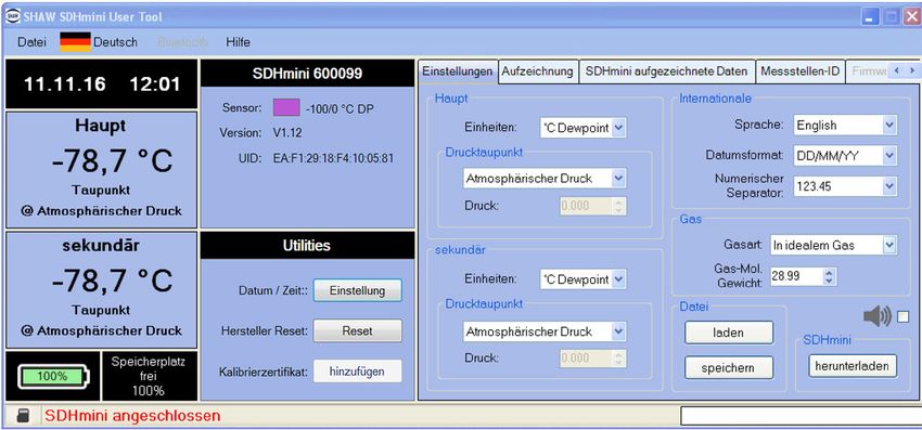
Contents
7    Non Measurement Related Configuration Functions ................. 19
         7.1 Changing the Date ............................................................. 19
        7.2 Changing the Time ............................................................. 19
         7.3 Changing International Settings ........................................ 19
         7.4 Hotkeys .............................................................................. 20
8    Installing the SDHmini User Tool ............................................... 21
        8.1 Extracting the SDHmini User Tool Software from the USB
             Flash Drive (Memory Stick) ................................................ 21
        8.2 Extracting the SDHmini User Tool Software from the
              Instrument .......................................................................... 22
9    Connecting the SDHmini and SDHmini User Tool ...................... 24
10   Using the SDHmini User Tool .................................................... 25
         10.1 Menu items ...................................................................... 25
             10.1.1 File - SDHmini Report ............................................... 25
             10.1.2 Language .................................................................. 25
             10.1.3 Help .......................................................................... 26
        10.2 Instrument Live Reading ................................................... 26
         10.3 Instrument Static Information .......................................... 26
         10.4 Utilities ............................................................................. 27
         10.5 Settings ............................................................................. 28
         10.6 Firmware Update ............................................................. 29
         10.7 Factory Reset .................................................................... 30
11   Additional Information ............................................................. 31
         11.1 Desiccant and Head Seal Replacement ........................... 31
         11.2 Temperature .................................................................... 32
         11.3 Response Time ................................................................ 32
        11.4 Guarantee ........................................................................ 32
         11.5 Basic Definitions .............................................................. 32
        11.6 Problem Guide ................................................................. 33
12   SDHmini Specifications .............................................................. 34
13   SDHmini General Assembly Diagram ......................................... 35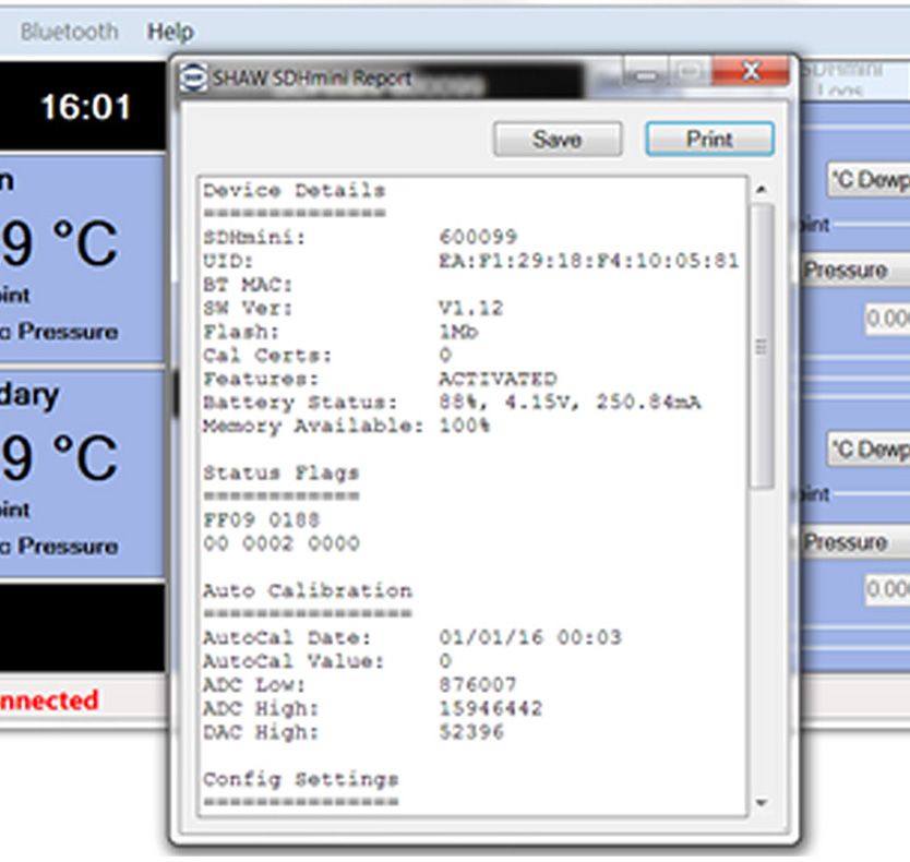
1 Introduction
1.1 Unpacking Your Shaw Moisture Meters SDHmini
Please examine the SDHmini package for any damage or mishandling. If any
damage is evident please notify the carrier and the Shaw Moisture Meters
representative from where this unit was purchased.
You should have received (if ordered):
● 1 model SDHmini instrument ● 1 AC/DC adaptor
● 1 carry case ● 1 pressure dewpoint circular
● 1 Allen key calculator
● 1 two metre length of PTFE tubing ● 1 USB flash drive with SHAW
● 1 USB charging cable SDHmini User Tool software
● 1 Fir Tree fitting plus 1 x fittings as ● 1 instruction manual
ordered
If anything is missing please contact your distributor immediately.
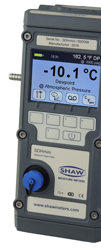
1.2 General Description
The SDHmini is a micro-controller based battery operated dewpoint hygrometer
with state of the art features and enhancements with support of USB for
communicating with PC.
It is a fully, self-contained unit incorporating the moisture sensor, signal
conditioning circuitry, memory management, graphics display, membrane
keyboard, real time clock, on-board battery and charger circuit.
The graphical user interface features three main viewing screens, digital, graphical
(historical readings in a scrolling strip chart) and a meter (a traditional moving
coil). There is also a secondary display in the top right which allows display of
readings in alternative units of measurement.
The unit operates with the following 10 language options: English, German,
French, Spanish, Portuguese, Russian, Italian, Chinese, Japanese and Korean.
A full colour graphics LCD display with 320 x 240 resolution landscape and a 6 key
input including an on/off key.
The displayed units can be changed on both the primary and secondary displays for
the selectable moisture unit e.g. °C, °F, g/m3, ppm(v), ppm(w) and lb/MMSCF.
5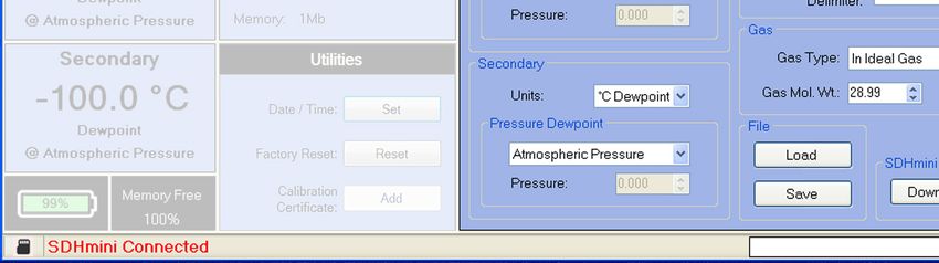
The SDHmini settings can be adjusted by a user-friendly software interface
    incorporating multiple menus, hot key combinations, information displays and
    control functions.

    Use the supplied USB cable, attach between the PC and the instrument, an
    automatic connection over USB is established.
    The USB port allows:
             ● Charging of the battery (Li-ion) when connected to PC or dedicated
               power supply
             ● Downloading of new firmware to the unit
             ● Downloading of setup data from dedicated PC software

    The view panel allows access to many of the features, settings and information
    pages within the instrument.

    A micro SD card is fitted to the instrument, the contents of which can be explored
    by clicking the SD card icon in the bottom left of the view panel. The contents may
    include user manuals, service notes, calibration data sheets, firmware backups etc.

    2 Important Information
    2.1 Symbols Table
              2.2 Lithium-ion Cell - Battery
                  The SDHmini is powered by a single lithium-ion cell. The cell is not
                  field replaceable by the user as it is completely enclosed within the
                  instrument. However, the cell may be exchanged by an authorised
                  agent who has received the necessary training, support systems
                  and accreditation. It is recommended to only use the USB power
                  supply supplied with the instrument.
                  It is recommended that the SDHmini be put on charge overnight
                  when the unit is first received.
                  To attain maximum cell life, the SDHmini should always be charged
                  at room temperature. The discharging cell life (hours of use from a
                  fully charged cell) will reduce when used in cold conditions. Switch
                  on the instrument to check if fully charged.
                  The symbol indicates that the device contains a battery which may
                  be charged via the USB connector.
                  Rating of instrument is less than 1 W in operation. Charging
                  voltage is 5 V nominal.

6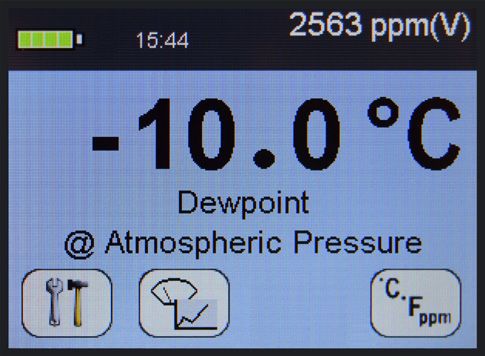
2.3 Pressure Exposure
      !                The maximum pressure to which the telescopic
                      measuring head is exposed should not be more than

                                         0.3 bar, 4 psi
                     Exposing the measuring head to higher pressures may
                       damage the instrument and result in injury to the
                           operator or other personnel in the area.

3 Installation
3.1 Gases to Avoid
The SHAW moisture sensors are suitable for many different industrial and research
applications. Most gases can be checked for their moisture content with no need
for the calibration to be altered when changing between different gases, as the
sensor operates only with reference to the water vapour content.
There are however, some gases that must be avoided as they are not compatible
with the material of construction of the sensor. Ammonia (NH3), Ozone (O3) and
Chlorine (Cl2) must be avoided at all times, even in small quantities. Hydrogen
Chloride (HCl) also attacks the sensors very quickly. Some, less aggressive acidic
gases such as Sulphur Dioxide (SO2) can be monitored as long as the moisture
content is low, generally less than 100ppm(v). If in doubt, please ask your supplier.
Sulphur Hexafluoride (SF6) has no effect on the sensor. If the gas has been exposed
to arcing, however, it is possible that various acidic species will have been formed
that will corrode the sensor. When testing SF6 that may have been arced, therefore,
an acidity test should be carried out first; if the gas proves to be acidic then the
moisture test should not be carried out.

3.2 Installing the Air/Gas Sampling System
The Piping Installation Schematic diagram (see section 3.3) shows all components,
which could be used in a dry gas measurement application. Although not all the
items shown will be required for every installation.
The main principle when considering the presentation of the gas sample to the
SDHmini dewpoint meter is to keep the sample system as simple as possible and
of minimum swept volume, so that it has the least possible influence on the gas
sample.

                                                                                        7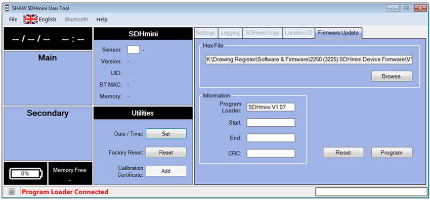
The SDHmini should be placed on a stable surface prior to connecting to the
    sample pipework. Care should be taken to ensure that the sample presented to the
    SDHmini is not contaminated with any component that will damage, contaminate
    or affect in a way that will impair the unit’s accuracy.
    The flow rate, although not critical to the sensor measurement, should be low
    enough to avoid abrasion to the sensor surface without being so low as to extend
    the SDHmini response time to an unacceptable level. In general, a flow rate of
    between 2 and 5 litres/min at normal temperature and pressure will give the right
    balance.
    The SDHmini is designed to operate at atmospheric pressure with a maximum of
    0.3 bar.

    3.3 Piping Installation Schematic

                                    5            6
                     4                                             7

             3                                                                           9
                                                                            8

         2

        1

              MAIN            Notes
                              a. The sample point should be on the upper surface of the horizontal
             PROCESS             pipe or from a vertical section of pipe, wherever possible.
               LINE           b. The sample tube should run upwards from the sample point. If
                                 this is not possible, then an inspection port or drain tap should be
                                 installed at the lowest point in the sample system.

8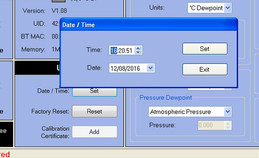
3.4 Piping Schematic Component Index

    1. Sample Isolation Valve - This is a recommended item as it allows access to
       the sample system without interrupting the main process line.
    2. Filter Unit – A filter unit is recommended when the samples are likely
       to contain particulate matter. If the air/gas sample contains heavy
       hydrocarbon condensate, the filter must be of the coalescing type with a
       drain. The filter unit should be positioned as close to the sample point as
       practical.
    3. Sample Tube – This should be stainless steel for dry air or gas applications
       but copper or carbon steel can be used where wetter gases are to be
       measured. If any section of the sample tube must be flexible then PTFE
       should be used. In most cases, 3 mm OD (⅛”) is sufficient as it provides
       good system response time with minimum flow. 6 mm OD (¼”) tube can
       be used where pressure drops across the 3 mm tube are too high.
    4. Pressure Reduction Valve or Pressure Regulator – the sample is measured
       at atmospheric pressure requiring that valve 4 is fitted to the system.
    5. Flow Control Valve.
    6. Sample Connection.
    7. SDHmini.
    8. Flow Indicator – The recommended sample flow is 2 to 5 L/min.
    9. Sample Exhaust – The exhaust is vented to atmosphere or returned to an
       atmospheric pressure line.

3.5 Purging the Sample Connection
Refer to the Piping Installation Schematic in section 3.3.

It is advisable to carry out an initial purge of the sample loop without connecting
the instrument, in order to avoid the possibility of sensor damage on start-up.

Open the sample isolation valve (1) slowly, until there is a small flow of air/gas at
atmospheric pressure from the pressure reduction valve (4). Allow the air/gas to
exhaust through the sample connection (9).

Continue this for two minutes to remove any residual moisture from the sample
pipe work and components. Check that no liquid or particulate contamination,
which could damage the sensor, is passing through the sample pipe. Directing the
sample onto a piece of white paper (such as a filter paper) will make it easier to
see any dust or oil mist in the sample.

                                                                                        9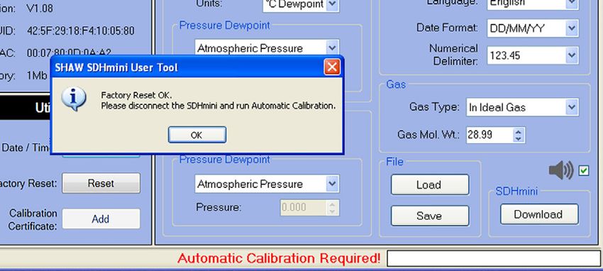
Connect the SDHmini. The SDHmini is not flow sensitive, however, the sample
     flow needs to be enough to fill the sensor head with gas effectively, so anything
     less than 1 litre/min would mean that the instrument would take too long to settle
     to a stable reading. The flow should not be so high that the gas velocity could
     physically damage the sensor or cause back-pressure in the sensor head, so should
     not exceed approximately 10 litres/min.

     3.6 Using the SDHmini to Take a Moisture Reading

     The first purpose of the SDHmini is to provide a rapid, easy and reliable means of
     carrying out moisture content measurement of gases. To ensure rapid response
     the sensor is kept dry by surrounding the sensor with desiccant in the head
     assembly when it is not in use.

     After purging the system to be monitored fit the SDHmini sample pipe to the
     sample connection (6). Allow the gas to purge for a further two minutes with the
     head down. Restrict the outlet of the SDHmini (7) by placing a finger over the
     sample exhaust (9), so that the pressure of the sample lifts the telescopic head.
     As soon as the head is fully extended remove the finger, to prevent pressure build
     up. Pull gently on the head to make sure it is fully extended. If there is not enough
     pressure to lift the head assembly, assist it by pulling it up, do this very slowly so
     that ambient air is not drawn in through the outlet.

     The sensor will respond to the moisture level present in the sampled gas. The
     displayed moisture value will continue to change until the sensor reaches
     equilibrium at which point the displayed value is representative of the moisture
     level in the sampled gas. When a reading has been taken and the test is finished,
     push down the telescopic head fully, carefully turn off the sample flow and
     disconnect the sample pipe. With the head in the down position the desiccant will
     dry the sensor, ready for the next test.

     Note: It is important that the head assembly is either fully up or fully down to
     keep the desiccant isolated from the ambient air so avoiding wetting it. When the
     instrument is not in use it should be stored with the head in the down position.

10
3.7 Desiccant Dry-Down Technology
The unique design Sensor surrounded by desiccant The desiccant and
allows purging of the ensuring it is dry, ready for the sensor are always
gas in the “Dry-Down next measurement. isolated from
Position” which will atmospheric air to
bring all surfaces and ensure an accurate
voids to equilibrium. reading.
Sensor exposed
to gas sample.
Sample exhaust
Sample gas
inlet pipe Sensor
Dry-Down Position Read Position
Keeping the sensor dry between tests ensures that the SDHmini is ready to carry
out rapid spot checks. The unique design of the desiccant head achieves this by
surrounding the sensor with desiccant, keeping the sensor dry. The head is then
lifted for sampling, exposing the sensor to the sample gas.
Between tests the sensor is not allowed to come into contact with ambient air. The
chamber is designed so that the void space and chamber wall surfaces are purged
with sample gas before exposure of the sensor, giving faster, more accurate and
reliable results.
3.8 Sample Connections
The SDHmini is supplied with two connections: a Fir Tree on one side and a Swagelok
compression fitting for ¼”, ⅛”, 6 mm OD pipe or another Fir Tree fitting (as specified
on your order) on the other. Either can be used as the inlet connection (6).
PTFE and stainless steel are recommended materials for sample pipes. Some specialist
flexible tubing may be suitable as sample pipe but common flexible tubing such as
PVC, nylon, polythene or rubber, should not be used, as they are permeable and
water vapour from the atmosphere will diffuse through them into the sample gas.
A 2 m PTFE sample pipe is supplied for use with the Fir Tree connection. The first
time this is used it is advisable to warm the end that will go over the Fir Tree for a few
seconds with a heat source to soften it slightly, which helps to get a gas tight seal.
113.9 Pressure and Flow Control
In most cases the gas to be sampled will be at a positive pressure, which will need
to be reduced to atmospheric pressure. At low pressures, up to around 8 barg, this
can be done by including a simple needle valve (5) to control the flow and thereby
the pressure dropping across it. Ideally this would be the isolation valve (1) on the
sample point, thus keeping the number of joints and glands, which are points of
potential moisture ingress to a minimum.
At higher pressures it is advisable to reduce the pressure across a pressure
regulator (4). Any regulator used should be stainless steel and of a low swept
volume. Typical laboratory or welding type regulators are not suitable because
they have elastomeric diaphragms which are permeable to water vapour and the
high swept volume will be slow to purge.
3.10 Particulate Contamination
If the sample gas is likely to contain particulate material this should be kept away
from the sensor by including a small inline particle filter (2) in the sample system.
If the surface of the sensor becomes partly coated with particles it will not affect
the calibration of the sensor but will restrict the movement of water molecules
across the surface so increasing the time it takes for the sensor to come to
equilibrium with the water vapour concentration around it. If the solid material is
hygroscopic, such as desiccant dust, whenever there is a change in the moisture
concentration in the sample, this material must come to equilibrium with the
moisture content before the sensor can respond to the change, which will cause
delays in obtaining accurate results.
3.11 Liquid Contamination
If the sample gas may contain liquid contamination, such as oil mist, this should
be kept away from the sensor by including a coalescing filter or an appropriate
membrane filter (2) in the sample system.
If the surface of the sensor becomes partly coated with liquid, again, it will
not affect the calibration of the sensor. It will restrict the movement of water
molecules across the surface so increasing the time it takes for the sensor to
come to equilibrium with the water vapour concentration around it. If the liquid is
hygroscopic, such as glycol, the buffering effect described for desiccant dust may
be so great that the sensor becomes too slow to use.
124 Normal Operations
4.1 Powering On/Off
To switch on (and off), press , the SDHmini
briefly displays a splash screen showing instrument
status, error information and firmware version number.
4.2 Graphical Viewing Options
The start up screen is soon replaced by the normal measurement mode screen
(see below) displaying the current moisture measurement in a variety of views.
The last used or last selected mode will be utilised automatically.
Top Bar Top Bar
Battery Status - Time Secondary Display or
Measurement Value
Viewing Portal
Main display resides here
but can also show alternative Button Icon Area
Measurement Data, These are soft keys which
Information Screens and are always visible to assist
Configurations in a variety of users in navigating through
formats. the graphical screens.
4.3 Display Options
The display can be changed by pressing the following keys to cycle
through all of the graphical views and will take you to the home screen.
Here is a view starting as a digital number followed by simulated strip chart and
moving coil instruments.
The digital display mode has the benefit of showing the moisture measurement
in main choice of engineering units but also a secondary display with perhaps
alternative engineering units. This mode also allows application of pressure
dewpoint to evaluate the measurement in other samples pressures.
134.4 Choice of Units
In normal measurement mode. The secondary display is the measurement
A
displayed in the top bar on the right hand side (A). It allows alternative
engineering units or concentrations to be displayed
alongside those chosen in the main display.
To choose the engineering units to be displayed, select the
units key from the main digital view.
You will be presented with the following screen to select engineering units for the
main and secondary displays. You may toggle between adjusting the main and
secondary displays by pressing the key 3.
Use the key to move to the desired
measurement type and press to
select it. Pressing will exit the
current screen without making any
further changes. B
Here the secondary display is being
changed to ppm(v) engineering units
(B).
C
Please note: when you change the
display to either the moving coil meter or
the strip chart the secondary engineering
units display is replaced with the primary
units (C).
This continues to allow high precision measurement whilst having the benefit of
the graphical display.
5 Calibration
Field calibrations of the SDHmini may be performed periodically, every two to three
months, to ensure accuracy between laboratory calibrations by checking the span
of the instrument and correcting for any deviation. These functions can be used to
verify operation of the SDHmini if confirmation of an unexpected result is required.
This may be accomplished by two similar in built calibration functions, namely
AutoCal and CalSet.
145.1 Auto Calibration (AutoCal)
The AutoCal facility uses the fact that each sensor is designed and manufactured
to give no further increase in response when it reaches its maximum moisture
level. For example a SDHmini with a full scale value of 0 °C dewpoint will read
0 °C dewpoint when exposed to a gas with this moisture concentration and will
continue to read 0 °C dewpoint as the moisture concentration rises above 0 °C
dewpoint.
The SDHmini can therefore be adjusted to read 0 °C dewpoint on any gas with a
moisture concentration wetter than 0 °C dewpoint, ambient air for instance, thus
setting the span to match the original calibration.
NOTE: For instruments with a dewpoint range above 0 °C, e.g. the Blue range, -80 to +20 °C,
please refer to section 5.2 Calibration Setpoint (CalSet).
Select AutoCal from the Configuration Menu.
Please ensure that the inlet and outlet valves are open to
atmosphere.
Extend the desiccant head on the instrument (as illustrated on
the instrument screen) noticing that the value of the full scale
moisture level has already been automatically preselected as a
target of 0 °C. You may need to lift the head two to three times
to allow ambient air through to the chamber, ensuring inlet
and outlet are unrestricted. Press .
The SDHmini will display a moving bar until it assesses that
the sensor has stabilised (please allow up to ten minutes for
this to occur).
The SDHmini will now display the full scale value of the unit,
either -20 °C or 0 °C depending on the sensor range.
Close the desiccant head when instructed to do so and press
.
15Pressing during the AutoCal aborts the process.
Press to accept.
The value present at the start of the aborted AutoCal process
is reinserted.
The SDHmini will return the instrument to normal measurement mode.
Note: Avoid carrying out the AutoCal procedure on a SDHmini with a full scale value of 0 °C
dewpoint on days when the ambient may be below this value, for example a dry day when
the ambient temperature is below approximately 12 °C.
The entered AutoCal value must not be pressure compensated.
5.2 Calibration Setpoint (CalSet)
The function CalSet is suitable for sensors with an upper
range limit of +20 °C dewpoint, for example the Blue range
-80 to +20 °C dewpoint, where this upper range limit will
exceed typical ambient conditions.
The unit may be checked against a known moisture
level, for example from a moisture generator or other
reference standard, such as a chilled mirror hygrometer or a
psychrometer using the function CalSet.
Select CalSet from the Configuration Menu.
Extend the desiccant head and press .
Whether the instrument is being checked against the
measured ambient level or against a known calibration
standard from a moisture generator, and are used
to set the value accordingly.
Selecting +10 °C for instance involves changing the sign and
number by use of both keys.
The entered CalSet value must not be a pressure
compensated one and must be within the range of the
sensor.
Press when done.
16The SDHmini will display a moving bar until it assesses that
the sensor has stabilised (up to 10 minutes).
The full scale value, 10 °C dewpoint, is now displayed.
Press when complete.
Close the desiccant head when instructed and press .
Pressing during CalSet aborts the process and the value
present at the start of the aborted CalSet process is reinserted.
Press to continue/accept changes.
The SDHmini will return to the normal
operational mode.
5.3 Calibration Procedure Error Messages
If the instrument fails calibration, a message will be displayed on the screen until
acknowledged by the user, e.g.
AutoCal Failed
Sensor Open Circuit
or
AutoCal Failed
Sensor Short Circuit
This will mean replacing the sensor or its interconnecting cable in some cases.
6 Sensor Related Settings
On the Configuration screens there exists a collection of measurement settings
associated with the sensors and its environment.
6.1 Sensor Type
Here you may view the type of sensor
installed in the SDHmini and its range.
6.2 Selecting Gas Types
The SDHmini default setting is for ideal gas behaviour, however, there is an option
to change the setting
to natural gas which
uses the appropriate
calculation.
176.3 Selecting Gas Molecular Weights
The SDHmini default setting is for air (molecular weight 28.99), however, this
function allows the molecular weight to be set appropriately for other sample
gases, for example 18.99 .
6.4 Pressure
This sub-menu has, for both the primary and secondary displays, five options
allowing the user to select either atmospheric pressure or one of four pressure
engineering units and applied pressure.
When this function is selected, the main and secondary display screens will display
the pressure at which the dewpoint reading is calculated.
The SDHmini requires that a numerical pressure value be entered in the selected
units at the bottom of the units selection section, for example selecting pressure
dewpoint of 2,000 psig on secondary display.
Warning: This function is purely an internal calculation and DOES NOT allow an
elevated pressure to be applied to the measuring head.
187 Non Measurement Related Configuration Functions
7.1 Changing the Date
In order to change the present date press the arrow key
to select the Date function from the Configuration menu.
Press .
Use and to change the date.
Here for example the date is changing from 06/03/15 to 06/04/15.
Press to enter new date or to abort changes.
7.2 Changing the Time
In order to change the present time
press to select the Time function
from the Configuration menu.
To change the time use and .
Here for example the time is changing from 10:48 to 11:48.
Press to enter new time or to abort changes.
7.3 Changing International Settings
Use the selection cursor to select options to change the
settings for Language, Date Format and Numerical Delimiter.
Select International Settings from the Configuration Menu.
To change the Language option select .
The language choice area is highlighted. A flag of a country
most associated with one of the pre-installed languages
indicates which language is currently selected. The
19SDHmini operates with the following 10 language options:
English, German, French, Spanish, Portuguese, Russian,
Italian, Chinese, Japanese and Korean.
Use the to select the flag required.
And to accept the choice.
The Date Format i.e. DD/MM/YY or MM/DD/YY is also chosen
from within the International Settings menu.
And finally, numbers can be presented 123.45 or 123,45.
Note: These settings are carried through to any data files and
printer outputs where appropriate.
7.4 Hotkeys
To access the hotkeys from the main screen, press key 5 on the keypad.
The four soft keys are replaced by a new set of hotkeys for a short while. These are
available for rapid access to certain areas of the menu structures or functions.
Turns ON and OFF the inbuilt sounder
Accesses the alternative moving coil graphical viewing screen
Takes the user to the Information screen
If the SDHmini is connected to a PC then the second hotkey is replaced
by an SD card symbol
208 Installing the SDHmini User Tool
The SDHmini User Tool software allows the instrument to be connected to a PC,
enabling easy configuration of the SDHmini settings and functions.
Please note: For the best visual appearance it is recommended that the PC display
text and icons option is set to default rather than medium or larger.
In order to install the software the user must ensure that they have the
permissions to do so from their respective manager or IT systems manager.
Users with limited permissions in the Windows environment also may find that
they might not be able to install software until administrative privileges are set.
On installation the software will only work on Windows version XP (SP3), Vista,
7, 8 and 10 and requires Microsoft .NET 3.5. Once installed this software is
warranted not to need any access to the internet or any other sort of network
activities. However there are two links on the Help/About Menu item which if
used on a non-connected PC will not function. If you have a more up-to-date
version of Microsoft .NET you may need to enable v3.5 via the Windows features/
control panel.
There are two ways to install the SDHmini User Tool software.
• From the supplied USB flash drive (memory stick)
• From the instrument’s memory card
8.1 Extracting the SDHmini User Tool Software from the USB Flash
Drive (Memory Stick)
To install
• Insert the USB flash drive in to the PC.
• On your PC open the “my computer” or “computer” folder (the folder title will
depend on which Windows Operating System you are running).
21• Click on the folder or removable disk. The instrument serial number
e.g. 123456 and folder title should match.
• This saves the User Tool Setup to the PC.
• Open the folder for the SHAW SDHmini User Tool Setup software.
• Double click the SHAW SDHmini User Tool Setup icon and install via the
Windows wizard.
• Select installation folder to save your software download in your chosen folder
on the PC.
• Once the installation is complete a dialogue box will appear saying “Installation
Complete”. A shortcut icon will appear on the desktop. Close the dialogue box.
• Safely remove the USB flash drive from your PC.
8.2 Extracting the SDHmini User Tool Software from the
Instrument
To install
• Connect the USB cable provided to the instrument and
PC.
• Switch on the instrument.
• Press key 5 on the instrument to access the hotkeys and
you will see the SD card symbol (key 2).
• Press key 2 on the instrument and the SD card symbol
screen will appear.
• On your PC open the “my computer” or “computer”
folder (the folder title will depend on which Windows
Operating System you are running).
• Click on the folder or removable disk. The instrument number, e.g. 123456, and
folder title should match.
22• This saves the SHAW SDHmini User Tool Setup to the PC.
• Open the folder for the SHAW SDHmini User Tool Setup software.
• Double click the SHAW SDHmini User Tool Setup icon and install via the
Windows wizard.
• Select “Installation Folder” to save your software download in your chosen
folder on the PC.
• Once the installation is complete a dialogue box will appear
saying “Installation Complete”.
A shortcut icon will appear on the desktop. Close the dialogue
box.
• Safely remove the hardware by disconnecting the USB cable
from the unit. You will need to disconnect the USB cable from
the unit to disable the SD card mode on the unit.
239 Connecting the SDHmini and SDHmini User Tool
Always ensure the USB cable is connected to the instrument and PC when
working in the SDHmini User Tool software. If you have not connected the unit
to the PC and attempt to start using the SDHmini User Tool software it will show
a “Not Connected” message.
Please note: Once connected to the SDHmini User Tool software, all keys on the
instrument keyboard are unusable, all changes are made through the User Tool.
Double click the desktop icon to get started.
Switch on the instrument and connect the USB
cable from the unit to the PC. A splash screen appears on
the PC.
On your PC open the SDHmini User Tool. The view panel
appears on the PC saying “SDHmini Connected”.
The instrument will display the following screen to show
that the instrument is connected to the PC.
2410 Using the SDHmini User Tool
10.1 Menu items
The menu strip contains the following options: file, language and help.
10.1.1 File - SDHmini Report
The opportunity for reports to show the
current status and error flags. A report at
the current time can only be printed or
saved but not amended.
If there are any errors, the unit should
be returned to the distributor or you
may perform a factory reset. Please
contact your distributor for advice
before proceeding with a factory reset.
10.1.2 Language
The flag/language menu item shows the ten languages available which can be
reset/amended on the SDHmini User Tool software screen. Note: This does not
change the language on the instrument. To change the language on the instrument
please follow the instructions Changing International Settings in section 7.3.
2510.1.3 Help
The help menu item displays the manufacturer’s contact details and version
number of the software.
10.2 Instrument Live Reading
Displays information regarding:
• Date and time
• Live reading in main units
• Live reading in secondary units
• Battery status
10.3 Instrument Static Information
Displays information regarding:
Instrument serial number
Sensor
Sensor range – moisture sensor
colour and dewpoint range in °C
Version
Firmware version
name or number
UID
Unique instrument
number – an electronic serial
number unique to each instrument
2610.4 Utilities
Date/Time – Set Factory Reset – Reset
The date and time can be set Warning: Performing a factory reset
via the PC. will erase all saved settings and data.
If continuing with the Factory Reset
option, a dialogue box “Auto Calibration
Required” will appear. Please refer to
section 5.2 Auto Calibration (AutoCal)
of the instrument’s instruction manual.
Calibration Certificate – Add
Useful for users to enter the
last calibration check date
after a factory calibration.
Date/Time: Click on Set in the
Utilities panel to reset the
date and time.
The time and date can
be selected manually or
automatically synchronised
with your PC. To save the new
settings, click “Set”.
Once you have selected “Set”
a dialogue box will appear,
“Downloaded OK”. Click OK to
complete.
2710.5 Settings
The Instrument Settings panel allows changes to the following features, which
are explained further in the relevant instruction manual:
International
• Language (on the instrument)
• Date format
• Numerical delimiter – from “.” to “,”
Main and Secondary Displays Gas
• Engineering units • Gas type
• Pressure dewpoint • Gas molecular weight
• Pressure
File
• Loads files to the instrument that
contain already set parameters and Sounder/buzzer
is particularly useful for the multiple Can be selected and
setup of instruments deselected for the
• Save – save settings to a PC file to instrument.
enable uploading for future use
SDHmini
Click download to apply
all/any changes to the
instrument that are made
in this screen.
2810.6 Firmware Update
From time to time in the life cycle of the instrument, a number of product
improvements or updates in the firmware will be made available. The facility
exists for the user to update their instrument without having to return to the
manufacturer.
The firmware update file will be sent via email. Please save the firmware update
file (*.hex) from the email in a location on your PC.
• Please ensure the instrument is switched on.
• Press the power button and key 4 for 2-3 seconds. The
Program Loader will time out after 30 seconds if not used.
• Plug in the USB cable. Please Note: On first time use,
Windows will load a driver for this Program Loader facility.
• Note: the Firmware Update tab is now accessible and there is a “Program
Loader Connected” message in the bottom strip.
• Click Browse for the previously saved firmware update (*.hex) file.
• Click Program. Do not unplug the USB cable throughout this process.
The progress bar will show the following messages:
• “Erasing Memory”
• “Programming Memory”
• “CRC OK”
• Click Reset to return to the instrument main screen
and you will see the message “Program Loader Reset”
in the progress bar.
• Reset the time and date - see section 10.4 Utilities
2910.7 Factory Reset
A factory reset can be performed using the Reset button within the Utilities
panel in the SDHmini User Tool software.
Click Reset and you will see the
following messages.
• “Formatting memory”
• “Creating file system”
• “AutoCal required”
Warning:
Performing a factory
reset will erase all
saved settings and
data and default the
following to factory
settings: date
format, language, main display units, secondary display, gas weight, gas type,
AutoCal value and numerical delimiter.
Please contact your distributor for advice before proceeding with a factory reset.
If continuing with the factory reset option, a dialogue box “Auto Calibration
Required” will appear. Please refer to section 5.2 Auto Calibration (AutoCal).
3011 Additional Information
11.1 Desiccant and Head Seal Replacement
• Unscrew the four handle retaining screws using a hex socket drive.
• Unscrew the four posidrive countersunk screws which hold the retaining
ring to the SDHmini.
• The desiccant filled desiccant chamber can now be removed from the
sample chamber by fully retracting the desiccant chamber. Gently pulling
on the desiccant chamber a little more, will pull the retaining ring out of
the sample chamber. The sample chamber is still retained within the body
of the SDHmini.
• Carefully place the knurled section of the desiccant chamber top section
with the desiccant base assembly uppermost.
• Fully unscrew the desiccant head base assembly turning it anticlockwise.
The desiccant head base may require slight loosening by placing in a soft
jaw vice before this step is carried out. Do not fully unscrew with desiccant
chamber base section at the bottom, as this will spill desiccant.
Only use soft jaws. Do not use tools or vice with hard jaws.
• There is no need to remove the retaining ring from the desiccant chamber
top section except perhaps to change an O-ring.
• Dispose of used desiccant and refill with new, up to a level of 3 mm from
the bottom of the screw thread.
• Insert the desiccant chamber base assembly back into the refilled
desiccant chamber top section. Remember to ensure that the retaining
ring is in place and in the correct orientation prior to reassembly by re-
tightening the threaded parts.
Only use soft jaws. Do not use tools or vice with hard jaws.
• Insert desiccant head and retaining ring back into the sample chamber
pushing down squarely and firmly to push past the resistance of the O-ring
at the top of the sample chamber.
• Push the desiccant chamber back into the sample chamber.
• Align the countersunk holes in the retaining ring to the holes in the
housing and sample chamber within.
• Reattach and tighten the four countersunk screws using the posidrive
screwdriver.
• Reattach the handle using the four cap head M4 screws and the hex drive.
3111.2 Temperature
Typical ambient variations experienced throughout the world are quite
acceptable but avoid placing the instrument in direct sunlight or near a source of
radiant or convected heat. In countries that experience extremes of temperature,
always carry out the automatic calibration with the instrument at its operating
temperature.
11.3 Response Time
The response time of any water vapour pressure detector will naturally be very
much quicker from dry to wet, than from wet to dry. This is the reason that the
SDHmini is so successful. The sensor is kept in a dry condition when it is not in
use and therefore results are obtained in the quickest possible time.
To check whether a particular instrument is within specification, carry out
the automatic calibration procedure, close the instrument head and note the
reading ten minutes later. If the unit has not dried down to -40 °C after this ten
minute period, the instrument should be returned to your supplier/authorised
distributor for examination.
11.4 Guarantee
All products are guaranteed for two years from the date of purchase, some
exclusions are as follows:
Removing protective guard from any sensor, subjecting sensor to shock or black
list gases e.g. caustic and acidic gases like ammonia and chlorine, tampering with
any internal electronics, subjecting to excessive flow rate, contaminants and
general misuse.
If you suspect a fault which you feel needs to be attended to under guarantee
please contact us for assistance hopefully to help fault find and effect a remedy
and if this is not successful, to give precise instructions for the return for
inspection.
No equipment will be replaced or repaired without having been returned for
inspection either to ourselves or an authorised distributor.
11.5 Basic Definitions
Water Vapour Pressure
The pressure exerted by the water vapour contained in any mixture of gases. The
total pressure exerted by the gas mixture is the sum of the pressures exerted by
its components – including the water vapour. Water Vapour Pressure varies in
direct proportion to the total gas.
32Dewpoint Temperature
The temperature to which the gas must be cooled in order that it should be
saturated with water vapour (i.e. 100% relative humidity). For practical reasons it
is referred to dewpoint above 0 °C and frostpoint below 0 °C.
Parts Per Million by Volume
ppm(v) is the ratio of the water vapour pressure to the total gas pressure.
Parts Per Million by Weight
ppm(w) is the ratio of the molecular weight of water vapour to the molecular
weight of the carrier gas mixture.
11.6 Problem Guide
Fault Explanation Required Action Notes
Unit does not turn on. Battery low level. Connect a battery
Screen remains blank charger unit for
and back light off. a minimum of 12
hours charging.
AutoCal failure. Sensor sensitivity Repeat AutoCal. If AutoCal fails,
too low. contact supplier
to replace sensor.
Unit always reads Sensor cable Repair cable.
lower limit. broken.
Unit will not dry down Sieve wet. Perform service on Service Kit
to lower limit. unit using Service available from
Kit. supplier.
‘O’ ring failure. Perform service on Service Kit
unit using Service available from
Kit. supplier.
Battery has short life Battery reaching Return to supplier/ Order from
between charges. end of life. authorised supplier.
distributor
for battery
replacement/
exchange.
Keypad damaged. Check function Contact supplier.
of keypad
electrically.
3312.0 SDHmini Specifications
Accuracy: ±2 °C (±3.6 °F) dewpoint
Type: Battery powered hygrometer complete with carrying case. For
use with desiccant chamber for rapid readings.
Dimensions: 97 mm (w) x 211 mm (h (259 mm head extended)) x 147 mm (d)
3.8 in (w) x 8.3 in (h (10.2 in head extended)) x 5.8 in (d)
Weight: 1.75 kg (3.8 lbs)
Display: Full colour graphics LCD. 320 x 240 resolution. Three main
viewing - digital, graphical and a traditional moving coil.
Secondary display in the top right for display of readings in
alternative units of measurement.
Sensor Connection: Internal
Power Supply: Single lithium-ion cell.
Sampling: Pressure: Atmospheric with flow rate of 2 - 5 litres/minute.
Operating Temperature: -20 °C to +50 °C (-4 °F to +122 °F)
Storage Temperature: -30 °C to +70 °C (-22 °F to +158 °F)
Operating Humidity: 95% RH non-condensing
Calibration: AutoCal on all (but Blue range)
Accessories/Options: Sample System, Service Kit
Sensor Type (r): Sensor Range
Purple (P): -100 °C to 0 °C dewpoint, 0 - 6000 ppm(v)
Red (R): -80 °C to -20 °C dewpoint, 0 - 1000 ppm(v)
Grey (G): -80 °C to 0 °C dewpoint, 0 - 6000 ppm(v)
Blue (B): -80 °C to +20 °C dewpoint, 0 - 23000 ppm(v)
Silver (S): -100 °C to -20 °C dewpoint, 0 - 1000 ppm(v)
Gold (Gl): -110 °C to 0 °C dewpoint, 0 - 6000 ppm(v)
Sensor: Operating Principle: SHAW Ultra High Capacitance Aluminium
Oxide Sensor
3413.0 SDHmini General Assembly Diagram
FRONT VIEW REAR VIEW
259 mm with head extended
211 mm with head extended
SIDE VIEW
TOP VIEW
97 mm
147 mm
13 mm
353006 SDHmini User Manual - Iss 1.1 © SHAW MOISTURE METERS UK (LTD) 2021 Shaw Moisture Meters (UK) Ltd. | Len Shaw Building | Bolton Lane | Bradford | BD2 1AF | England t. +44 (0)1274 733582 | f. +44 (0)1274 370151 | e. mail@shawmeters.com | www.shawmeters.com
You can also read