Mitigation of Power Quality Problems Using Custom Power Devices: A Review
←
→
Page content transcription
If your browser does not render page correctly, please read the page content below
Indonesian Journal of Electrical Engineering and Informatics (IJEEI)
Vol. 5, No. 3, September 2017, pp. 207~235
ISSN: 2089-3272, DOI: 10.11591/ijeei.v5i3.296 207
Mitigation of Power Quality Problems Using Custom
Power Devices: A Review
Miska Prasad*, Ashok Kumar Akella
National Institute of Technology, Jamshedpur, India
e-mail: 2013pgphdee05@nitjsr.ac.in
Abstract
Electrical power quality (EPQ) in distribution systems is a critical issue for commercial, industrial
and residential applications. The new concept of advanced power electronic based Custom Power Devices
(CPDs) mainly distributed static synchronous compensator (D-STATCOM), dynamic voltage restorer
(DVR) and unified power quality conditioner (UPQC) have been developed due to lacking the performance
of traditional compensating devices to minimize power quality disturbances. This paper presents a
comprehensive review on D-STATCOM, DVR and UPQC to solve the electrical power quality problems of
the distribution networks. This is intended to present a broad overview of the various possible
DSTATCOM, DVR and UPQC configurations for single-phase (two wire) and three-phase (three-wire and
four-wire) networks and control strategies for the compensation of various power quality disturbances.
Apart from this, comprehensive explanation, comparison, and discussion on D-STATCOM, DVR, and
UPQC are presented. This paper is aimed to explore a broad prospective on the status of D-STATCOMs,
DVRs, and UPQCs to researchers, engineers and the community dealing with the power quality
enhancement. A classified list of some latest research publications on the topic is also appended for a
quick reference.
Keywords: power quality, voltage sag, voltage swell, distributed static compensator, voltage source
inverter, Z-source inverter, current source inverter, DVR, UPQC
1. Introduction
Nowadays electrical power quality is a very important issue in the electrical distribution
system. It has been always a challenging task to maintain the power quality within acceptable
levels [1-11]. In general, power quality disturbances that affect the voltage and current wave-
forms quality are imbalances, harmonics, flickers, voltage sags and swells [12-17]. PQ problems
can lead to poor power quality which may occur because of increased losses, undesirable and
abnormal nature of equipment, problem of interference etc [18-21].
To develop dynamic, flexible and adjustable solution to the electrical power quality
disturbances, passive L-C filters [22-24], active power filters (APFs) [25-29], hybrid filters [30]
and custom power devices (CPDs) [31-36] are used from time to time.
This paper focuses on a DSTATCOM, DVR and UPQC type compensating custom
power devices. The CPDs mainly DSTATCOMs, DVRs and UPQCs are the APF family
members connected in shunt, series and a combination of shunt and series to achieve superior
control over different power quality disturbances simultaneously.
This paper is intended to present a comprehensive survey of previous research on
DSTATCOM, DVR and UPQC type custom power devices for power quality enhancement in
power distribution network. Over 200 publications [11-218] are seriously reviewed to classify
them in different categories.
The D-STATOM, DVR and UPQC type custom power device are categorized based on
the (1) type of converter topology (voltage source converter and current source converter); (2)
supply system (single-phase two-wire, three-phase three-wire and four-wire).
Therefore, this paper is presented as follows: The state of the art of D-STATCOM, DVR
and UPQC are presented in section 2, section 3 illustrates the classification of custom power
devices (D-STATCOM, DVR and UPQC). Section 4 describes the control methodologies and
approaches including the derivation of reference signal and current/voltage control techniques.
Section 5, latest trends and technical consideration on CPDs are discussed; finally, section 6
discusses the conclusion part of the paper.
Received April 21, 2017; Revised July 10, 2017; Accepted August 5, 2017
208 ISSN: 2089-3272
2. DSTATCOM, DVR and UPQC: State Of The Art
Electrical power quality (EPQ) problems are an issue that is becoming increasingly
important to all levels of usage such as industrial, commercial and utilities. The power quality
issues include short-term events such as voltage sags, swells or even transients with duration of
less than a few seconds. Power system harmonic and flicker issues also fall into the category of
power quality (PQ), even though these issues tend to occur much longer intervals than sags
and transients [11]. Table 1 shows the various power quality problems and their causes. The
authors [12-16] discussed voltage sag and its characteristics in detail. M.R.Alam et al. [17]
proposed an algorithm for detection; classification and characterization of voltage sag and swell
in electricity networks, using three-phase voltage ellipse parameters. The proposed method
employs the instantaneous magnitude of three-phase voltage signals in three axes, which are
separated from each other by 120º.
From time to time different efforts have been carried out to provide an active and
flexible solution to mitigate power quality disturbances. Before the advent of active filters,
passive filters based on inductors and capacitors [22-24] were used and still used in many
power transmission and distribution applications, but it has various disadvantages such as
instability, fixed compensation, resonance with supply as well as loads and utility.
To overcome these drawbacks active power filters (APFs) have been used [25-29].
However, they are costly options for power quality enhancement because their ratings are
sometimes very close to full load (up to 80%) in typical applications.
To face the power quality problems and increase the reliability, an advanced power
electronic based devices have launched over last decades. These power electronic based
devices are called Custom power devices (CPDs) [31-36]. N.G.Hingorani [7] introduced the
concept of custom power. Custom power solution can be network reconfiguration type or
compensation type as shown in Figure1. In this paper, a comprehensive review of
compensating type is presented [9]. The compensating custom power devices are used for
active filtering, load balancing, voltage regulating (sag/swell), harmonic elimination and power
factor correction. These devices are either connected in shunt or in series or a combination of
both and also called D-STATCOM, DVR and UPQC.
D-STATCOM: D-STATCOM is the most important solid state shunt connected CPD. It
has been widely used to precisely regulate system voltage, improve voltage profile, reduce
voltage harmonics, reduce transient voltage disturbances and load compensation. D-STATCOM
controller can be constructed based on both voltage source inverter topology and current
source inverter (CSI) topology [11], [20], [37], [38] as shown in Figure 1. In practice, CSI
topology is not used for D-STATCOM because higher losses on the DC reactor of CSI
compared to the DC capacitor of VSI [39]. The authors [40], [41] proposed reverse blocking
insulated gate bipolar transistor has eradicated the need for the series diode and making CSI a
good alternative. The principal of generating instantaneous active and reactive powers by D-
STATCOM is shown in Figure 2. In Figure 2, voltages and currents are represented with
instantaneous space vectors obtained using a power invariant Clarks transformation. Figure 3
are presented in three cases: the general one, for reactive power equal to zero and for active
power equal to zero. Form the Figure 3 it is clear that by generating an appropriate AC voltage it
is possible to generate arbitrary instantaneous vectors of both active and reactive power. [11]
The authors in [37], [42-44], [45-47] discuss the various aspects such as modeling, design and
simulation for reactive power compensation, unbalanced and harmonic compensation and
voltage regulation (sag/swell). In [9], [48], a D-STATCOM model is used for feasibility and
validating the design. K.R. Padiyar [10], H. Fugita et al. [49], Arya et al. [50] discussed D-
STATCOM for voltage regulation in detail.
IJEEI Vol. 5, No. 3, September 2017 : 207 – 235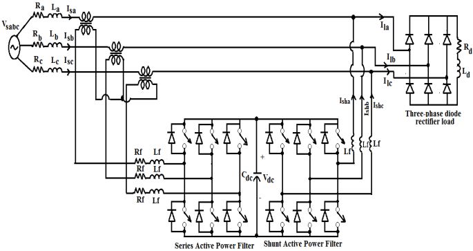
IJEEI ISSN: 2089-3272 209
VT VT VT
Tr Tr Tr
IC IC IC
LF LF LF
VC VC VC
DSTATCOM DSTATCOM DSTATCOM
VSI CSI ZSI
VDC L1
LD
CD C2 C1
L2
Figure 1. Schematic Diagram of VSI, CSI and ZSI based DSTATCOM
Figure 2. Operating Principle of DSTATCOM (a) General Case (b) Reactive Power Zero and (c)
Active Power Zero
DVR: A dynamic voltage restorer (DVR) is a power electronic (PE) converter-based
CPD, which can protect sensitive loads from all supply-side disturbances other than outages. It
is connected in series with a distribution feeder as shown in Figure. 3 and also is capable of
generating or absorbing real and reactive power at its AC terminals. The basic principle of a
DVR is simple: by inserting a voltage of the required magnitude and frequency, the DVR can
restore the load-side voltage up to the desired amplitude and waveform even when the source
voltage is either unbalanced or distorted [11]. A typical location in the distribution system and
the operating of the DVR is shown in Figure.3. The different aspects such as modeling, design
and simulation for harmonic elimination, voltage flicker suspension [9], voltage sag and swell
mitigation are reported in [51-54]. A.K.Jindal et al. [55] highlighted dynamic voltage restorer for
voltage regulation function.
IL
Line Impedance
Load
VS
Supply
Filter circuit
L
Storage C C
unit
PWM Inverter
L
DVR
Figure 3. Basic Structure of DVR
UPQC: For enhancing power quality in the system and protecting sensitive loads a
universal solution can use by an integration of the series-parallel active power filters called
UPQC as depicted in Figure 4.UPQC is a flexible device that can compensate almost all types
Mitigation of Power Quality Problems Using Custom Power Devices… (Miska Prasad)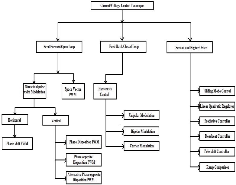
210 ISSN: 2089-3272
of PQ disturbances related to voltage and current simultaneously. Shunt active power filter is
the most promising to tackle the current-related problems such as current harmonics, current
unbalance, reactive current whereas, the series APF is the most suitable to overcome the
voltage-related problems such as voltage harmonics, voltage unbalance, voltage flicker, voltage
sag and swell.
In operating principal, UPQC is a union of shunt and series APFs with two VSI-based
common self-supporting DC bus. The shunt APF is controlled in a current controlled mode such
that it produces a current that is equal to the set of the reference current as produced by the
control algorithm of UPQC.
VL
VS
VInj
IL
Supply
Voltage IComp
Load
LC filter
L1
C2 C1
L2
Series Shunt
Inverter Inverter
Figure 4. Schematic Diagram of UPQC
i t =i*s t -iL t (1)
sh
*
where ish ( t) , is ( t) , i L (wt) represents the shunt APF current, reference source current and
load current. Shunt active power filter should inject a current to eliminate the harmonics
produced by a nonlinear load.
The series active power filter is controlled in voltage control mode such that it generates
a voltage and injects in series with line to achieve a sinusoidal and distortion free voltage at the
load terminal. In the case of voltage sag (VS) condition, series APF should inject a voltage to
maintain the load voltage.
Vsc t = VL* t -Vs t (2)
*
where Vsc ( t) , VL ( t) , Vs ( t) represents the series APF voltage, reference load voltage and
source voltage. The system modeling aspects of the UPQC are reported in [56-63]. In [64], a
mathematical modeling and design of a versatile UPQC are discussed clearly. A.Ghosh et al.
[65] discussed the application of UPQC for voltage regulation in critical loads.
Table 1. Some Effects of Power Quality Problems for the Different Voltage Events
Broad Specific Typical Characteristics Disturbance Consequence
Classification Classification
Duration Magnitude
1. Transients Insulation failure.
1.1 Impulsive 50 ns- 1ms < 6 kV Reduced Lifetime of
transformers and motors
1.2 Oscillatory 5 µs-0.3 ms 0 – 4 pu
2.Short 2.1. Interruption 10 ms – 3 min < 1% Disconnection.
duration
variations 2.2. Sag 10 ms – 1 min 1 - 90% Disconnection of
sensitive loads. Fail
functions.
IJEEI Vol. 5, No. 3, September 2017 : 207 – 235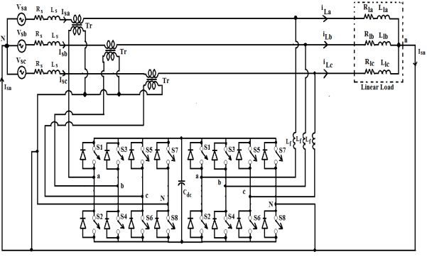
IJEEI ISSN: 2089-3272 211
2.3. Swell 10 ms – 1 min 110 - 180%
Disconnection of
equipment may harm
equipment with
inadequate design
margins
Disconnection of
3. Long sensitive loads. Fail
duration 3.1 Under Voltage > 1 min 80-90% functions.
variations Disconnection of
equipment may harm
3.2 Over Voltage > 1 min 160-120% equipment with
inadequate design
margins
4. Curve 4.1 Harmonics Stationary 0- 20% Extended heating. Fail
distortion function of electronic
equipment
Voltage quality for
5. Voltage overloaded phase. Over
Unbalance ___ Stationary 0.5 - 2% load and noise from 3-
phase equipment.
Ageing of insulation. Fail
6.Voltage ___ Intermittent 0.2 - 7% function. flicker
Fluctuation
3. Classification of Custom Power Devices (D-STATCOM, DVR AND UPQC)
In this section, classification of compensating type custom power devices is given. As
shown in Figure.5, a pictorial view for the classification of custom power devices. The custom
power devices are mainly classified in two main categories: (1) based on converter topology and
(2) based on supply system.
Figure 5. Classifications of CPDs
Mitigation of Power Quality Problems Using Custom Power Devices… (Miska Prasad)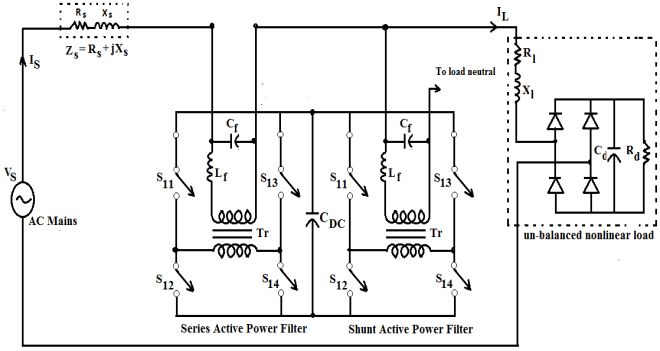
212 ISSN: 2089-3272
3.1. Based on Converter Topology
This D-STATCOM, DVR and UPQC type custom power devices can be constructed
based on voltage source inverter (VSI) topology, current source inverter (CSI) topology [11] and
Z-source inverter topologies.
Figure 6 (a-c) depicts single-line representation of a CSI based D-STATCOM, DVR and
UPQC system configuration [18], [20], [21]. The D-STATCOM, DVR and UPQC may be
constructed using a pulse width modulated (PWM) current source inverter (CSI) [27], [28], [37-
41], [66-70] which uses an inductor LDC as a common energy storage to form the DC link. In
practice, D-STATCOM, DVR and UPQC based on current source inverter are not used due to
high cost, higher losses, [20], [39], and also it cannot find its application in multilevel
configurations. The second topology is based on VSI, which is the most common and popular
inverter topology can be used in D-STATCOM, DVR and UPQC system configurations [9], [20-
26], [29- 36], [42-65], [70-218].
(a)
(b)
(c)
Figure 6. CSI-Based (a) DSTATCOM (b) DVR and (c) UPQC
IJEEI Vol. 5, No. 3, September 2017 : 207 – 235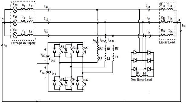
IJEEI ISSN: 2089-3272 213
Figure 7(a-c) shows the configurations of D-STATCOM, DVR and UPQC based on
voltage source inverter (VSI) and Figure 8(a-c) shows the Z-source inverter based
configurations.
The VSI-based topology has the advantages over CSI-based topology include cheaper,
flexible overall control, no need of blocking diodes and capable of multilevel operation [18].
A.Ghosh et al. [9] explained a CSI is usually more reliable and fault tolerant than a VSC
because the large series inductor limits the rate of rise of current in the event of a fault.
However, CSIs have higher losses because of the need to store energy by circulating current in
the inductors which are lossier than capacitive energy storage. Since capacitors are more
efficient, smaller and less expensive than inductors, VSIs are most commonly used in D-
STATCOM, DVR and UPQC system configurations.
(a)
(b)
(c)
Figure 7. VSI-Based (a) DSTATCOM (b) DVR and (c) UPQC
Mitigation of Power Quality Problems Using Custom Power Devices… (Miska Prasad)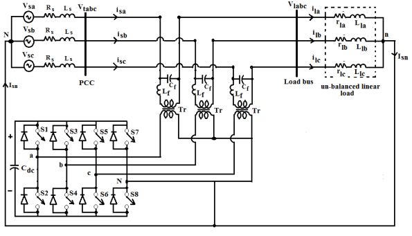
214 ISSN: 2089-3272
Vt VL
RS XS IL
IS
R1
Lf PCC
AC
VS L1
Mains X1
S11 S13
C2 C1 Cd Rd
Tr
L2 S12 S14
Un-balanced
nonlinear load
(a)
Vt VL
RS XS IL
IS
To load
neutral R1
Lf PCC
AC
VS L1
Mains X1
S11 S13
C2 C1
L2 S12 S14
Un-balanced
nonlinear load
(b)
RS XS IL
IS
Lf R1
Lf To load
AC VS
Mains L1 neutral
X1
S11 S13 S11 S13
C2 C1 Cd Rd
Tr Tr
S12 S14 S12 S14
L2
Un-balanced
nonlinear load
(c)
Figure 8. ZSI-Based (a) DVR (b) DSTATCOM and (c) UPQC
3.2. Based On Supply System
To mitigate the power quality disturbances in power distribution system different D-
STATCOM, DVR and UPQC configurations are introduced and they can be divided based on
the type of the supply system topology. In general, AC supplies or loads on the power system
can be mainly classified into single-phase two-wire (1p2w) and three-phase three-wire (3p3w)
and four-wire (3p4w) source. The supply voltage related power quality problems have similar
characteristics for single-phase and three-phase systems. In addition, three-phase systems
need voltage unbalance compensation capability to provide enhanced power quality (PQ). The
load current harmonics and reactive current are the major limitations for a single-phase system.
For the case of three-phase three-wire (3p3w), one must need to consider current unbalance
apart from the reactive and harmonics current.
3.2.1. Single-phase two wire (1p2w) compensating devices
Single-phase two-wire (1p2w) systems are used in all three modes as shunt (D-
STATCOM) [71-74], series DVR [75-83] and a union of both as UPQC [84-101].
IJEEI Vol. 5, No. 3, September 2017 : 207 – 235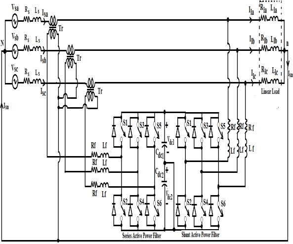
IJEEI ISSN: 2089-3272 215
Figure 9 (a-c) shows the most popular DSTATCOM, DVR and UPQC configurations
consist of two H-bridge inverters [72-74], [83], [84], [86- 97], [99], [101] in single-phase two-wire
(1p2w) system to compensate the power quality (PQ) issues by injecting current in case of D-
STATCOM, voltage in case of DVR and both in the case of UPQC of the electrical power
distribution system.
Figure 10(a-c) shows the most commonly used D-STATCOM, DVR and UPQC
configuration to consists of 3-leg inverters [102] in single-phase two-wire (1p2w) system to
mitigate the power quality (PQ) disturbances by injecting current, voltage and both current and
voltage.
Figure 11(a-c) depicts the most popularly use D-STATCOM, DVR and UPQC system
configuration which consists of half-bridge inverters [85], [98], [100], [103] in single-phase two-
wire (1p2w) system to compensate the power quality (PQ) problems by injecting current in case
of D-STATCOM, voltage in case of DVR and both in the case of UPQC of the electrical power
distribution system.
(a)
(b)
(c)
Figure 9. Two H-bridge (a) DVR (b) DSTATCOM and (c) UPQC
Mitigation of Power Quality Problems Using Custom Power Devices… (Miska Prasad)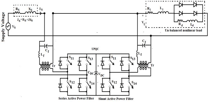
216 ISSN: 2089-3272
(a)
(b)
(c)
Figure 10. 3-Leg (a) DVR (b) D-STATCOM and (c) UPQC
IJEEI Vol. 5, No. 3, September 2017 : 207 – 235IJEEI ISSN: 2089-3272 217
Figure 11. Half-Bridge (a) DSTATCOM (b) DVR and (c) UPQC
3.2.2. Three-phase three wire (3P3W) Compensating devices
Three-phase three-wire (3p3w) nonlinear loads such as adjustable speed drives
(ADSs), frequency converter, current regulator, arc welding drives/machines and arc furnace
causes several power quality (PQ) problems such as voltage sag, swell, harmonics etc. . Most
widely preferred and suitable three-phase three wire (3p3w) voltage source converter (VSC)-
based D-STATCOM , DVR and UPQC network configurations are shown in Figure 12 (a-c) and
are widely reported in literature [56-60], [70],[104-118], [119-130], [131-179].
Mitigation of Power Quality Problems Using Custom Power Devices… (Miska Prasad)218 ISSN: 2089-3272
(a)
(b)
(c)
Figure 12. Three-phase Three-Wire (a) DVR (b) DSTATCOM and (c) UPQC
3.2.3. Three-phase four-wire (3p4w) compensating devices
A large number of single-phase (1-ϕ) loads may be supplied from three-phase (3-ϕ)
mains with a neutral conductor. They cause excessive neutral current, harmonics and reactive
power burden. To reduce the neutral current in a three-phase four-wire (3p4w) system [180-
183], various D-STATCOM, DVR and UPQC configurations have been applied, mainly two split
capacitor (2C), four-leg (4L ) and three H-bridge (3HB) configurations. The first one uses three
H-bridge voltage source converters (VSCs) and these H-bridges are connected through
isolation transformers. The split capacitor topology and four-leg topologies are looking similar.
The fundamental difference between these two topologies is the number of power
semiconductor devices and the connection of the neutral wire.
IJEEI Vol. 5, No. 3, September 2017 : 207 – 235IJEEI ISSN: 2089-3272 219
3.2.3.1. Three H-bridge topology
Figure 13 a-c shows the three-phase four-wire (3p4w) D-STATCOM, DVR and UPQC
system configuration based on three H-bridge (3HB) topologies in three-phase four wire
distribution system and are reported in [65],[184-193]. Three H-bridge (3HB) topology consists
of three single-phase (1-ϕ) H-bridge (full bridge) voltage source inverter (VSI) tied with a
common self supporting DC bus [194]. The main advantage of this topology is the control can
be done either as a three-phase (3-ϕ) unit or three separate single-phase (1-ϕ) units. The
maximum voltage that appears across each H-bridge is the single phase voltage and not the
three-phase voltage as in the case of capacitor midpoint or four-leg topology.
(a)
(b)
(c)
Figure 13. Three-Phase Four-Wire Three H-bridge (a) DVR (b) DSTATCOM and (c) UPQC
3.2.3.2. Three-phase four-wire split capacitor (2C) topology
The split capacitor topology uses the standard three-phase traditional inverter where the
DC capacitor is split and the neutral wire is directly connected to the electrical mid-point of the
capacitors through an inductance. The capacitors midpoint allows load neutral current to flow
Mitigation of Power Quality Problems Using Custom Power Devices… (Miska Prasad)220 ISSN: 2089-3272
through one of the DC capacitors Cd-1, Cd-2 and return to the AC neutral wire. Figure 14 (a-c)
shows the 3p4w D-STATCOM, DVR and UPQC system configuration based on split capacitor
topology [195-208]. In this topology, the voltage unbalance between the capacitors is one of the
series problems [18], [20], [209]. This is due to the direct flow of neutral current through one of
the capacitors (Cd-1, Cd-2), causes voltage variations among them. There are two possible
ways to balance the capacitors: (1) by adjusting the switching of the inverter [209], but this
approach requires additional control circuitry and (2) by using additional power electronic
switching circuitry, but this approach increases the cost.
(a)
(b)
(c)
Figure 14. Three-phase Four-Wire Split Capacitor (a) DVR (b) DSTATCOM and (c) UPQC
3.2.3.3. Three-phase four-wire (3p4w) four-leg (4L) topology
Figure 15 a-c shows the 3p4w D-STATCOM, DVR and UPQC system configuration
based on three phase four-wire (3p4w) four-leg (4-L) topology. For elimination of high neutral
currents the 4-leg topology used in 3P4W systems [27], [210-218].Having a higher number of
switching devices this topology outweighed the split capacitor topology by number for factors
[27], [209]: (a) Better controllability: In 4- leg topology only one DC-bus voltage needs to be
IJEEI Vol. 5, No. 3, September 2017 : 207 – 235IJEEI ISSN: 2089-3272 221
regulated. This importantly simplifies the control circuitry with better controllability [27]. (b) Lower
DC voltage and current requirement: This topology requires a lower DC-bus voltage and current
with it. (c) Higher order harmonics in DC side current: In this topology, the DC side current has
only higher order harmonics and will not contribute to significant ripple on the DC-bus voltage.
(a)
(b)
(c)
Figure 15. Three-Phase Four-Wire Four-Leg (4L) (a) DVR (b) DSTATCOM and (c) UPQC
4. Control Techniques for Custom Power Devices (D-STATCOM, DVR and UPQC)
The election of strategy control is essential to get the desired compensation aim.
Control technique is the heart of the D-STATCOM, DVR and UPQC devices. It plays the most
important role in overall performance in any power electronics based system. The control of
custom power devices (DSTATCOM, DVR and UPQC) is realized in three stages. In the first
stage, the necessary current and voltage signals are sensed to gather accurate system
information. In the second stage compensating signals in terms of current and voltage levels are
produced based on different control methods and DSTATCOM, DVR and UPQC configurations.
In the third stage of control, the gating signals for the solid state devices of the compensating
devices are derived either in the open loop or closed loop. The open and closed loop schemes
are used only for lower order systems. For second and higher order systems sliding mode
Mitigation of Power Quality Problems Using Custom Power Devices… (Miska Prasad)222 ISSN: 2089-3272
control, linear quadratic regulator (LQR), pole-shift control, deadbeat control, and Kalman filter
are used. Recently, for improving the dynamic and steady state performance of the devices, the
complex algorithms like fuzzy logic [46], [82], [108], [115], [125], [161], [163], neural networks
and genetic are implemented with the help of microprocessor and microcontroller
4.1. Derivation of Reference Signal
Generation of reference signals either in terms of voltage, current and both are
important part of custom power devices (D-STATCOM, DVR and UPQC) for their control,
transient as well as steady-state performance. The performance of the D-STATCOM, DVR and
UPQC are strictly depends on its reference signal production technique. In general, control
strategies to generate compensation or reference signals are based on frequency domain and
time domain correction techniques [9] as shown in figure 16. In addition, to these control
methods for power electronic based compensating type custom power devices (D-STATCOM,
DVR and UPQC) can also be categorized on the basis of linear and nonlinear, classical and
modern, hard and soft computing, online and off-line, but for the sake of brevity, they are not
discussed here.
Figure 16. Reference Signal Derivation
4.1.1. Compensation in Frequency-Domain Technique
The most commonly used model in the frequency-domain (FD) [9] is a balanced three-
phase (3ϕ) system at fundamental and harmonic frequency and single-phase (1-ϕ) system.
They are mainly divided into Fourier transform, Wavelet transform, infinite impulse response
and Kalman filter.
4.1.1.1. Fourier Transform (FT)
One of old techniques used in analysis of non-sinusoidal signals is Fourier transform.
Fourier analysis has been used for power quality assessment for a long period. It permits
mapping of signals from time domain to frequency domain and vice-versa by decomposing the
signals into several frequency components. Application of Discrete FT and fast Fourier
transform (FFT) are very useful to overcome some of the disadvantages of the earlier one [18],
[20], [21], [27], [28]. In custom power devices (D-STATCOM, DVR, and UPQC) FFT is used to
extract the harmonic components from the harmonic polluted signals. Due to excessive
computation in online application, FFT has high response time.
4.1.1.2. Wavelet Transform (WT)
Fourier transform fails in the analysis of transients owing to the non-sinusoidal property,
Wavelet transforms (WT) helps us in such cases. Wavelet transform analysis [18], [20], [21] has
been suggested as a new tool for measurement and monitoring power quality problems both in
IJEEI Vol. 5, No. 3, September 2017 : 207 – 235IJEEI ISSN: 2089-3272 223
absence and presence of transients [5], [9], [11], [18], [20],[21],[53],[133],[218]. Fourier
transform or Wavelet transform is a cumbersome computation and results in a large response
time. Hence, this makes it difficult for real –time application with dynamically varying loads [21].
4.1.1.3. Kalman Filtering method
For detection and analysis of voltage events (voltage sag and swell) in distribution
system Kalman filter have been used. The Kalman filtering method gives the information on
both magnitude and phase angle of the supply voltage during the voltage sag and swell events
and the point-on-wave where the voltage events begin unlike the RMS method [18], [20], [81],
[98], [121], [145], [212].
4.1.2. Compensation in Time-Domain (TD) Technique
Control methods for D-STATCOM, DVR and UPQC in the time-domain are based on
instantaneous derivation of compensating commands in the form of either voltage, current or
both voltage and current signals. There are a large number of control methods in time-domain.
Few are briefly discussed here.
4.1.2.1. Instantaneous Reactive Power Theory (p-q Theory)
Akagi introduced the first version of the instantaneous reactive power theory in English.
It is also known as p-q theory for three-phase (3-ϕ) circuits. However, it is only become known
worldwide after their second publication (1984). This theory is based on a coordinate’s
transformation from a-b-c (or 1-2-3) axes to new α-β-0 axes. The aim of p-q control strategy is
to find an effective strategy to compensate nonlinear loads using active power filters. Initially it
was applied to balanced three-phase three-wire systems (3p3w) and then it was extended to
unbalanced four-wire systems [18], [20], [21], [56], [61], [71], [92], [110], [116], [131], [133],
[134], [136], [144], [146], [159], [161], [165], [167], [173], [180-183], [187], [188], [190], [202],
[203], [213], [216].
4.1.2.2. Synchronous detection theory (SDT)
The synchronous detection algorithm is very similar to the instantaneous reactive power
algorithm and relies in the fact that three-phase currents are balanced. The mean power is
calculated and equally divided between the three phases. In synchronization process, the
signals are synchronized with respect to the phase voltage for each phase. Implementation of
this technique is very easy, but it suffers voltage harmonics [20], [27], [28], [133], [202].
4.1.2.3. Cross-vector theory (CVT)
In cross-vector theory (CVT) Clarks (α-β-0) transformation does not necessarily
required because, it directly calculates the instantaneous powers in the a-b-c coordinates.
Cross-vector theory (CVT) defines one instantaneous real power and three instantaneous
imaginary powers by scalar/vector product of the voltage and the current space vectors in a
three-phase four wire system. The sum of the instantaneous real and imaginary powers is equal
to the instantaneous apparent power and this power is used to maintain the power conversion
[20], [181], [182].
4.1.2.4. Global theory (GT)
This theory does not need any kind of reference frame transformation because the
reference compensation currents are directly determined in the a-b-c reference frame.
Therefore, this theory gives less complexity in realizing the control circuit of the D-STATCOM,
DVR and UPQC. Using this theory D-STATCOM, DVR and UPQC are able to compensate
reactive power, suppress harmonics and neutral currents of the distorted and unbalanced load
without supplying and consuming active power [20], [182], [183].
4.1.2.5. Vectorial theory (VT)
Vectorial theory uses the same power variables as the original instantaneous imaginary
power in phase coordinates. This method also does not need any kind of coordinate
transformation. The current vector is divided into three components. The first one is collinear
with respect the modified voltage vector and it transports the instantaneous active power. The
second one is collinear with respect to the zero sequence voltage vector, and it transport the
Mitigation of Power Quality Problems Using Custom Power Devices… (Miska Prasad)224 ISSN: 2089-3272
instantaneous zero-sequence power and third one is normal with respect to the modified and
zero-sequence voltage vectors and it transports the instantaneous reactive power [20], [180],
[182].
4.1.2.6. p-q-r theory
The instantaneous reactive power theory (IRPT) bear disadvantages of not
compensating the load under distorted and unbalanced point of common coupling (PCC)
voltages. To overcome these limitations the original p-q theory has been modified and generally
known as p-q-r theory. The D-STATCOM, DVR and UPQC controllers based on this modified p-
q-r theory can be found in [18], [20], [21],[113],[119], [180- 182],[188],[192], [205]
4.1.2.7 Synchronous Reference Frame (SRF) Theory
The synchronous reference frame (SRF) theory is developed in time-domain based
reference current/voltage generation technique. The SRFT is performing the operation in
steady-state or transient state as well as for generic voltage and current and capable of
controlling the active power filters in real time system [15] , [18], [20], [21], [27], [28], [51], [54],
[57], [58], [76], [77], [82], [104], [106], [111], [115], [120], [121], [125], [127], [128], [130],[131],
[133], [134], [137], [141], [142], [150], [153], [155], [160], [167], [177], [178], [179], [180], [182],
[187], [189], [190], [195], [204], [203], [207], [213],[214], [217], [218], [219]. One of the important
characteristics of this theory is the simplicity of calculation because it involves only algebraic
calculation. The undesired AC components are eliminated using low pass filters. The controller
mainly deals with DC quantities so the system is stable, but causes a time-delay in filtering the
DC quantities.
4.1.2.8. Instantaneous symmetrical component (ISC) theory
A symmetrical component theory is generally a choice in the D-STATCOM, DVR, and
UPQC applications to extract the fundamental positive-sequence component when the systems
supply voltages are unbalanced and distorted. The ISC theory based control algorithm is
capable of providing perfect compensation of any kind of unbalance and harmonics in the load
[18], [20]. [21], [65], [105], [109], [126], [136], [137], [182], [184], [188], [195-199], [201], [213].
4.1.2.9 Neural Network (NN) based theory
Neural network (NN) technique can handle efficiently the multi-input multi-out control
system. Thus, the artificial neural network technique can be utilized to develop the controller for
the D-STATCOM, DVR and UPQC to compensate different voltage and current related power
quality problems [53] [68] [108], [115], [138], [150], [220].
4.1.2.10. Back Propagation (BP) based theory
Back propagation control algorithm is used to identification of user faces, industrial
processes, data analysis, mapping data, control of power quality improvement custom power
devices (D-STATCOM, DVR and UPQC). Bhim Singh et al. [118] proposed a BP algorithm is
implemented in three-phase shunt connected power quality improvement device known as D-
STATCOM. Due to more numbers of learning steps, the training process is slow, but after the
training of samples, BP technique generates very fast trained output response [20], [118].
4.1.2.11. Learning vector quantization (LVQ) based theory
Learning vector quantization (LVQ) technique [59], [181] is used to determine the
structure of classifier by minimizing the bounds of the trained error and generalization error.
4.1.3. Other algorithms
To determine the current and voltage compensating signals there are numerous
optimizations and estimated techniques such as adaptive linear neuron (ADALINE), LMS-based
ADALINE, differential evolution, Fortescue decomposition with recursive DFT, and peak
detection can be used.
4.2. Current/Voltage Control Techniques
Generation of suitable gating signal is the most important part of D-STATCOM’s, DVR’s
and UPQC’s control technique and has a high influence on the compensation performance [39].
Figure 17 shows the classification of current/voltage control techniques. The current/voltage
IJEEI Vol. 5, No. 3, September 2017 : 207 – 235IJEEI ISSN: 2089-3272 225
control techniques often categorized as feed-forward (open-loop), feed-back (closed-loop) and
second and higher order systems.
Figure 17. Classifications of Current/Voltage Control Techniques
4.2.1. Feed forward (Open-loop) methods
The feed forward method is divided into sinusoidal pulse width modulation
(SPWM) and space vector pulse width modulation (SV-PWM) methods.
4.2.1.1. Sinusoidal pulse width modulation (SPWM) method
The most popular form of pulse width modulation (PWM) synthesis is the
sinusoidal pulse width modulation (S-PWM) [20], [47], [77], [80-82], [107], [111], [112], [117],
[125], [126], [130], [203], [205], [207]. In an S-PWM scheme the modulating signal is sinusoidal
and carrier signal is a triangular wave. The magnitude of these two signals is compared to
generate firing pulses which in turn is used to control the inverter. To increase the performance
of multilevel inverter based D-STATCOM, DVR and UPQC the multicarrier S-PWM control
methods are generally used. The multicarrier S-PWM can be categorized according to vertical
and horizontal carrier signals typically being triangular wave forms as shown in figure 17. The
vertical multicarrier S-PWM techniques can be sub-categorized as (a) Phase- Disposition pulse
width modulation (PD-PWM): Phase-disposition pulse width modulation (PD-PWM) technique
employs a (m-1) number of carriers which are all in phase accordingly. All eight carrier waves
are in phase with each other in nine-level converter [20], [110]. (b) Phase opposition Disposition
pulse width modulation (POD-PWM): Phase opposition disposition pulse width modulation
(POD-PWM) technique employs an (m-1) number of carriers which are all in-phase above and
below the zero reference. All eight carrier waves are phase-shifted by 180º between the ones
above and below zero reference in nine-level converter [20], [110]. (c) Alternative Phase
Opposite Disposition pulse width modulation (APOD-PWM): This technique requires each of (m-
1) carrier waveform for an m-level phase waveform to be phase displaced from each other by
180º’ alternatively [20], [110]. The horizontal multi-carrier SPWM is identified as phase-shifted
(PS) control techniques. This technique employs a (m-1) number of carriers, phase-shifted by
90º accordingly. All eight carrier waves are phase-shifted by 90º in nine-level converter.
4.2.1.2. Space vector pulse width modulation (SV-PWM) method
Space vector pulse width modulation (SV-PWM) is one of the popular PWM techniques
used in multilevel inverters and best among all the PWM methods. In this method eight different
switching combinations are possible for a three-phase three-leg (3-L) inverter based D-
STATCOM, DVR and UPQC . Six active vectors (V1-V6) form the axes of a hexagon among
these eight switching vectors and feed electric power to the load. Two-adjacent zero vectors
Mitigation of Power Quality Problems Using Custom Power Devices… (Miska Prasad)226 ISSN: 2089-3272
(V0-V7) are located at the origin and do not feed any power to the load [20], [27], [43], [83], [84],
[70], [114], [127], [131], [202], [205], [214].
4.2.2. Feed-back (Closed-loop) methods
Most custom power devices like D-STATCOM, DVR and UPQC are operated in closed
loop fashion in which they either track a specific current reference or a voltage reference or
both. The hysteresis controller or bang-bang controller is the most common form of tracking
control for lower order closed loop systems.
4.2.2.1 Hysteresis controller
The method of controlling a voltage source inverter (SVI) so that an output
current/voltage is generated which follows a reference current/voltage waveform, known as
hysteresis current/voltage control. In hysteresis current control, limit bands are set on either side
of a signal representing the desired output voltage waveform. The sign reference signal wave of
desired magnitude and frequency compared with the actual signal. When the signal cross the
prescribed hysteresis upper limit, upper switch is turned OFF and the lower switch is turned ON.
Similarly when the signal cross the prescribed lower limit, the lower switch is turned OFF and
the upper switch is turned ON. Hysteresis control technique is widely used in the D-STATCOM,
DVR and UPQC applications because of its ease of implementation, fast dynamic response and
inherent peak current-limiting capability [20], [28], [56], [58], [59], [65],[72], [76], [86], [94], [159]
[161], [165], [169], [171], [175], [183], [184], [185], [186], [187], [188], [198], [200], [201], [211],
[217].
4.2.3 Second and higher order systems
First order systems are readily stabilized by proportional controllers, even when the gain
approaches infinity, while many resonant systems become unstable under high proportional
control.
4.2.3.1 Sliding mode controller (SMC)
Sliding mode controller (SMC) can be alleviated the need for accurate mathematical
models [20], [27], [73], [94], [133]. This controller does not need accurate mathematical model,
but requires knowledge of parameter variations to ensure stability. As the power electronic
based custom power devices such as DSTATCOM, DVR and UPQC converters are highly
variable structured, sliding mode control offers several advantages such as stability even for
large supply and load variations, robustness, good dynamic response and simple
implementation.
4.2.3.2 Linear quadratic regulator (LQR)
Linear quadratic regulator (LQR) consists of the two weighting matrices one Q and R
whose value set by hit and trail method until satisfactory steady-state response with minimum
settling time is achieved. Due to presence of wide gain margin (GM) (-60º to + ∞) and phase
margin (PM) (-60º to +60º) the linear quadratic regulator control ensures the stability of closed
system with robustness feature. Another important feature of the LQR is that it can tolerate the
input non-linearity [20], [59], [185].
4.2.3.3 Predictive and Deadbeat controller
Predictive and deadbeat method predicts the current error vector on the basis of the
actual/present error and the load parameters (R, L, C) at the beginning of each modulation
period. The voltage to be generated by pulse width modulation during the next modulation
period is determined to minimize the forecast error [20].
4.2.3.4 Constant switching frequency predictive algorithm
In this technique, the predictive algorithm calculates the voltage vector signals once
every sampling period. This will force the current vector according to it’s signal. The main
disadvantage of this algorithm is that it does not guarantee the inverter peak current limit [20].
IJEEI Vol. 5, No. 3, September 2017 : 207 – 235IJEEI ISSN: 2089-3272 227
4.2.3.5 Deadbeat controllers
When the choice of the voltage vector is made in order to null the error at the end of the
sample period, the predictive controller is called a deadbeat controller [20], [58], [94], [133].
4.2.3.6 Pole-shift controller
This controller produces a variable switching frequency control action and designed in
such a way that the desired reference voltage, current and both are tracked accurately. This
type of pole-shift control can only be used when the systems state space model is well known.
For simplicity, a single phase distribution system is considered for all the system studies, but it
can easily be extended to a three-phase distribution system [9], [20], [187].
5. Technical and Economical Consideration
The use of D-STATCOM, DVR and UPQC type CPD’s to improve electrical power
quality is reported since mid 1990s [34]. CPD’s mainly D-STATCOM, DVR and UPQC have
been developed with high performance, more functionalities and low costs. To reduced rating
and enhance performance of CPD’s efforts have been made for optimize the control, energy
saving, reduced parts, reduced switching losses, minimum power injection, and selective
harmonic elimination. The control techniques applied to DSTATCOM’s, DVR’s and UPQC’s will
play most important role to alleviate/mitigate the PQ problems. So optimizing the control
techniques and executing multifunctional control are the main research trend. The CPD’s
provide maximum amount of real power to the load is a deciding factor in determining the
capability of the device. The selection of D-STATCOM, DVR and UPQC structure for practical
applications is most significant task for scientists and engineers. The main design
considerations for proper selection of CPDs are: manufacturing cost level, current and voltage
distortion level, dv/dt stress level, power rating and output voltage level.
6. Conclusion
A comprehensive review and discussion on the D-STATCOMs DVRs and UPQC’s to
enhance the electrical power quality at utility grid has been reported in this paper. The extensive
review and classification of topologies\configurations and control techniques of compensating
type CPDs provide compensating solution to different PQ disturbances. With the required
features, customers can select a particular compensating device (D-STATCOM, DVR and
UPQC). This exhaustive review on DSTATCOM, DVR and UPQC will be useful reference guide
to the users, manufacturers and researchers working in the field of PQ improvement using
CPDs.
Acknowledgement
The authors are thankful to government of India. One of the authors M. Prasad is
thankful to All Indian Council of Technical Education (AICTE), Ministry of Human Resources
Development (MHRD), and Government of India for providing financial assistance to do the
research work under Technical Quality Improvement Programme (TEQIP).
References
[1] RC Dugan, MF McGranaghan, HW Beaty. Electrical Power Systems Quality. New York: McGraw-Hill.
1996.
[2] Sankaran C. Power quality. Florida: CRC Press. 2002)
[3] IEEE Recommended Practices and Requirements for Harmonic Control, Electrical Power Systems,
IEEE Standard.1992.
[4] IEEE Standard for Interconnecting Distributed Resources with Electric Power Systems. IEEE
Standard. 1547-2003, 2003.
[5] Surajit Chattopodhyay, Madhuchhanda Mitra, Samarjit Sengupta. Electric Power Quality. London:
New York. 2011.
[6] Edwald F.Fuchs, Mohammad A.S.Masoum. Power Quality in Power Systems and Electrical
Machines. Perth. 2008.
[7] NG Hingorani, L Gyugyi. Understanding FACTS: Concepts and Technology of Flexible AC
Transmission Systems. Institute of Electrical and Electronics. Engineers, 2000.
Mitigation of Power Quality Problems Using Custom Power Devices… (Miska Prasad)228 ISSN: 2089-3272
[8] VK Sood. HVDC and FACTS Controllers-Applications of Static Converters in Power Systems.
Boston: Kluwer. 2004.
[9] A Ghosh, G Ledwich. Power Quality Enhancement Using Custom Power Devices. Boston: Kluwer.
2002.
[10] KR Padiyar. FACTS Controllers in Transmission and Distribution. New Delhi: New Age International.
2007.
[11] A Moreno-Munoz. Power Quality Mitigation Techniques in a Distribution Environment. London. 2007
[12] V Barrera Núñez, J Meléndez Frigola, S Herraiz Jaramillo. A servey on voltage sag events in power
systems. Transmission & Distribution Conf., Latin America. 2008: 1-3.
[13] P Thakur, AK Singh, SB Singh. Shortfalls of exixting methods for Characterization of Voltage Sags
from recoeded waveforms. IEEE 6th int. Conf. on Harmonics and Quality of Power. 2014: 885-889.
[14] G Yalcinkaya, MHJ Bollen. Characterization of voltage sags in industrial distribution systems. IEEE
Transactions on Industry Applications. 1998; 34: 2197-2204.
[15] P Thakur, AK Singh, RC Bansal. Novel way for classification and type detection of voltage sag. IET
Generation, Transmission, & Distribution. 2013; 7: 398-404.
[16] L Conrad, K Little, C Grigg. Predicting and Preventing Problems Associated with Remote Fault-
Clearing Voltage Dips. IEEE Transactions on industry applications. 1991; 27: 74-78.
[17] MR Alam, KM Muttaqi, A Bouzerdoum. Characterizing voltage sags and swells using threephase
voltage Ellipse parameters. IEEE Transaction on Industry Application. 2015; 51(4): 2780-2790.
[18] V Khadkikar. Enhancing electric power quality using UPQC: A comprehensive overview. IEEE Trans.
Power Electron. 2012; 27(5): 2284–2297.
[19] MK Saini, R Kapoor. Classification of power quality events: a review. International Journal of
Electrical Power and Energy Systems. 2012; 43: 11-19.
[20] MB Latran, A Teke, T Yoldas. Mitigation of power quality problems using distributed static
synchronous compensator: a comprehensive review. IET Power Electronics. 2015; 8(7): 1312-1328.
[21] Y Pal, A Swarup, B Singh. A Review of Compensating Type Custom Power Devices for Power
Quality Improvement. int. Conf. on Power System Technology. 2008: 1-8.
[22] AK Kapoor, R Mahanty. A quasi passive filter for power quality improvement. in Proc. IEEE Int. Conf
on Ind Technology. 2000; 1: 526-529.
[23] JC Das. Passive filters - potentialities and limitations. IEEE Trans.Ind. Applicat. 2004; 40: 232-241.
[24] M Bou-rabee, CS Chang, D Sutanto, KS Tam. Passive and active harmonic filters for industrial
power systems. in Proc. IEEE TENCON. 1991: 222-226.
[25] H Akagi. Trends in active power line conditioners. IEEE Trans. Power Electron. 1994; 9(3): 263–268.
[26] H Akagi. New trends in active Filters for power conditioning. IEEE Trans. Ind Applcat. 1996; 32:
1312-1322.
[27] B Singh, K Al-Haddad, A Chandra. A review of active filters for power quality improvement. IEEE
Trans. Ind. Electron. 1999; 46(5): 960–971.
[28] M El-Habrouk, MK Darwish, P Mehta. Active power filters: A review. IEE Electr. Power Appl. 2000;
147(5): 403–413.
[29] Special issue on active and hybrid filters to enhance electric power quality. IEEE Trans. Ind Electron.
2006. 53: 1949-1949.
[30] B Singh, V Verma, A Chandra, K Al-Haddad. Hybrid filters for power quality improvement. in Proc.
IEE on Generation, Transmission and Distribution. 2005; 152: 365-378.
[31] Custom Power-State of the Art Cigre WG14.31. 2000.
[32] ML Crow. Power quality enhancement using custom power devices. IEEE Power and Energy
Magazine. 2004; 2: 50.
[33] A Jr Domijan, A Montenegro, AJF Kern, KE Mattern. Custom power devices: an interaction study.
IEEE Trans. Power Systems. 2005; 20: 1111-1118.
[34] MD Stump, GJ Keane, FKS Leong. The role of custom power products in enhancing power quality at
industrial facilities. in Proc. Conf on Energy Management & Power Del. 1998: 507-517.
[35] Abdullahi Bala Kunya, Tankut Yalcinoz, Gaddafi Sani Shehu. Voltage sag and swell alleviation in
Distribution network using custom power devices: D-STATCOM and DVR. IEEE International power
electronics and motion control conference and exposition. Turkey 21-24. 2014. 400-405.
[36] Gupt S, Dixit A, Mishra N, Singh SP. Custom power devices for power quality improvement: A
review. Int. J. Res. Eng. Appl. Sci. 2012; 2(2): 1646–1659.
[37] Bilgin HF, Ermis M. Design and implementation of a current-source converter for use in industrial
applications of DSTATCOM. IEEE Trans. Power Electron. 2010; 25(8): 1943–1957.
[38] Bilgin HF, Ermis M. Current source converter based STATCOM: operating principles, design and
field performance. Electr. Power Syst. Res. 2011; 81: 478–487.
[39] Melin PE, Espinoza JR, Zargari NR, Moran LA, Guzman JI. A novel multi-level converter ased on
current source power cell. IEEE Conf. Power Electronics Special. 2008: 2084–2089.
[40] Dash PP, Kazerani M. A multilevel current-source inverter based grid-connected photovoltaic
system. North American Power Symp. 2011: 1–6.
IJEEI Vol. 5, No. 3, September 2017 : 207 – 235IJEEI ISSN: 2089-3272 229
[41] Dash PP, Kazerani M. Harmonic elimination in a multilevel Current-Source Inverter-based grid-
connected photovoltaic system. 38th IEEE Annual Conf. Ind. Electronics Society. 2012: 1001–1006.
[42] K Somsai, T Kulworawanichpong. Modeling, Simulation and Control of D-STATCOM using
TP/EMTP. 13th Int. Conf. on Harmonics and Quality of Power, 2008: 1-4.
[43] Qi Q, Yu C, Wai CK, Ni Y. Modeling and simulation of a STATCOM system based on 3- level NPC
inverter using dynamic phasors. IEEE Power Engineering Society General Meeting. 2004; 2: 1559–
1564.
[44] Hui LI, Hao Zhang, Fei MA, Weihua BAO. Modeling, Control and Simulation of grid connected PV
System with D-STATCOM. IEEE International Conference on System Science ang Engineering
(ICSSE). July 11-13 2014, China: 27-30.
[45] Hendri Masdi, Norman Mariun, SM Bashi, A Mohamed. Design of a Pototype D-statcom using DSP
Controller for Voltage Sag Mitigation. IEEE PEDS. 2005: 569-574.
[46] N Henini, F Benzerafa, A Tlemçani. Design and Simulation of Five-level Inverter based DSTATCOM
Using Fuzzy Logic. 6th International Renewable Energy Congress(IREC). 2015: 1-6.
[47] Reddy JGP, Reddy KR. Design and simulation of cascaded H-bridge multilevel inverter based
DSTATCOM for compensation of reactive power and harmonics. First Int.Conf. Recent Advanced
Information Technology, Dhanbad, 15–17 March 2012: 737–743.
[48] B singh, A Adya, AP Mittal, JRP Gupta. Modeling and control of D-STATCOM for threephase four-
wire distribution systems. Ind.Appl.Conf. 2005; 4: 2428-2768.
[49] H Fugita, H Akagi. Voltage-regulation performance of a shunt active filter intended for installation on
a power distribution system. IEEE Trans. Power Electron. 2007; 22: 1046–1053.
[50] Arya SR, Singh B, Chandra A, Al-Haddad K. Power factor correction and zero voltage regulation in
distribution system using DSTATCOM. IEEE Int. Conf. Power Electronics,Drives, Energy System,
Bengaluru. 2012: 1–6.
[51] Mohammad Faisal, Md Shahedul Alam, Md Imam Mahadi Arafat, Md Mizanur Rahman, Sk.Md.
Golam. PI Controller and Park’s Transformation Based Control of Dynamic Voltage estorer for
Voltage Sag Minimization. The 9th International Forum on Strategic Technology (IFOST). October
21-23. 2014: 276-279.
[52] Xueqian Fu, Haoyong Chen, Weike Mo. Dynamic Voltage Restorer Based on Active Hybrid Energy
Storage System. Power and Energy Engineering Conf. 2014: 1-4.
[53] Gary W Chang, Min-Fu Shih, Yi-Ying Chen, Yi-Jie Liang. A Hybrid Wavelet Transform and Neural-
Network-Based Approach for Modelling Dynamic Voltage-Current Characteristics of Electric Arc
Furnace. IEEE Transactions on Power Delivery. 2014; 29(2): 815-823.
[54] Pedro Roncero-Sánchez, Enrique Acha, Dynamic Voltage Restorer Based on Flying Capacitor
Multilevel Converters Operated by Repetitive Control. IEEE Transactions on Power Delivery. 2009;
24(2): 951-960.
[55] AK Jindal, A Ghosh, A. Joshi. Voltage regulation using dynamic voltage restorer for large frequency
variations. in Procd IEEE Power Engineering Society General Meeting. 2005; 1: 850 - 856.
[56] R Strzelecki, G Benysek, J Rusinski, H Debicki. Modeling and experimental investigation of the small
UPQC systems. in Proc. Compat. Power Electron. 2005: 223–237.
[57] M Hu, H Chen. Modeling and controlling of unified power quality conditioner. In Proc. Adv. Power
Syst. Control, Operation Manage. 2000: 431–435.
[58] S Chen, G Joos. A unified series–parallel deadbeat control technique for an active power quality
conditioner with full digital implementation. in Proc. IEEE 36th Ind. Appl. Soc.Annu.Meet. Ind. Appl.
Conf. 30 Sep-4 Oct. 2001: 172-178.
[59] LM Landaeta, CA Sepulveda, JR Espinoza, CR Baier. A mixed LQRI/PI based control for three-
phase UPQCs. in Proc. 32nd Annu. Conf. Ind. Electron. Soc. 2006: 2494–2499.
[60] X Huang, J Liu, H Zhang. A unified compensator design based on instantaneous energy equilibrium
model for the DC link voltage control of UPQC. in Proc. Appl. Power Electron. Conf. 2009: 1577-
1582.
[61] Y Rong, CLi H Tang, X Zheng. Output feedback control of single-phase UPQC based on a novel
model. IEEE Trans. Power Del. Jul.2009; 24(3): 1586–1597.
[62] J Le, Y Xie, Z Zhi, C Lin. A nonlinear control strategy for UPQC. in Proc. Int. Conf. Electr. Mach.
Syst. 2008: 2067–2070.
[63] R Rajasree, S Premalatha. Unified power quality conditioner (UPQC) control using feed forward (FF)/
feedback (FB) controller. in Proc. Int. Conf. Comput., Commun. Electr. Technol. Conf. 2011: 364–
369.
[64] T. Zhili, Z. Dongjiao. Design of dc voltage controller for UPQC by using its small signal model. in
Proc. Electr. Control Eng. 2010: 3572–3575.
[65] A Ghosh, AK Jindal, A Joshi. A unified power quality conditioner for voltage regulation of critical load
bus. in Proc. IEEE Power Eng. Society General Meeting. 2004; 1: 471- 476.
[66] Ramchandra Nittala, Alivelu M Parimi, K Uma Rao. Comparing the Performance of IDVR for
Mitigating Voltage Sag and Harmonics with VSI and CSI as Its Building Blocks. IEEE Int. Conf. on
Signal Processing, Informatics, Communication and Energy Systems. 2015: 1-5.
Mitigation of Power Quality Problems Using Custom Power Devices… (Miska Prasad)230 ISSN: 2089-3272
[67] Pedro E Melín, José R Espinoza, Luis A Morán, José R Rodriguez, Victor M, Carlos R Baier, Javier
A Muñoz. Analysis, Design and Control of a Unified Power-Quality Conditioner Based on a Current-
Source Topology. IEEE Transactions ON Power Delivery. October 2012. 27(4):1727-1735.
[68] Vadirajacharya G Kinhal, Promod Agarwal, Hari Oam Gupta. Performance Investigation of Neural-
Network-Based Unified Power-Quality Conditioner. IEEE Transactions on Power Delivery. 2011:
26(1): 431-437.
[69] Pedro E Melín, José R. Espinoza, Carlos R Baier, Johan I Guzman, Eduardo E Espinosa. Unified
Power Quality Conditioner based on Current Source Converters for Harmonic Mitigation using a
Decoupled Control Strategy. 37th Annual Conf.on IEEE Industrial Electronics Society. 2011: 4152-
4157.
[70] Pedro E Melín, José R Espinoza, Javier A Muñoz, Carlos R Baier, Eduardo E Espinosa. Decoupled
Control of a Unified Power Quality Conditioner based on a Current Source Topology for Fast AC
Mains Disturbance Compensation. IEEE Int. Conf. on Industrial Technology. 2010: 730-736.
[71] V Khadkikar, A Chandra, BN Singh. Generalised single-phase p-q theory for active power filtering:
simulation and DSP-based experimental investigation. IET Power Electronics. 2009; 2(1): 67–78.
[72] Gupta R, Ghosh A, Joshi A. Characteristic analysis for multisampled digital implementation of fixed-
switching-frequency closed-loop modulation of voltage-source inverter. IEEE Trans. Ind. Electron.
2009; 56(7): 2382–2392.
[73] Gupta R, Ghosh A. Frequency-domain characterization of sliding mode control of an inverter used in
DSTATCOM application. IEEE Trans. Circuits Syst. 2006; 53(3): 662–676.
[74] Perera LB, Ledwich G, Ghosh A. Multiple distribution static synchronous compensators for
distribution feeder voltage support. IET Gener Transm. Distrib. 2012; 6(4): 285–293.
[75] MEC Brito, LR Limongi, MC Cavalcanti, FAS Neves, GMS Azevedo. A step-dynamic voltage
regulator based on cascaded reduced-powerseries transformers. Electric Power Systems Research.
2014; 108: 245– 253.
[76] Parag Kanjiya, Bhim Singh, Ambrish Chandra, Kamal-Al-Haddad. SRF Theory Revisited to Control
Self Supported Dynamic Voltage Restorer (DVR) for Unbalanced and Nonlinear loads. IEEE
Tranactions on Industry Applications. 2013; 47(5): 2330-2340.
[77] Ramesh K Govindarajan, Pankaj Raghav P, G Saravana Ilango. A Dynamic Voltage Restorer with an
Improved PLL for Voltage Sensitive Loads. International Conference on Power, Signals, Controls and
Computation (EPSCICON). 8 – 10 January. 2014: 1-6.
[78] Ebrahim Babaei, Mohammad Farhadi Kangarlu, Mehran Sabahi. Compensation of voltage
disturbances in distribution systems using single-phase dynamic voltage restorer. Electric Power
Systems Research. 2010; 80: 1413–1420.
[79] Ebrahim Babaei, Mohammad Farhadi Kangarlu. Operation and control of dynamic voltage restorer
using single-phase direct converter. Energy Conversion and Management. 2011; 52: 2965–2972.
[80] Nisha Prakash, Joffie Jacob, Reshmi V. Comparison of DVR Performance with Sinusoidal and Space
Vector PWM Techniques. International Conference on Magnetics, Machines & Drives (AICERA-2014
iCMMD), pp.1-6.
[81] Hamed Abdollahzadeh, Mostafa Jazaeri,Arash Tavighi. A new fast-converged estimation approach
for Dynamic Voltage Restorer (DVR) to compensate voltage sags in waveform distortion condition.
Electrical Power and Energy Systems. 2014; 54: 598–60.
[82] Rajeswari R, N Karpagam, S Dhanalakshmi. Analysis of dq0 Based Fuzzy Logic Controller in DVR
for Voltage Sag and Harmonic Mitigation. Int Conf. on Green Computing Communication and
Electrical Engineering. 2014: 1-6.
[83] Mario González a, Víctor Cárdenas a, Gerardo Espinosa. Advantages of the passivity basedcontrol
in dynamic voltage restorers for power quality improvement. Simulation Modelling Practice and
Theory. 2014; 42: 221–235.
[84] M Basu, SP Das, GK Dubey. Experimental investigation of performance of a single phase UPQC for
voltage sensitive and nonlinear loads. in Proc. 4th IEEE Int. Conf. Power Electron. Drive Syst., Oct.
22–25, 2001, pp. 218–222.
[85] J Prieto, P Salmeron, RS Herrera. A unified power quality conditioner for wide load range: Practical
design and experimental results. in Proc. IEEE Russia Power Technol: 2005: 1–7.
[86] V Khadkikar, A Chandra, AO Barry, TD Nguyen. Power quality enhancement utilizing single-phase
unified power quality conditioner: Digital signal processor-based experimental validation. IET Power
Electron. 2011: 4(3): 323–331.
[87] S Moran. A line voltage regulator/conditioner for harmonic-sensitive load isolation. in Proc. Ind. Appl.
Soc. Annu. Meet. Conf. 1989: 947–951.
[88] M Correa, S Chakraborty, G Simoes, A Farret. A single phase high frequency AC microgrid with an
unified power quality conditioner. in Proc. IEEE Int. Symp. Ind. Electron. 2003: 956–962.
[89] A Nasiri, A Emadi. Different topologies for single-phase unified power quality conditioners. in Proc.
38th Int. Appl. Soc. Annu. Meet. Ind. Appl. Conf. 2003: 976–981.
[90] A Ghosh, AK Jindal, A Joshi. Inverter control using output feedback for power compensating devices.
in Proc. Convergent Technol. Conf. 2003: 48–52.
IJEEI Vol. 5, No. 3, September 2017 : 207 – 235You can also read