KOMITE NASIONAL KESELAMATAN TRANSPORTASI
←
→
Page content transcription
If your browser does not render page correctly, please read the page content below

FINAL
                                    KNKT.08.08.12.04

KOMITE
NASIONAL
KESELAMATAN
TRANSPORTASI

          Aircraft Serious Incident Investigation Report

                                PT. Sriwijaya Airline
                                            PK–CJG
                            Boeing Company 737-200
                               Sultan Thaha, Jambi,
                               Republic of Indonesia
                                      27 August 2008

  KOMITE NASIONAL KESELAMATAN TRANSPORTASI
  REPUBLIC OF INDONESIA
  2015
This Final report was produced by the Komite Nasional Keselamatan
Transportasi (KNKT), 3rd Floor Ministry of Transportation, Jalan Medan
MerdekaTimur No. 5 Jakarta 10110, Indonesia.
The report is based upon the investigation carried out by the KNKT in
accordance with Annex 13 to the Convention on International Civil
Aviation Organization, the Indonesian Aviation Act (UU No. 1/2009) and
Government Regulation (PP No. 62/2013).
Readers are advised that the KNKT investigates for the sole purpose of
enhancing aviation safety. Consequently, the KNKT reports are confined to
matters of safety significance and may be misleading if used for any other
purpose.
As the KNKT believes that safety information is of greatest value if it is
passed on for the use of others, readers are encouraged to copy or reprint
for further distribution, acknowledging the KNKT as the source.

  When the KNKT makes recommendations as a result of its
  investigations or research, safety is its primary consideration.
  However, the KNKT fully recognizes that the implementation of
  recommendations arising from its investigations will in some cases
  incur a cost to the industry.
  States participating in KNKT investigation should note that the
  information in KNKT reports and recommendations is provided to
  promote aviation safety. In no case is it intended to imply blame or
  liability.

TABLE OF CONTENTS
TABLE OF CONTENTS ........................................................................................................i
TABLE OF FIGURES ......................................................................................................... iii
ABBREVIATIONSAND DEFINITIONS ...........................................................................iv
INTRODUCTION .................................................................................................................. v
1     FACTUAL INFORMATION ......................................................................................... 1
      1.1       History of the Flight .............................................................................................. 1
      1.2       Injuries to Persons ................................................................................................. 3
      1.3       Damage to Aircraft ................................................................................................ 3
      1.4       Other Damage ........................................................................................................ 4
      1.5       Personnel Information ........................................................................................... 4
                1.5.1       Pilot in Command ..................................................................................... 4
                1.5.2       Second in Command ................................................................................ 5
      1.6       Aircraft Information .............................................................................................. 5
                1.6.1       General ..................................................................................................... 5
                1.6.2       Engines ..................................................................................................... 6
                1.6.3       Weight and Balance.................................................................................. 6
      1.7       Meteorological Information ................................................................................... 7
      1.8       Aids to Navigation ................................................................................................. 7
      1.9       Communications .................................................................................................... 8
      1.10      Aerodrome Information ......................................................................................... 8
                1.10.1 Refer to Aeronautical Information Publication (AIP) published by
                       DGCA:...................................................................................................... 8
                1.10.2 The Airport Rescue and Fire Fighting facilities ....................................... 8
      1.11      Flight Recorders .................................................................................................... 8
                1.11.1 SSFDR Specification ................................................................................ 9
                1.11.2 CVR Specification .................................................................................. 10
      1.12      Wreckage and Impact Information ...................................................................... 12
      1.13      Medical and Pathological Information ................................................................ 14
      1.14      Fire ....................................................................................................................... 14
      1.15      Survival Aspects .................................................................................................. 14
      1.16      Tests and Research .............................................................................................. 14
      1.17      Organizational and Management Information ..................................................... 14

                                                                                  i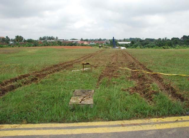
1.17.1 Operator Manuals ................................................................................... 15
                           1.17.1.1 Flight Crew Training Manual (FCTM) 8.3: Non-Normal
                                    Procedure .............................................................................. 15
                           1.17.1.2 Crew Resource Management (CRM) FCTM 1.2 .................. 15
                           1.17.1.3 Hydraulic system FCOM 13.20.1/2/3/4 ................................ 16
              1.1.1       Normal Configuration Landing distance flap 15 and assumed with
                          Medium Reported Braking Action ......................................................... 20
              1.17.2 Quick Reference Handbook QRH 13.2 .................................................. 23
              1.17.3 Non normal Checklist FCT- 737-200 (TM) chapter8.4 April 30,
                     2009 ........................................................................................................ 27
              1.17.4 Thrust Reversers FCOM 7.20.8 ............................................................. 28
    1.18      Additional Information ........................................................................................ 30
              1.18.1 The InterviewStatement Summary ......................................................... 30
              1.18.2 The Flight Attendant recollection........................................................... 31
              1.18.3 The on board Mechanic recollection ...................................................... 31
              1.18.4 The Air Traffic Controllerrecollection ................................................... 31
              1.18.5 The Airport Fire Fighting Crew recollection ......................................... 31
              1.18.6 Laboratory examination of failed component ........................................ 32
    1.19      Useful or Effective Investigation Techniques ..................................................... 32
2   ANALYSIS ..................................................................................................................... 33
    2.1       Loss of hydraulic System A................................................................................. 33
    2.2       Crew Coordination for a Non-NormalSituation .................................................. 34
    2.3       Landing Distance Required With Loss of Hydraulic System A .......................... 35
3   CONCLUSION .............................................................................................................. 38
    3.1       Findings ............................................................................................................... 38
    3.2       Contributing Factors ............................................................................................ 40
4   SAFETY ACTION ........................................................................................................ 41
    PT. Sriwijaya Air ............................................................................................................ 41
5   SAFETY RECOMMENDATIONS ............................................................................. 42

                                                                              ii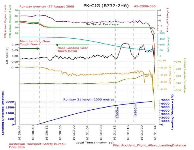
TABLE OF FIGURES
Figure 1: Archive photo of the aircraft ................................................................................... 1
Figure 2: The last aircraft position and condition.................................................................. 3
Figure 3: Showing both engines detached .............................................................................. 4
Figure 4: Weather Chart issued by WAFC on 27 August 2008 ............................................. 7
Figure 6: Normal configuration landing distance ................................................................. 20
Figure 7: Non normal configuration landing distance .......................................................... 21
Figure 8: Table of the Vref in specified weight and flaps setting ........................................ 22
Figure 9: Thrust Reverers Schematic ................................................................................... 29

                                                                         iii
ABBREVIATIONSAND DEFINITIONS
ARFF         :   Airport Rescue and Fire Fighting
ATIS         :   Automatic Terminal Information Services
ATPL         :   Air Transport Pilot License
ATR          :   Avions de Transport Regional
ATS          :   Air Traffic Service
BMKG         :   Badan Meterologi Klimatologi dan Geofisika (Metrological
                 Climatology and Geophysical Agency)
°C           :   Degrees Celsius
CPL          :   Commercial Pilot Licence
CVR          :   Cockpit Voice Recorder
DGCA         :   Directorate general Civil Aviation
EGPWS        :   Enhanced Ground Proximity Warning Systems
FA           :   Flight Attendant
FCOM         :   Flight Crew Operation Manuals
FDR          :   Flight Data Recorder
IAF          :   Initial Approach Fix
ICAO         :   International Civil Aviation Organization
ILS          :   Instrument Landing System
Km           :   Kilometer(s)
mbs          :   Millibars
ND           :   Navigation Display
KNKT/ NTSC   :   Komite Nasional Keselamatan Transportasi/ National Transportation
                 Safety Committee
PF           :   Pilot Flying
PIC          :   Pilot in Command
PM           :   Pilot Monitoring
QNH          :   Height above mean sea level based on local station pressure
S/N          :   Serial Number
SIC          :   Second in Command
UTC          :   Universal Time Coordinate
VOR          :   VHF Omni-directional Range

                                                 iv
INTRODUCTION
SYNOPSIS
On 27 August 2008, a Boeing 737-200 aircraft, registered PK-CJG, was being operated on a
scheduled passenger service from Soekarno-Hatta International Airport, Jakarta to Sultan
Thaha Airport, Jambi with flight number SJY 062. On board on this flight were two pilots,
four flight attendants, and 124 passengers.

The Pilot in Command (PIC) acted as Pilot Flying (PF) while the Second in Command (SIC)
acted as the Pilot Monitoring (PM).

The flight time from Jakarta to Jambi estimated about one hour and the aircraft was
dispatched with approximate for 4 hours of fuel endurance. At 09:18 UTC the SIC contacted
Thaha Tower controller and reported that the aircraft was descending and passing FL160 and
has been cleared by Palembang Approach control to descend to 12,000 feet. The PIC flew the
aircraft direct to intercept the final approach runway 31. While descending through 2500 feet
and about 8 miles from the VOR, the flap one degree and flap 5° were selected. Subsequently
the landing gear extended and flap 15° was selected. 13 seconds after flap 15 selection, the
pilots noticed that the hydraulic system A low pressure warning light illuminated, and also the
hydraulic system A quantity indicator showed zero. The PIC continued the approach and
adived the SIC that he aimed to fly the aircraft slightly below the normal glide path in order to
get more distance available for the landing roll.

The aircraft touched down at 0930 UTC , and during the landing roll the PIC had difficulty to
select the reversers while applying manual braking. The aircraft drifted to the right of the
runway centre line about 200 meters prior went out of the runway, stopped at about 120
meters from the end of the runway 31 on a surface 6 meters below the runway surface. Three
farmers who were working on that area hit by the aircraft and seriously injured.

All crew and passengers safely evacuated the aircraft. No significant property damage was
reported

The SSCVR and SSFDR were good, examined and subsequently downloaded using the ATSB
facilities.

The contributing factors were as the following of:
  •   The Loss of Hydraulic System A occurred requires the pilots to refere the QRH. At the
      time of occurrence, the pilots has sufficient time to do the procedure and determine all
      the consequences prior to land the aircraft. However the pilot did not use the QRH
      which will assist and guide with the detail of procedures and steps to do before decision
      to land was made, therefore the KNKT recommends that the operator shall ensure that
      pilots when facing the non normal situation should use the QRH and other references
      procedures.
  •   Crew Resource Management is the application of team management concepts and the
      effective use of all available resources to operate a flight safely and in addition to the

                                                       v
crew, it includes all other groups routinely working with the aircrew are involved in
      decision required to operate a flight. In fact, there was no discussion concerning to the
      non normal situation as described on the CRM before decision to land was made.
At the time of issuing this final report, the Komite Nasional Keselamatan Transportasi
(KNKT) has received any safety actions taken by the operator following this serious incident.

According to factual information, the findings and the contributing factors, on this final report
the Komite Nasional Keselamatan Transportasi (KNKT) issued several safety
recommendations addressed to PT. Sriwijaya Air and Directorate General of Civil Aviation
(DGCA).

                                                       vi
1 FACTUAL INFORMATION
1.1 History of the Flight
      On 27 August 2008, a Boeing 737-200 aircraft, registered PK-CJG, was being operated
      on a scheduled passenger service from Soekarno-Hatta International Airport, Jakarta to
      Sultan Thaha Airport, Jambi1 with flight number SJY 062. On board the flight were two
      pilots, four flight attendants, and 124 passengers (Figure 1).
      The Pilot in Command (PIC) acted as Pilot Flying (PF) while the Second in Command
      (SIC) acted as Pilot Monitoring (PM).

                                        Figure 1: Archive photo of the aircraft
      The flight time from Jakarta to Jambi was estimated to be about one hour and the
      aircraft was dispatched with approximately 4 hours of fuel endurance. The number one
      electrical engine driven generator was unserviceable, as such the Auxiliary Power Unit
      (APU) generator was used during the flight to maintain two generators operation.
      Prior to descent into Jambi, the PIC conducted the crew briefing and stated a plan for
      makinga straight-in approach to runway 31 with flap 40°, reviewed the go-around
      procedures and stated that Palembang 2 was the alternate airport.There was no
      abnormality recorded nor reported until the PIC commencedthe approach to Jambi.
      At 09:18 UTC, the SIC contacted Thaha Tower controller and reported that the aircraft
      was descending and passing FL160 and had been cleared by Palembang Approach
      control to descend to 12,000 feet. The Thaha Tower controller issued a clearance to
      descend to 2500 feet and advised that runway 31 was in use.. The SIC asked about the
      weather conditions and was informed that the wind was calm, rain over the field and
      low cloud on final approach to runway 31.
      The PIC flew the aircraft direct to intercept the final approach to runway 31. While

1 Sultan Taha Airport, Jambi will be named Jambi for the purposes of this report.
2Sultan   Badarudin Airport, Palembang will be named Palembang for the purposes of this report

                                                                      1
descending through 2500 feet, and about 8 miles from the VOR, the flap one degree and
flap 5° were selected. Subsequently the landing gear was extended and flap 15° was
selected.
13 seconds after flap 15 selection, the pilots noticed that the hydraulic system A low
pressure warning light illuminated, and also the hydraulic system A quantity indicator
showed zero. The PIC commanded the SIC to check the threshold speed for the existing
configuration of landing, weight and with flap 15°. The SIC called out that the threshold
speed was 134 kts and the PIC decided to continue with the landing.
The PIC continued the approach and advised the SIC that he aimed to fly the aircraft
slightly below the normal glide path in order to get more distance available for the
landing roll.
The aircraft touched down at 0930 UTC and during the landing roll, the PIC had
difficulty selecting the thrust reversers. The PIC the applied manual braking. During the
subsequent interview, the crew reported that initially they felt a deceleration then
afterward a gradual loss of deceleration. The PIC reapplied the brakes and exclaimed to
the SIC about the braking condition, then the SIC also applied the brakes to maximum
in responding to the situation.
The aircraft drifted to the right of the runway centre line about 200 meters prior to
departing off the end of the runway, and stopped about 120meters from the end of the
runway 31 in a fieldabout 6meters below the runway level. Three farmers who were
working inthat area were hit by the aircraft. One was fatally injured and the other two
were seriously injured.
The pilots reported that, after the aircraft came to a stop, they executed the Emergency
on GroundProcedure. The PIC could not put both start levers3to the cut-off position,
and also could not pull the engines and APU fire warning levers4. The PIC also noticed
that the speed brake lever did not extend. The radio communications and the interphone
were also not working.
The flight attendants noticed a significant impact before the aircraft stopped. They
waited for any emergency command from the PIC before ordering the evacuation.
However, the passengers started to evacuate the aircraft through the right over-wing exit
window before commanded by the flight attendants. The flight attendants subsequently
executed the evacuation procedure without command from the PIC.
The left aft cabin door was blocked by the left main landing gear that had detached from
the aircraft andthe flight attendants were unable to open the door. The right main
landing gear and both engines were also detached from the aircraft (Figures 3).
The Airport Rescue and Fire Fighting (ARFF) come to the crash site and activated the

   3   Start levers, are levers in the cockpit to open or close the fuel supply to the engine. To open the levers are in
        idle position and to close are in cut-off position.
  4   Engine and APU warning switches are the levers to stop the fuel and hydraulic supply to the engines and APU.
       These levers are operates in an emergency condition only.

                                                                   2
extinguishing agent while the passengers were evacuating the aircraft. The PIC, SIC and
FA1 were the last persons to evacuat the aircraft.
The APU was still running after all passengers and crew evacuation completed,
afterward one company engineer went to the cockpit and switched off the APU.
All crew and passengers safely evacuated the aircraft. No significant property damage
was reported.
Figure 2: The last aircraft position and condition
1.2 Injuries to Persons
Total in
Injuries Flight crew Passengers Others
Aircraft
Fatal - - - 1
Serious 2 10 12 2
Minor/None 4 114 118 -
TOTAL 6 124 130 3
1.3 Damage to Aircraft
The aircraft was substantially damaged. Both engines had detached from the pylons, and
the left main landing gear had separated and blocked the left rear door. The nose
raddome and the nose landing gear also detached.
3Right engine
Left engine
Figure 3: Showing both engines detached
1.4 Other Damage
No significant damage reported.
1.5 Personnel Information
1.5.1 Pilot in Command
Gender : Male
Date of birth : 36 years old
Marital status : Married
Nationality : Indonesia
License : Air Transport Pilot License (ATPL)
Valid to : 20 October 2004
Aircraft type rating : B737-200
Medical certificate : First class
Last of medical : 24 June 2008
Validity : 24 December 2008
Medical limitation : None
Last line check : 28 April 2008
Last proficiency check : 09 March 2008
Flying experience
Total hours : 7,794 hours 07 minutes
Total on this type : 6,238 hours 07 minutes
Last 90 days : 233 hours 30 minutes
Last 60 days : 125 hours
Last 24 hours : 02 hours 49 minutes
This flight : 01 hour 15 minutes
41.5.2 Second in Command
Gender : Male
Date of birth : 34 years old
Marital status : Indonesia
Nationality : Married
License : CPL
Validity : 25 March 2008
Aircraft type rating : B737-200
Medical certificate : First Class
Last of medical : 26 March 2008
Validity : 26 September 2008
Medical limitation : None
Last line check : 22 September 2007
Last proficiency check : 15 March 2008
Flying experience
Total hours : 5,254 hours
Total on this type : 4,143 hours
Last 90 days : 275 hours 50 minutes
Last 60 days : 181 hours 40 minutes
Last 24 hours : 02 hours 49 minutes
This flight : 01 hour 15 minutes
1.6 Aircraft Information
1.6.1 General
Registration Mark : PK-CJG
Manufacturer : Boeing Company
Country of Manufacturer : United States of America
Type/ Model : Boeing 737-200
Serial Number : 23320
Date of manufacture : 1985
Certificate of Airworthiness
Issued : 11 August 2008
Validity : 10 August 2009
5Category : Transport
Limitation : None
Certificate of Registration
Number : 2124
Issued : 03 May 2008
Validity : 02 May 2009
Time Since New : 49,996.53 hours
Cycles Since New : 54,687 cycles
Last major inspection : 47,963.06 Flight Hours/ November 2007
Last minor check : -
1.6.2 Engines
Manufacturer : Pratt and Whitney, Canada
Type/Model : JT8D-9A
Serial Number-1 engine : P707317B
Time Since New : 34,718.06 hours
Cycles Since New : 35,956 cycles
Serial Number-2 engine : P687755B
Time Since New : 42,690.37 hours
Cycles Since New : 46,254 Cycles
1.6.3 Weight and Balance
The aircraft departed from Jakarta within the weight and balance envelope and the
load specifications were as follows:
Takeoff weight : 106,095 lbs (Maximum 111,521 lbs)
Takeoff fuel : 18,600 lbs
Trip fuel : 6,521 lbs
Landing Weight : 99,574 lbs (maximum 105,000 lbs)
61.7 Meteorological Information
The weather forecast issued by World Area Forecast Centre (WAFC) London that
was valid for FL 250 - 630 on 27 August 2008. The red circle shows that there was
significant cloud formation over Jambi (Figure 4).
Figure 4: Weather Chart issued by WAFC on 27 August 2008
The METAR issued by the Sultan Thaha Meteorology Office Jambi at 09:12 UTC:
Surface wind 300/04
Visibility 8 Km
Present weather continuous rain
Clouds Few CB 1000; BKN 1000
Temperature / dew point 25° C /24° C
QNH / QFE 1008 /1005
1.8 Aids to Navigation
There were two non-precision approaches provided by Sultan Thaha airport of Jambi
which were used for both runways 31 and 13. The navigation aids consisted of Very
High Frequency Omnidirectional Radio Range (VOR) combined with Distance
Measuring Equipment (DME) on a frequency of 117.5 MHz, and the Non-Directional
Beacon (NDB) on frequency 365 KHz. Other facilities such as, Approach Light System
(ALS), Precision Approach Path Indicator (PAPI) lights and runway lights were
available.
During the day of the occurrence all the navigation aids and facilities were operating
7normally and considered not related to the accident.
1.9 Communications
The communications between air traffic services and the pilots were recorded by
ground-based automatic voice recording equipment and the cockpit voice recorder
(CVR) for the duration of the flight. The quality of the voice recording was good.
1.10 Aerodrome Information
1.10.1 Refer to Aeronautical Information Publication (AIP) published by DGCA:
Airport Name : Sultan Thaha
Airport Identification : WIPA/ DJB
Airport Operator : PT. AngkasaPura II (Persero)
Coordinate : 01° 38’ 08” S; 103° 38’ 35” E
Elevation : 88 feet
Runway Direction : 13-31
Runway Length : 7283 feet/ 2220 meter
Runway Width : 30 m
Surface : Asphalt
RESA : 31 90 x 90 m, available on runway
1.10.2 The Airport Rescue and Fire Fighting facilities
The airport Rescue and Fire Fighting (ARFF) facilities was category VI, equipped
with 4 crash car units, 2 rescue car units, 1 command car unit, 2 ambulance units and
23 trained personnel. The rescue and firefighting equipment was not suitable to
remove the wreckage.
1.11 Flight Recorders
The aircraft was equipped with Solid State Digital Flight Data Recorder (SSFDR) and
Solid State Cockpit Voice Recorder(SSCVR). Both recorders were recovered from the
accident site and transported to NTSC head office.
In accordance with clause 5.23 of Annex 13 to the Convention on International Civil
Aviation, the KNKT requested assistance from the Australian Transport Safety Bureau
(ATSB) in the recovery and analysis of information from the Solid State Digital Flight
Data Recorder (SSFDR) and Solid State Cockpit Voice Recorder (SSCVR).
The SSCVR and SSFDR were examined and subsequently downloaded using the ATSB
facilities.
The SSFDR was downloaded and found to contain more than 68 flights including the
8accident flight. Examination of the SSFDR found that the aircraft landed on runway 31
at an indicated air speedof 165 knots.
During the landing roll, the aircraft drifted right of the runway centreline. The SSFDR
and SSCVR data ceased as the aircraft stopped (Figure 5).
1.11.1 SSFDR Specification
Manufacturer : Fairchild
Model : F1000
P/N : S603-1000-00
S/N : 00326
ARINC : 5424
Specific events and systems recorded by SSDFR
Speed at touchdown
Aircraft altitude
Roll angle
Figure 5: FDR data graph from aircraft altitude 500 feet until end of recording
9The FDR graph shows that, when the aircraft was 550 feet, the aircraft speed was 171
kts and slight rolled to the left and right in average to 4°.At touch down the aircraft
speed was 165 kts (Figure 6).
The point of aircraft stopped
since touch down
Figure 6: The FDR data graph indicated the distance from touchdown to stop
The graph shows that after the aircraft main and nose landing gear touched down, there
was no reverse thrust, the heading remained relatively steady on 310° and then changed
to approximately 320° after the aircraft rolled 1660 meters and then stopped at 2020
meters which was the end of the recording.
1.11.2 CVR Specification
Manufacturer : Fairchild
Model : A100
P/N : 93-A100-30
S/N : 50980
Level : 18
Date : 12/85
The aircraft was equipped with a Solid State Cockpit Voice Recorder (SSCVR) with 30
minutes recording time.
The SSCVR was downloaded and found to contain about thirty‐two minutes of data
from the accident flight on four channels including an Area Microphone channel. The
audio downloaded from the CVR was provided to KNKT investigators for further
analysis.
10A translation of the cockpit audio from SSCVR was prepared by the KNKT at the
ATSB facility. The investigation combined the SSFDR and SSCVR significant events
in the transcript for analysis purposes.
Altitude IAS(kn Heading
Time Event
(feet) ots) (deg)
9:18:09 Pilot first contact with Thaha Tower controller and
was informed that wind calm, rain over the field and
low cloud on final runway 31.
9:19:05 14243 278 336 Pilot and Co-pilot discuss 'go-around' at Jambi
airport and whether there is any difficulties doing
that at Jambi airport,pilot suggested landed at
Palembang airport.
9:20:32 11510 258 336 Pilot asked concerning the MDA, minimum
visibility, approach go around procedure.
9:26:19 2797 202 319 Altitude alert
9:26:31 Flaps one
9:27:31 1911 176 326 The pilot reported runway insight.
9:27:33 1894 176 326 Clear to land
9:28:06 Landing gear down and flap selected to 15°.
9:28:35 1638 169 319 "Flight attendant landingposition..."
9:28:39 Pilot noticed hydraulic problem
9:28:45 1573 165 318 The PIC confirming the hydraulic quantity that was
empty.
9:28:54 1551 159 317 The PIC decided to continue landing and asked the
approach speed for flap 15.
9:29:55 The SIC informed that the approach speed for
existing condition was 134 kts.
9:29:59 582 171 311 "Don't sink.." (five times)
9:30:06 The PIC intended to fly slightly below glide.
9:30:52 66 165 309 Touch down
9:30:54 81 164 310 "No reverse ...no reverse... pullout parking
brake...brake ....pull out ...!!!"and hard collision sound
9:30:57 89 160 310 Nose landing gear touchdown
9:30:58 The PIC exclaimed that brake only once and no
reverse
9:31:06 The PIC asked the SIC to assist the braking.
9:31:19 91 59 319 Sounds similar to impact
9:31:23 -246 58 323 End of CVR data
Table 1: Sequence of events developed from recorded SSFDR and SSCVR data
111.12 Wreckage and Impact Information
An examination of the accident site including the cockpit area found that, the standby
compas showed 330°, the speed brake lever was forward (stowed position), the flaps
position handle at 15 and thrust reverser levers stowed.
The aircraft examination showed that the spoilers were stowed in the flush position,
leading edge slats deployed, both overwing emergency windows opened and evacuation
doors opened, except the left rear door that was blocked by the left main landing gear.
The escape slide of the aft right door was not deployed.
Wheel marks were found at about 200 meters before the runway end and continued 120
meters past the Runway End Safety Area (RESA) until the aircraft came to rest (Figures
7 to 9).
Other information is displayed in the figure below:
Brake & Hydraulic
pressure indicators
Autobrake selector
Flaps/ Landing
inhibit switch
Figure 7: Hydraulic system indicator and auto brake selector
The yellow boxes in Figure 7 shows the Auto brakes off, flap/ landing gear inhibit guard
switch opened and brake pressure and hydraulic pressure system B on green band while
on system A loss.
12Right Main wheel marks on taxi way to apron
Figure 8: Main wheel marks on the taxiway to apron
Figure 9: Wheel marks on the RESA runway 31
131.13 Medical and Pathological Information
No medical or pathological investigations were conducted as a result of this accident,
nor were they required.
1.14 Fire
There was no fire.
1.15 Survival Aspects
The Airport Rescue and Fire Fighting (ARFF) arrived at the crash site during the
passenger evacuation and sprayed extinguisher agent to the tail section of the aircraft at
09:38 UTC.
Figure 5: Shows during and after the ARFF operation
1.16 Tests and Research
There was no test and research conducted at this investigation.
1.17 Organizational and Management Information
Aircraft Operator : PT. Sriwijaya Air
Address : Jl. PangeranJayakarta No. 68C
Certificates Number : AOC /121-035
Operator Designator : SJY
The operator structure of organization was in accordance with CASR 121 and specified
in the AOC/OPSPEC. Sriwijaya Air operated several B737- 200 and B737 300/400 and
served domestic and international routes specified in the route approvals.
For the aircraft maintenance, Sriwijaya Air had an agreement with Aero Nusantara
Indonesia (ANI) who held the Aircraft Maintenance Organization (AMO) 145 issued by
the Directorate General of Civil Aviation (DGCA).
The company manuals stated that the pilot proficiency and training including Crew
Resources Management (CRM) recurrent training performed for all flight crew atits due
time. Refer to the information from the operator management the initial CRM, and
recurrent trainings conducted by the third parties.
The Flight Crew Training Manual (FCTM) described the details of crew coordination
for a non-normal situation including pilot decision making, which contains information
that the pilot in command has the authority and responsibility for the safety of the flight.
14The Flight Crew Operation Manual (FCOM) described the detailed aircraft system and
operation performance including the normal and non-normal landing distance with
hydraulic system failures with specified aircraft weight and flaps setting.
During the type rating training the pilots have been trained for hydraulic system failure
included loss of system A, loss of system B and loss of both hydraulic systems (manual
reversion).
1.17.1 Operator Manuals
1.17.1.1 Flight Crew Training Manual (FCTM) 8.3: Non-Normal Procedure
Approach and Landing
When a non-normal situation occurs, a rushed approach can often complicate the
situation. Unless circumstances require an immediate landing, complete all corrective
actions before beginning the fmal approach.
For some non-normal situations, the possibility of higher airspeed on approach,
longer landing distance, a different flare profile or a different landing technique
should be considered.
Plan an extended straight-in approach with time allocated for the completion of any
lengthy NNC steps such as the use of alternate flap or landing gear extension
systems. Arm autobrakes (as installed) and speedbrakes unless precluded by the
NNC.
Note: The use of autobrakes (as installed) is recommended because maximum
autobraking may be more effective than maximum manual braking due to timely
application upon touchdown and symmetrical braking. However, the Advisory
Information in the PI chapter of the FCOM provides Non-Normal
Configuration Landing Distance data based on the use of maximum manual
braking. When used properly, maximum manual braking provides the shortest
stopping distance.
Fly a normal glide path and attempt to land in the normal touchdown zone. After
landing, use available deceleration measures to bring the airplane to a complete stop
on the runway. The captain must determine if an immediate evacuation should be
accomplished or if the airplane can be safely taxied off the runway.
1.17.1.2 Crew Resource Management (CRM) FCTM 1.2
Crew resource management is the application of team management concepts and the
effective use of all available resources to operate a flight safely. In addition to the
aircrew, it includes all other groups routinely working with the aircrew who are
involved in decisions required to operate a flight. These groups include, but are not
limited to, aircraft dispatchers, flight attendants, maintenance personnel, and air
traffic controllers.
Throughout this manual, techniques that help build good CRM habit patterns on the
flight deck are discussed. For example, situational awareness and communications
are stressed. Situational awareness, or the ability to accurately perceive what is going
on in the flight deck and outside the aircraft, requires on going questioning,
15crosschecking, communication, and refinement of perception.
It is important that all flight deck crewmembers identify and communicate any
situation that appears unsafe or out of the ordinary. Experience has proven that the most
effective way to maintain safety of flight and resolve these situations is to combine the
skills and experience of all crewmembers in the decision making process to determine
the safest course of action.
1.17.1.3 Hydraulic system FCOM 13.20.1/2/3/4
Introduction
The airplane has three hydraulic systems: A, B and standby. The standby system is
used if system A and/or B pressure is lost. The hydraulic systems power the following
airplane systems:
• flight controls • nose wheel steering
• leading edge flaps and slats • thrust reversers
• trailing edge flaps • yaw damper
• spoilers • autopilots
• landing gear • cargo door (cargo airplanes
• wheel brakes only)
16Each hydraulic system has a fluid reservoir located in the main wheel well area. The
reservoirs are pressurized by engine bleed air directed into the system A reservoir.
Fluid balance lines interconnect all reservoirs. Pressurization of all reservoirs ensures
positive fluid supply to all hydraulic pumps and controls the fluid level in the reservoirs.
The ground interconnect valve allows system B to pressurize system A for systems check
when the airplane is on the ground, the parking brake is set and electrical power is
available.
Hydraulic System A
System A pressure is provided by an engine driven pump on each engine. The ENG 1 and
ENG 2 pump ON/OFF switch controls the engine–driven pump output pressure.
Positioning the switch to OFF isolates fluid flow from the system components. However,
the engine–driven pump continues to rotate as long as the engine is operating. Pulling the
engine fire switch shuts off the fluid flow to the engine–driven pump and deactivates the
related LOW PRESSURE light.
Hydraulic fluid used for cooling and lubrication of the pumps passes through a heat
exchanger before returning to the reservoir. The heat exchanger is located in main fuel
tank No. 1 and must be covered with fuel for operation of the pumps.
Pressure switches, located in the pump output lines, send signals to illuminate the related
LOW PRESSURE light if pump output pressure is low. A check valve, located in each
output line, isolates each pump from the system. The A system pressure transmitter sends
the combined pressure of the pumps to the A HYDRAULIC SYSTEM PRESSURE
indicator needle.
Hydraulic System B
System B pressure is provided by two electrically driven hydraulic pumps. The ELEC 1
or ELEC 2 pump ON/OFF switch controls the related electric motors.
17The system B reservoir is connected to the system A reservoir and the standby reservoir
through balance lines for single point pressurization and servicing. The B LOW
QUANTITY light illuminates when reservoir fluid is low.
Hydraulic fluid used for cooling and lubrication of the pumps passes through a heat
exchanger before returning to the reservoir. The heat exchanger for system B is in main
fuel tank No. 2. If a pump or the fluid becomes overheated, the OVERHEAT light
illuminates.
CAUTION: Minimum fuel for ground operation of electric pumps is 760 Kgs
(1675 Lbs) in fuel tank No. 2.
Pressure switches, located in the pump output lines, send signals to illuminate the related
LOW PRESSURE light if pump output pressure is low. Check valves isolate the two
pumps. The system pressure transmitter sends the combined pressure of the electric
motor–driven pumps to the B HYDRAULIC SYSTEM PRESSURE indicator needle.
The automatic load shedding feature deactivates the respective system B hydraulic
pump when a generator is lost. The LOW PRESSURE light illuminates and the pump
switch remains in the on position. When the bus is powered again, the pump is activated
and the LOW PRESSURE light extinguishes.
Standby Hydraulic System
The standby hydraulic system is provided as a backup if system A and/or B pressure is
lost. The standby system reservoir is connected to the System B reservoir through a
balance line for pressurization and servicing. The standby system LOW QUANTITY light
is always armed and indicates low quantity in the standby reservoir. The LOW PRESSURE
light is armed only when standby pump operation has been selected. The standby system
uses a single electric motor–driven pump to power:
• thrust reversers
• rudder
• leading edge flaps and slats (extend only)
System Operation
Positioning either FLT CONTROL switch to STBY RUD:
• activates the standby electric motor–driven pump
• shuts off the related hydraulic system pressure to ailerons, elevators and rudder
by closing the flight control shutoff valve
• opens the standby rudder shutoff valve
• deactivates the related flight control LOW PRESSURE light when the standby
rudder shutoff valve opens
• allows the standby system to power the rudder.
• (after RSEP modification) illuminates the STBY RUD ON, Master Caution, and
Flight Controls (FLT CONT) lights.
Positioning the ALTERNATE FLAPS master switch to ARM (see the Flight Controls
chapter for a more complete explanation):
18• activates the standby electric motor–driven pump
• arms the ALTERNATE FLAPS position switch
• allows the standby system to power the leading edge flaps and slats and thrust
reversers.
With the loss of System A the standby system will provide pressure to operate the thrust
reversers.
Automatic Operation (after RSEP modification)
Automatic operation is initiated when the following conditions exist:
• FLT CONTROLS switch A is not in the STBY RUD position,
• FLT CONTROLS switch B is in the ON position,
• ALTERNATE FLAPS arming switch is in the OFF position
• the main PCU Force Fight Monitor (FFM) trips.
191.1.1 Normal Configuration Landing distance flap 15 and assumed with Medium
Reported Braking Action
Figure 6: Normal configuration landing distance
The red box shows the distances adjustment for specified condition landing with flaps
15°. The Vref adjustment above 10 kts is 350 feet and if no reversers added by 2260
feet.
20Figure 7: Non normal configuration landing distance
The red boxes shows the distances adjustment for specified condition of hydraulic loss
on system A with flaps 15°. The Vref adjustment above 10 kts is 400 feet. Refers to
normal landing distance table, if no reversers the landing distance added by 2260 feet.
21Figure 8: Table of the Vref in specified weight and flaps setting
The above table shows the Vref of 138 kts for the aircraft landing weight 100,000 lbs
with flap 15 (red boxes).
Refer to landing distance as stated FCOM chapter PI.12.1 normal and PI 12.9non
normal and no reversers with reference of Vref 138 kts were summarized as the
following table:
Adjustment of Non normal hydraulic
Normal flaps 15°
loss of system A
flaps15°
(feet)
(feet)
Landing weight 4630 4950
100,000 lbs
Elevation 14 26
Wind (tail/ head) 0 0
Temperature 25 C 300 300
Vref 138 kts 0 0
No reverse 2260 0
Total 7204 5276
The table shows with the Loss of Hydraulic System A, with the existing aircraft weight
and conditions at the time of occurrence the landing distance will be 5276 feet.
.
221.17.2 Quick Reference Handbook QRH 13.2
2324
25
26
1.17.3 Non normal Checklist FCT- 737-200 (TM) chapter8.4 April 30, 2009

      A suitable airport is defined by the operating authority for the operator based on
      guidance material, but in general must have adequate facilities and meet certain
      minimum weather and field conditions. If required to divert to the nearest suitable
      airport (twin engine airplane with an engine failure), the guidance material also
      typically specifies that the pilot should select the nearest suitable airport "in point of
      time" or "in terms of time." In selecting the nearest suitable airport, the pilot-in-
      command should consider the suitability of nearby airports in terms of facilities and
      weather and their proximity to the airplane position. The pilot-in-command
      may determine, based on the nature of the situation and an examination of the
      relevant factors, that the safest course of action is to divert to a more distant airport
      than the nearest airport. For example, there is not necessarily a requirement to spiral
      down to the airport nearest the airplane's present position if, in the judgment of the
      pilot-in-command, it would require equal or less time to continue to another nearby
      airport.

                                                    27
For persistent smoke or a fire which cannot positively be confirmed to be completely
extinguished, the safest course of action typically requires the earliest possible descent,
landing and evacuation. This may dictate landing at the nearest airport appropriate
for the airplane type, rather than at the nearest suitable airport normally used for the
route segment where the incident occurs.
Air Systems
Cabin Altitude Warning
There have been several reports of cabin altitude warning alerts caused by improperly
configured engine bleed air and air conditioning pack switches. This condition is often
the result of crews failing to reconfigure switches following a no engine bleed takeoff.
Additionally, there have been reports of crews delaying their response to the cabin
altitude warning alert because it was confused with the takeoff configuration warning
horn.
In order to address the problem of incorrectly positioning switches that affect
pressurization, the normal takeoff procedure has been modified to direct the crew to
set or verify the correct position of the engine bleed air and air conditioning pack
switches after flap retraction is complete. Engine bleeds and air conditioning packs have
also been included as specific items in the After Takeoff normal checklist. Additionally,
when doing a no engine bleed takeoff, reference to the No Engine Bleed Takeoff
supplementary procedure, in conjunction with good crew coordination, reduces the
possibility of crew errors.
1.17.4 Thrust Reversers FCOM 7.20.8
Reverse thrust is accomplished by two doors which block engine exhaust and deflect
the exhaust flow forward. The doors operate by system A hydraulic pressure through
the gear down hydraulic line. Alternate operation at a reduced rate is available with
the standby hydraulic system (the reverser may not stow). A REVERSER UNLOCKED
light located on the center instrument panel will illuminate when either thrust reverse
door is not in the stowed and locked position.
With the engine fire warning switch down and the engine low oil pressure switch sensing
pressure, an electrical circuit including the nose gear, or main gear air/ground safety
sensors, allows the thrust reversers to deploy. When all three electrical conditions are
satisfied, the isolation valve will be solenoid-held to the open position. Loss of any
electrical condition will cause the isolation valve to spring closed. The selector valve
is controlled by the reverse thrust lever and directs hydraulic pressure to unlock,
extend,retract or lock the doors.
The amber ISOLATION VALVE light will illuminate whenever a comparator senses
a disagreement between the electrical condition to either isolation valve and the
hydraulic pressure condition (the isolation valve open in flight, or closed on the
ground). Positioning the guarded switch to the OVERRIDE position bypasses the oil
pressure switch and the air/ground safety sensor and opens the isolation valve (if the
fire switch is down). The override switches should not be used by flight crews for
normal operations in flight or on the ground.
28An engine control/reverser interlock system is provided. This interlock limits the
thrust increase command if the reverser remains stowed when the reverse thrust lever
is moved to a reverse position. The interlock is withdrawn during reverser translation
from the stowed position to the deployed position. If the reverser
remains deployed when the reverse thrust lever is moved to the forward thrust
position, thrust increase commanded by the forward thrust lever is limited. The
interlock is withdrawn during reverser translation from the deployed position to the
stowed (flight) position. Freedom of motion of the forward thrust levers is not an
absolute indication that the thrust reverser is fully deployed or stowed and locked,
since the interlocks are withdrawn during reverser motion.
WARNING: Actuation of the thrust reversers on the ground without suitable
precautions is dangerous to ground personnel.
Figure 9: Thrust Reverers Schematic
The thrust reverser schematicon figure 11 shows that with the engine fire warning
switch down and the engine low oil pressure switch sensing pressure, an electrical
29circuit including the nose gear, or main gear air/ground safety sensors (the three green
circles). If all three electrical conditions aresatisfied,the solenoid will be held in the
open position(red circle) and allowing the thrust reversers to deploy.
1.18 Additional Information
1.18.1 The InterviewStatement Summary
The Pilots recollection
During final approach (visual approach) to runway 31 at Sultan Thaha airport –
Jambi (WIPA), a B737-200 flight SJY 062, shortly after the landing gears were down
and flaps 15° degrees configuration, the crew selected the flaps to 25 degrees, the
crew noticed the the low pressure light of hydraulic system illuminated.
According to the pilot,the aircraft position was about 8 Nm from the VOR while
descending passing 2500 feet to 2000 feet (2000 feet was their requested altitude to
the ATC).
The captain (PF) and the first officer (PM) also confirmed that the low pressure
condition was also indicated by low pressure indication of system A hydraulic
pressure indicator. The captain also stated the hydraulic brake pressure on the
indicator was at the green band.
The captain ordered first officer to carry-out QRH. The first officer stated that he
preferred the captain to make go-around in order to properly carry out the QRH, but
not verbally stated, whereas the captain decided to continue approach with the
existing configuration of flaps 15 degrees reasoning that the existing aircraft weight
(approx. 90,000 lbs) and flaps 15 configurations landing distance was not exceeded
the available runway length.
The first officer continued to complete the QRH, but he stated that he was not sure
whether he did the correct QRH actions. The captain also stated that he did not verify
the first officer action of the QRH.
The captain stated, he flew the approach of “duck-under” method (below glide path)
as he believed this method would achieve the shortest distance result when the
aircraft touchdown well before normal touchdown zone.
Both flight crew stated the touchdown was smooth, the captain stated that after
touchdown when he tried to apply reverser, and he could not be able to raise the
thrust lever reverser because it felt very heavy. The captain then applied the brake
manually with one steady full application. Both pilots stated that the aircraft was
initially decelerated but afterward lost its deceleration. The captain stated that he
reapplied the brake and exclaimed to the first officer about the braking condition.
The first officer stated that he also pressed the brake pedals to maximum deflection
in responding to the situation. Both pilots stated that the aircraft unable to decelerate
and stopped within the runway and the overrun was very likely.
The aircraft drifted to the right of the runway about 200 meters before end of
runway. The final position of the aircraft rested at coordinate 01˚ 37’ 52.56” S 103˚
38’ 12.84 E, elevation 104 feet. Compass heading reading of 033 degrees. The
aircraft was substantially damaged (both engine are detached from the pylons. left
30main landing gear was detached from its position and ”stacked” with in-board flaps
and engine number 1 blocking the left rear door, nose landing gear was detached,
front section of the fuselage was structurally collapsed; especially on its upper
structure, right main gear was still on its position below the right wing;however the
cockpit and cabin generally intact; its floor relatively level and doors (except left
hand rear door) was in good shape and operational.
The captain later added that after the aircraft stopped, he noticed that the speed
brakes lever had never extended. He also stated that he performed Passenger
Evacuation drill items, he could not put both start levers to cut-off, and he was also
unable to pull the engine and APU fire switches. Both pilots stated that their radio
communication and interphone did not work as well.
1.18.2 The Flight Attendant recollection
All flight attendant stated that the touchdown was very smooth which worried them
as they knew that airport does not have quite long runway. They also stated that no
sound of engine reverser was heard after touchdown as normally they heard. They
also stated that they felt initially a marked deceleration but then suddenly loss the
deceleration. The forward flight attendants stated that before touchdown they heard a
machine voice from GPWS activated but could not identify what kind of voice. The
forward flight attendant also stated that during the landing rollout after the aircraft
loss its initial deceleration, they heard the captain yelling about the brake condition.
1.18.3 The on board Mechanic recollection
The mechanic onboard stated that the touchdown was very smooth, he also remarked
that he did not hear engine reverser noise as he usually expected during landing
rollout. He also stated that initially the aircraft decelerate positively but suddenly it
accelerated as it loss its deceleration. He was seated in row number 5C.
1.18.4 The Air Traffic Controllerrecollection
The SJY 062 at 09:25.45 UTC reported that the position was 14 Nm from the VOR
passing 3000 feet and requested to descend to 2000 feet. At 09:26.56 UTC, SJY 062
reported that they have runway insight so the ATC to continue the approach. At
09:27.39 UTC, the ATC stated that the SJY 062 aircraft was visually insight and then
the landing clearance was given. According to the ATC, the crew of SJY 062 read
back the landing clearance as well as details of their aircraft registration. The landing
and rollout decribed by the ATC on duty was normal, when the aircraft passed the
VASIS runway 13 at 09:31.17UTC, the ATC on duty gave landing time and taxi
clearance to apron. The ATC on duty stated that after that landing time and taxi
clearance no response was received from the SJY 062. Afterward, the ATC on duty
stated that after noticing that the aircraft did not slow down an appeared to overrun
then they activated emergency alarm.
1.18.5 The Airport Fire Fighting Crew recollection
During the passenger evacuation as well as the crew left the airplane, the APU was
still running. They asked the engineer of other airline based in Jambi to shut down
the APU from the cockpit. The engineer of other airline stated that he did shutdown
31the APU was witnessed by the airport securities.
The mechanic on board SJY 062, later added that after he evacuated from the aircraft,
he decided to return to the aircraft, went into the cockpit and switched off the battery.
1.18.6 Laboratory examination of failed component
No components were examined in the laboratory.
1.19 Useful or Effective Investigation Techniques
The investigation was conducted in accordance with the KNKT approved policies and
procedures, and in accordance with the standards and recommended practices of Annex
13 to the Chicago Convention.
322 ANALYSIS
The analysis will discuss the relevant safety issues resulting from the investigation to the
runway excursion involving a Boeing 737-200 on 27 August 2008, registered PK-CJG.
For the purpose of analysis the parts of the FCTM of Non Normal operation FCT 737-
200 (TM) 8.3, CRM 1.2 and FCOM on Hydraulic system 13.20.1/2/3/4 were summarized
to identify the relevant systems, procedures and consequences prior to the decision to
land was made by the pilots.
The investigation determined that, prior to the occurrence, the aircraft experienced aloss
of hydraulic system A after the flaps were extended to 15°and the landing gear selected
down. The analysis will therefore discuss issues relating to the following:
1. Loss of Hydraulic System A.
2. Non-Normal flight crew Coordination.
3. Landing Distance required with loss of hydraulic system A.
2.1 Loss of hydraulic System A
The hydraulic system A failure during the approach affected a number of aircraft
systems required for aircraft deceleration during the landing phase.These systems
includes brakes,spoilers,speed brake,flaps and engine thrust reversers.
According to the FCOM, LOSS OF SYSTEM A the following conditions occur:
• Inboard flight spoilers inoperative - Roll rate and speed brake effectiveness
may be reduced in flight.
• Trailing edge flaps normal hydraulic system inoperative - the trailing edge
flaps can be operated with the alternate electric-driven system. Alternate flap
extension time to flaps 15 is approximately 2 minutes.
• Leading edge flaps and slats normal hydraulic system inoperative - The leading
edge flaps and slats can be extended with standby hydraulic pressure. Once
extended, they cannot be retracted.
• Normal landing gear extension and retraction inoperative - Manual gear
extension is needed.
• Ground spoilers inoperative.
• Both thrust reverser normal pressure inoperative - the thrust reversers could be
deployed and retracted at a slower rate.
• Inboard brakes normal hydraulic system inoperative. - Inboard brakes have
accumulator pressure only.
• Nose wheel steering inoperative.
33In addition, other information described in the QRH page 13.3 loss of hydraulic system
Astates as follows:
• The landing gear configuration warning may sound if the flaps are between 10
and 15 and the landing gears are retracted.
• Maximum airspeed is limited to 210 knots.
• The LE FLAPS TRANSIT (Leading Edge Flaps Transit) light will stay
illuminated until the flaps approach the flaps 10 position.
The investigation could not determine the cause of the Hydraulic system A failure due
to the subsequent components and system damage as a result of the accident. However,
irrespectiveof the particular hydraulic system A failure, the procedures and the
consequences arising were described in the specified chapter of FCTM, FCOM and
QRH issued by the aircraft manufacturer.
2.2 Crew Coordination for a Non-Normal Situation
According to the FCTM of Non Normal operation FCT 737-200 (TM) 8.3 When a non-
normal situation occurs, a rushed approach can often complicate the situation. Unless
circumstances require an immediate landing, all corrective actions should be completed
before beginning the final approach.
Furthermore, for some non-normal situations, the possibility of higher speed on
approach, longer landing distance, a different flare profile or different landing technique
should be considered. Therefore, planning an extended straight-in approach with time
allocated for the completion of any non-normal checklist (NNC) steps such the use of
alternate flaps or landing gear extension system.
The Quick Reference Handbook assists flight crew in the decision making process by
indicating those situations where “nearest suitable airport” is required. These situations
are described in the checklist instruction or individual non-normal checklist. In all cases,
the PIC is expected to take the safest course of action.
During this flight, when at 08:28 UTC the flaps was at 15° and the landing gears
extended by the pilot, the hydraulic system A low pressure light illuminated and the
SSFDR recorded that the aircraft altitude was 1800 feet. A short discussion and
verification from the PIC to the SIC concerning to the hydraulic failure were recorded
by the SSCVR, and the PIC decided to continue the approach with the existing aircraft
configuration for runway 31.
The SSCVR did not record any detail of pilots conversation in respect to the abnormal
procedure associated to that particular hydraulic system A failure, either to the flight
attendant or the air traffic controller. Apart from the approach briefing, there was no
discussion in regard to consideration of conducting a missed approach (go-around) once
the hydraulic system failure became apparent.
At the time when the hydraulic system A pressure loss followed by the illumination of
the warning light, the remaining fuel endurance was approximately 2 hours. With such
remaining time the pilots had more than one hour to conduct a missed approach, review
the QRH procedure and explore the risks and consequences prior to making a decision
34You can also read