High precision modulation of a safety critical cyber physical system : control synthesis and experimental validation
←
→
Page content transcription
If your browser does not render page correctly, please read the page content below
This document is downloaded from DR‑NTU (https://dr.ntu.edu.sg)
 Nanyang Technological University, Singapore.

High‑precision modulation of a safety‑critical
cyber‑physical system : control synthesis and
experimental validation

Li, Yutong; Lv, Chen; Zhang, Junzhi; Zhang, Yun; Ma, Wanjing

2018

Li, Y., Lv, C., Zhang, J., Zhang, Y., & Ma, W. (2018). High‑precision modulation of a
safety‑critical cyber‑physical system : control synthesis and experimental validation.
IEEE/ASME Transactions on Mechatronics, 23(6), 2599‑2608.
doi:10.1109/TMECH.2018.2833542

https://hdl.handle.net/10356/84299

https://doi.org/10.1109/TMECH.2018.2833542

© 2018 Institute of Electrical and Electronics Engineers (IEEE). All rights reserved. This
paper was published in IEEE/ASME Transactions on Mechatronics and is made available
with permission of Institute of Electrical and Electronics Engineers (IEEE).

Downloaded on 18 Jul 2024 04:25:19 SGT
> REPLACE THIS LINE WITH YOUR PAPER IDENTIFICATION NUMBER (DOUBLE-CLICK HERE TO EDIT) <                                                      1

          High-Precision Modulation of A Safety-Critical
          Cyber-Physical System: Control Synthesis and
                     Experimental Validation
           Yutong Li, Member, IEEE, Chen Lv, Member, IEEE, Junzhi Zhang, Yun Zhang, Wanjing Ma

   Abstract— As a typical safety-critical cyber-physical system,                 As the BBW system promises benefits including efficiency
the brake-by-wire system, which provides improved control and                 and precision, it has become a popular area, attracting
enhanced performance, shows promise as an automotive braking                  increasingly interest from both industry and academia.
scheme. In addition, the BBW system can be incorporated into all
                                                                              Currently there are two types of BBW system that have been
types of vehicles, including conventional vehicle with an internal
combustion engine, electrified vehicles, and intelligent vehicles.            developed: the electrohydraulic brake (EHB) and the
However, the high cost and complexity of existing BBW systems                 electromechanical brake (EMB). In EHB system, the brake
limit their usage. In this paper, we consider a novel BBW system              pressure is established by a hydraulic pump which is driven by
that we have developed, which has the advantages of having a                  an electric motor. In addition, high pressure accumulators and
simple structure and low cost. To enhance control accuracy of                 proportional valves are always equipped to achieve accurate
hydraulic pressure modulation and reduce noise, two pressure
                                                                              hydraulic pressure control and noise reduction [8-10]. While
modulation methods, namely, the hydraulic pump based pressure
modulation          (HPBPM)         and        the      close-loop            the EMB solution removes all the hydraulic components,
pressure-difference-limiting     (CLPDL)      modulation,    were             instead, it adopts an electric motor as actuator to provide
proposed. So as to demonstrate the performance of the proposed                braking torque, largely reducing the system complexity
approach, hardware-in-the-loop (HiL) experiments were                         [11-13]. Although existing BBW systems can achieve
conducted. The experimental results indicated that the proposed               continuous modulation of the braking torque, the high cost of
BBW system, which incorporates the CLPDL control method,
                                                                              proportional valves and the complexity of high pressure
appears to be a promising system in terms of overall performance,
including control performance, noise reduction, and system                    accumulators and actuators of EMB limit their usage. This
simplification.                                                               limitation motivated us to develop a new type of BBW system
                                                                              that simply adds conventional actuators and sensors to
  Index Terms— Brake-by-wire system, hydraulic modulation,                    available hydraulic braking layouts, realizing an overall control
on/off valve, PWM control, experimental validation.                           performance equivalent to that of an existing EHB.
                                                                                 In conventional hydraulic braking systems, the low-cost
                                                                              switching valves are widely utilized. By applying pulse-width
                          I. INTRODUCTION                                     modulation (PWM) control, it can achieve an acceptable

C    YBER physical systems (CPS), which are distributed,
     networked systems that fuse computation and physical
processes, exhibits a multidisciplinary nature and have recently
                                                                              control accuracy. However, the inherent discrete behavior of
                                                                              on/off valves causes not only the degradation of the pressure
                                                                              modulation accuracy but also an increase in the high frequency
become a research focus [1]. As a typical application of the                  noise that passengers find most intolerable. Thus, several
safety-critical CPS, the brake-by-wire system, which                          comprehensive research studies have been conducted into the
mechanically decouples the brake pedal with downstream                        areas of parameter design and control methods for on/off valves
brake circuits, features the flexibility of the braking circuit               to address the above problems. In [14], valve parameter
arrangement and high-precision pressure modulation. Because                   optimizations were conducted to enhance the dynamic
of the inherent pedal-decoupling, the BBW system is usually                   performance of hydraulic valves. The relationship between
chosen to be the platform for implementing brake blending                     dynamic performance and valve geometric parameters were
control of different forms of electrified vehicles, [2,3].                    analyzed. In [15], in order to compensate the control precision
Moreover, the possibility of fast and accurate modulation of                  degradation caused by the discrete nature of actuator dynamics,
mechatronic actuators is the foundation of many vehicle                       a sliding mode control based method was proposed. Using the
dynamics control systems and intelligent vehicles [4-7].                      similar idea, a modified PWM based algorithm was proposed to
                                                                              enhance the responsiveness of on-off valves [16]. A
   Y. Li, Y. Zhang, and W. Ma are with the College of Transportation
                                                                              learning-based method was implemented to guarantee the
Engineering, Tongji University, China. (e-mail: wilson420813@gmail.com,
yunzhang917@gmail.com, mawanjing@tongji.edu.cn)                               effectiveness of the proposed approach in the face of various
   C. Lv is with the School of Mechanical and Aerospace Engineering and the   external disturbances. In [17], to mimic the performance of the
School of Electrical and Electronic Engineering, Nanyang Technological        proportional valve, a PWM-based modulation approach with a
University, Singapore (e-mail: henrylvchen@gmail.com) (Corresponding
authors is C. Lv)                                                             high frequency ranging from 2 to 5 kHz was developed for
   J. Zhang is with the Department of Automotive Engineering, Tsinghua        on/off valves. In [18], an observer was designed for position
University, Beijing, China. (e-mail: jzhzhang@tsinghua.edu.cn)                estimation of valve core; together with the sliding mode control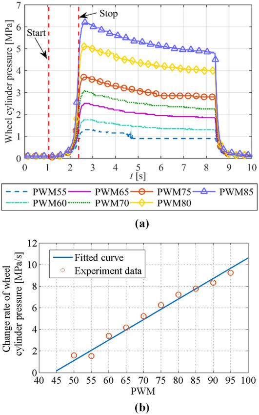
> REPLACE THIS LINE WITH YOUR PAPER IDENTIFICATION NUMBER (DOUBLE-CLICK HERE TO EDIT) < 2
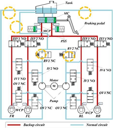
technique which is similar to [15], the pressure modulation the valves in the proposed system are normal on/off valves.
accuracy was improved. Nevertheless, because of the discrete Only two relief valves (RV1, RV2) are added, unlike the
nonlinearity of on-off valves, the existing control methods standard electronic stability program (ESP) systems [24], the
mentioned above can hardly achieve a desirable linear differences between proposed BBW system and conventional
performance as a proportional valve behaves. Moreover, the BBW system have been highlighted in Fig. 1. The pressures of
noise reduction has been rarely considered in the existing the master cylinder and each wheel cylinder are measured by
studies. the corresponding pressure sensors.
A novel quasi-BBW system and a linear control method for
on/off valves were proposed in [2, 19-22]. However, the
proposed system can only decouple the mechanical connection
between the braking pedal and the hydraulic brake circuits in
some specific cases. Moreover, the proposed linear control
method is an open loop method, which is sensitive to external
disturbances. Motivated by the system and the control method
in [2, 19-22], in this paper, a novel BBW system is designed
simply by adding conventional actuators and sensors to the
usual hydraulic layouts. To improve the pressure modulation
accuracy of the hydraulic control system and reduce noise, two
pressure modulation methods, namely, the hydraulic pump
based pressure modulation (HPBPM) and the close-loop
pressure-difference-limiting (CLPDL) modulation, are
proposed and compared. The HPBPM is developed to increase
the hydraulic braking modulation precision by coordinating the
hydraulic pump and corresponding solenoid valves, while
CLPDL leverages on the valve current control technology. The
main novelty and contribution of this work are as follows: 1) Fig. 1. Diagram of the structure of the proposed BBW system.
MC: master cylinder; MCP: master cylinder pressure sensor; PSS: braking
the novel BBW system is developed simply by adding
pedal stroke simulator; ISV: isolation valve; RV: relief valve; IV: inlet valve;
conventional actuators and sensors to the conventional OV: outlet valve; WCP: wheel cylinder pressure sensor; FR: front right wheel;
hydraulic component layout that is simpler than the system in FL: front left wheel; RL: rear left wheel; RR: rear right wheel; NO: normally
[23]; 2) two pressure modulation methods of the newly open valve; NC: normally closed valve.
developed BBW system, namely, HPBPM and CLPDL, are To achieve good tracking performance of the target pressure,
proposed, and the control performance and noise were are the wheel cylinder pressure should be modulated precisely. The
compared via HiL validation; and 3) the CLPDL control state machine for wheel cylinder pressure modulation is
method is applied to a brake blending control strategy of EVs, illustrated in Fig. 2. The wheel cylinder pressure is threshold
validating the effectiveness and feasibility of the CLPDL controlled and has three modes, including pressure increase,
pressure hold and pressure decrease. These modes can shift
method in actual implementation.
from one to another by judging the logic thresholds, which are
The remaining parts of this work are organized as follows: in
the various differences between the actual and target wheel
Section II, the system and working principle of the novel BBW
cylinder pressures. The operation principle of the developed
is described. In Section III, the HPBPM for the BBW system is BBW system is explained in details below.
proposed. In Section IV, the linear correlation between the
pressure difference across the valve and applied coil current is
analyzed, and the CLPDL method of the BBW system is
developed. In Section V, the performances with respect to
tracking control and noise level of the system under HPBPM
and CLPDL methods are compared; the effectiveness of the
CLPDL approach is demonstrated by a normal regenerative
braking scenario. In Section VI, the study’s conclusions are
provided.
II. DESCRIPTION OF THE NEWLY PROPOSED BBW SYSTEM
Fig. 2. State machine of the wheel cylinder pressure modulation (error:
A novel BBW system, which can be implemented on all difference between the actual and the target wheel cylinder pressures; brk_cmd:
types of vehicles, including traditional internal combustion driver braking intention that can be interpreted from the master cylinder
pressure).
engine (ICE) vehicles and different forms of electrified and
intelligent ones, is schematically depicted in Fig. 1. Unlike the During the normal brake mode, the four normally open
standard BBW system–for example, Toyota’s electronically isolation valves are activated and closed. Then, the master
controlled brake (ECB), [23]–the high pressure accumulator cylinder pressure, which represents driver’s deceleration
and linear valves are not needed in the proposed system; all of demand, is physically isolated from the brake pressures of the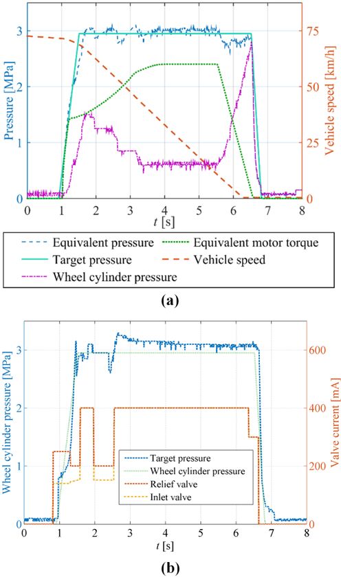
> REPLACE THIS LINE WITH YOUR PAPER IDENTIFICATION NUMBER (DOUBLE-CLICK HERE TO EDIT) < 3
downstream wheel cylinders. The braking fluid in the master
cylinder is directly passed into the pedal stroke simulator,
ensuring good brake pedaling feeling. As all of the wheel
cylinders have the same braking circuit layout, we take the
example of the front right wheel to explain the pressure
modulation process.
During the pressure increase process, two hydraulic pumps
are driven by the hydraulic pump-motor, which is controlled by Fig. 3. Overall controller configuration of pressure modulation.
PWM signals. Brake fluid is pumped directly from the tank The noise generated by the BBW system mainly originates
instead of the master cylinder, leaving the brake pedaling feel from two parts: the on/off valve and the hydraulic pump.
unaffected. The opening of the normally closed relief valve Compared to the valve generated noise, which is mostly
RV1 is controlled to keep the upper stream pressure of the inlet centralized in the high frequency range, the hydraulic pump
valve IV1 constant or at the upper limit, depending on the relief contributes more to low frequency noise. However, the high
valve (RV1) control method. By adjusting the opening of the frequency noise is most perceivable and intolerable for
inlet valve IV1, the wheel cylinder pressure can be modulated. passengers, especially when the opening of an on/off value is
The precise pressure increase is achieved by the coordinated being modulated frequently. Thus, an intuitive method to
control of the hydraulic pump, relief valve, and inlet valve. The reduce the annoying high frequency noise is to keep the PWM
detailed control algorithms for relief and inlet valves will be command of the inlet valve constant. The tracking performance
investigated in Sections 3 and 4. of the brake pressure in a wheel cylinder is guaranteed by
During the pressure decrease process, the hydraulic pumps modulation of the rotational speed of the pump-motor. To
stop and the relief valve RV1 is fully open. At the same time, illustrate the main idea of the HPBPM method, a simple but
the IV1 is fully closed, and the outlet valve OV1 is controlled valid spring and position model [17-22] is used. The dynamics
with PWM signals, which modulates the decreasing ratio of the of the wheel cylinder pressure pw and the displacement of the
brake pressure in wheel cylinder. The hydraulic fluid flows spring xw of the cylinder can be given by:
from the wheel cylinder to the tank directly. k
During the pressure hold process, both inlet valve IV1 and dpw w2 PWM dxw (1)
outlet valve OV1 are fully closed. The pump operates at a low
rw 100
speed, and the relief valve RV1 is opened to a certain level. This Q
dxw dt (2)
property keeps the pressure of the entire braking circuit above a rw2
certain level, which ensures responsiveness for the next where kw represents the stiffness coefficient of the spring, rw is
pressure increase process. the of the piston in the brake cylinder, σPWM (which varies within
As the pressure of the four wheel cylinders can be controlled 0-100) represents the value of the PWM signal for inlet valve,
independently, the proposed BBW system can also be used for and Q is the flow rate of the fluid passing through the valve.
other control functions, including anti-lock braking, traction According to the working principle of the hydraulic pump, the
control, and stability control program. In addition, this novel flow rate Q is expressed as,
design can be installed on vehicles with any type of braking Q 2 rpump
2
pump epumphyd _ motor (3)
circuit arrangement. Note that when the hydraulic pump fails,
as in a conventional vehicle, a backup circuit ensures the where rpump , ηpump, epump and ωhyd_motor are the radius of the
pressure build up by drivers; this is highlighted in Fig. 1. piston, efficiency, eccentricity, and rotational speed of the
pump-motor, respectively. By substituting equations (2) and (3)
III. CONTROL ALGORITHM DESIGN FOR HYDRAULIC PUMP in (1), the wheel cylinder pressure pw can be rewritten as
BASED PRESSURE MODULATION 2
2kw rpump e pump pump PWM
p&w hyd _ motor (4)
As mentioned in the introductory section, the following two rw4 100
performances must be guaranteed: first, the tracking
It can be seen from equation (4) that when the PWM
performance of the target wheel cylinder pressure; second, low
command value of the inlet valve is constant, and the dynamics
noise during BBW system operation. Thus, the control
of the pressure is directly decided by the rotational velocity of
algorithms for the on/off valves and hydraulic pump are worth
the pump-motor. Based on the property of PWM control, a
investigating. Two different control schemes have been
suitable PWM command value for the inlet valve should be
implemented; these schemes are presented in separate sections
chosen based on the following criteria. Regarding the first
(3 and 4).
criterion, the valve generated noise becomes most perceivable
The overall controller configuration for pressure modulation
and intolerable when the PWM command value is
of the two different scheme is illustrated in Fig. 3. In the first
approximately 50, at which the impact between valve coil and
scheme, we aimed at achieving the control goals by employing
seat is most dramatic.
the conventional PWM control technique for inlet valves, and a
Thus, less noise will be generated when the inlet valve PWM
newly proposed coil current control technique is implemented
command chosen is closer to 0 or 100. Regarding the second
in the second scheme. The first scheme is introduced as
criterion, because of the discontinuous property of the
follows.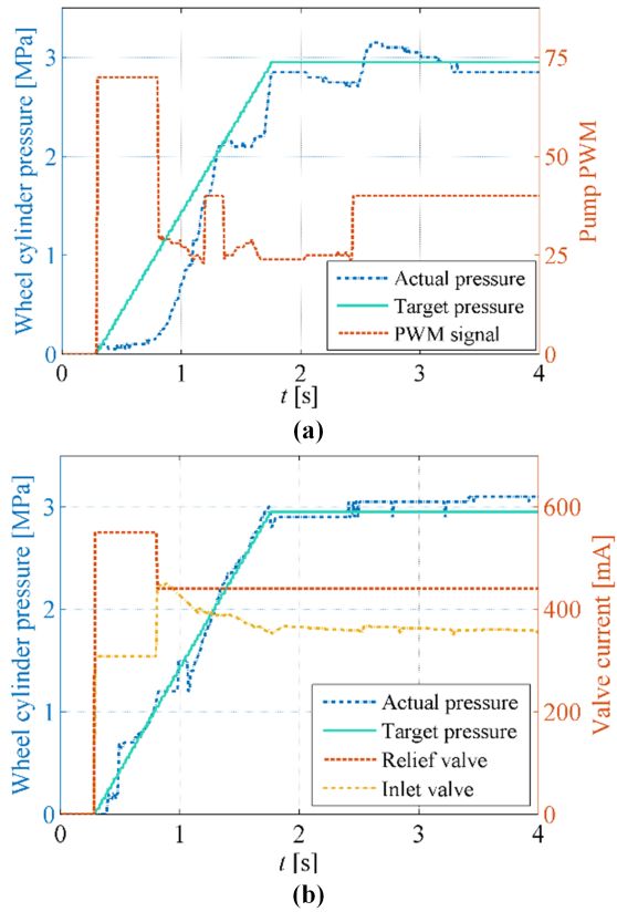
> REPLACE THIS LINE WITH YOUR PAPER IDENTIFICATION NUMBER (DOUBLE-CLICK HERE TO EDIT) < 4
hydraulic pump, pressure fluctuations will be generated. These IV. CONTROL ALGORITHM DESIGN FOR CLOSE-LOOP
fluctuations can be reduced by opening the inlet valve up to a PRESSURE-DIFFERENCE-LIMITING MODULATION
small level. In other words, the PWM command is supposed to The coil current based valve control method, which is
be close to 100 for a normally open inlet valve. different from the control method discussed in the last section,
is explored in this section. A close-loop modulation method is
developed based on the above discussed linear property for
on/off valves.
A. Linear modulation of on/off valve
The relative position of a normally open valve in closed-state
is illustrated in Fig. 6. Taking the lowest point which valve core
can reach as the origin, the local coordinate system of the
valves can be set up [22].
Fig. 6. Diagram of the coordinate system of the inlet valves.
Suppose the valve core comes in contact with the valve seat
after being energized, the axial forces applied on the valve can
be represented as
Fe Fs Fh FN sin 0 (5)
Fig. 4. (a) Relationship between the wheel cylinder pressure and the value of
where Fe, Fs, Fh, FN and α are the electromagnetic force, spring,
the PWM signal of the pump-motor (with the PWM value of the inlet valve at hydraulic force, supportive force, and valve seat cone angle,
80); (b) relationship between the wheel cylinder pressure and different PWM respectively [22].
command values of the pump-motor (with the PWM value of the inlet valve at The valve can be defined to be in a critical balanced position
80). when the following two conditions are satisfied: first, the valve
Figs. 4 (a) shows the relationship between the variation rate core is in contact with the valve seat; second, the contact force
of the brake pressure in wheel cylinder and the value of the between valve core and valve seat is zero, i.e., FN = 0. In this
PWM signal of the pump-motor. In both experiments, the inlet state, the valve core is just about to leave the valve seat and the
valve PWM value is set to 80, at which the noise is acceptable, force balance equation in (5) is simplified as
and the pressure fluctuation generated by the hydraulic pump is Fe Fs Fh 0 (6)
adequately suppressed. A linear relationship between the
variation rate of the wheel cylinder pressure and the value of the In equation (5), the only term that can be actively controlled
PWM signal for the pump-motor is observed, as shown in Fig. is the electromagnetic force Fe. Thus, to realize the critical
4 (b). This result validates the correctness of equation (4). balanced state, the electromagnetic force should be regulated in
To improve the tracking performance and robustness to a way that makes FN = 0. The electromagnetic force can be
external disturbances, a closed-loop control algorithm for the expressed as
hydraulic pump-motor is developed, as illustrated in Fig. 5. The ( NI ) 2
feed-forward lookup map is derived by experiments, as shown Fe (7)
2 Rg l
in Fig. 4. Because the wheel cylinder pressure can be obtained
by the pressure sensor, feedback control is utilized to offset the where I and N are the applied current and turns number of the
wheel cylinder pressure tracking error. Note that the relief coil, respectively. l and Rg are the length and magnetic
valve, which is controlled inactively, plays a role only of safety reluctance of air gap [22]. Then, we linearize equation (7) at a
outlet valves in the HPBPM control method. When the upper fixed operation point and reform it as:
stream pressure of the inlet valve exceeds 15 MPa, the relief
Fe Fe
valve will be pushed open to release the excess pressure. At Fe I I (t ) I (t ) xv xv ( t ) xv (t )
other times, the upper stream pressure of the inlet valve is equal I xv (8)
to the outlet pressure of the hydraulic pump. Ki I (t ) K xv xv (t )
> REPLACE THIS LINE WITH YOUR PAPER IDENTIFICATION NUMBER (DOUBLE-CLICK HERE TO EDIT) < 5
Fig. 5. Structural diagram of the PWM control algorithm for wheel cylinder pressure.
where xv is the displacement of the valve core, Ki and K xv are implements equation (16) in an open-loop manner as done in
[22], is not robust enough to disturbances. Second, unlike the
the first-order current-force and displacement-force coefficient.
case in [22], the value of the input pressure pin can be acquired
Note that, the displacement of valve core is xv 0 when the
accurately by using the pressure sensor. However, the pressure
critical balanced position is reached. Then, equation (8) can be of the valve input port cannot be measured in the proposed
simplified as BBW system. Thus, a close-loop tracking control algorithm is
Fe K i I (t ) (9) required to be designed for the proposed system, ensuring
Based on the definition of the OX coordinate in Fig. 6, the wheel cylinder pressure control accuracy and low noise
spring force of a normally open valve is expressed as generation.
Fs ks ( x0 xm xv ) (10)
B. Close-loop pressure-difference-limiting control
where x0 , xm and k s present the pre-tension displacement,
The structure of the CLPDL control for hydraulic pressure
maximum displacement and the stiffness of the return spring, modulation is shown in Fig. 7. To improve the robustness and
respectively. Besides, the spring force can be simplified in this accuracy of the control algorithm, a feed-forward and
state as feed-back scheme is employed. The current map which reflects
Fs ks ( x0 xm ) (11) the linear characteristics as equation (15) shows is derived from
When the valve core reaches the fully closed position, the the off-line experiments. A simple PI controller is utilized to
Fh is decided by the pressure drop p between valve inlet and eliminate external disturbances, such as temperature change
outlet and As , which is the surface area exposed to the fluid in and input pressure fluctuation.
pw_act can be obtained by the hydraulic pressure sensor
axial direction. Fh , As , and p are calculated as follows [22]: installed in the wheel cylinder. However, there is no sensor
Fh p As installed for measuring the inlet pressure pinput. Motivated by
(12)
As Rv2 (cos )2 the methods adopted in conventional BBW systems, the ideal
(13) pinput is to be controlled to a stable value. To achieve a stable
p pin pout upstream pressure for the inlet valve, a coordinate control
(14)
where Rv is the spherical radius in the valve core. strategy for the pump-motor and relief valve is developed.
Unlike the method in Section 3, the relief valve is controlled
Substituting equations (9), (11), and (12) into equation (6),
actively. Note that the relief valve is normally closed; thus, the
we can derive a linear correlation between coil current and the
relation shown in equation (16) needs to be rewritten as
pressure difference at valve’s critical balanced position [22]:
follows:
Ki k (x x ) ks _ relief ( x0 xm )
p I s2 0 m 2 (15) pout _ relief pin _ relief
Ki _ relief
(17)
Rv (cos )
2 2
Rv (cos ) Rv2_ relief (cos relief )2 Rv2_ relief (cos relief )2
I
Substituting equation (14) in equation (15), we can obtain the where pin_relief and pout_relief are the input and output pressures of
linear modulation property of valve outlet pressure by adjusting the relief valve, respectively. As indicated in Fig. 1, the output
the coil current, port of the relief valve is directly connected to the tank, where
Ki k (x x ) the pressure is zero; thus, pout _ relief 0 . The upstream pressure
pout pin I s2 0 m 2 (16)
Rv2 (cos )2 Rv (cos ) for the inlet valve is equal to pin _ relief ; therefore, equation (17)
If the input pressure pin can be measured or estimated, we can be simplified as follows:
will be able to address the output pressure tracking problem by
ks _ relief ( x0 xm ) Ki _ relief
calculating the coil current command value based on equation pin _ relief I (18)
(16) as has been done in [22]. However, the following two Rv _ relief (cos relief ) Rv _ relief (cos relief )2
2 2 2
problems must be addressed to achieve better tracking Based on the analysis above, by setting constant command
performance of the output pressure. First, as mentioned in the values for the relief valve and pump-motor, the stable upstream
introductory section, the control algorithm, which directly pressure for the inlet valve can be derived.> REPLACE THIS LINE WITH YOUR PAPER IDENTIFICATION NUMBER (DOUBLE-CLICK HERE TO EDIT) < 6
Fig. 7. Structural diagram of the close-loop CLPDL control algorithm for wheel cylinder pressure modulation.
According to the working principle of the
pressure-difference-limiting control, the upstream pressure for V. HARDWARE-IN-THE-LOOP TEST RESULTS
the input valve should be greater than or equal to the current In this section, to validate and compare the control
driver braking intensity. In the developed BBW system, performance of the proposed approaches, the HiL experiments
accurate modulation of the coil current is achieved by the were carried out with the new BBW system designed in Section
current control chip, whose best working region is from 100 2. The dSPACE Autobox serves as a real-time platform, in
mA to 600 mA. Thus, the optimal value of the pressure which the models of vehicle motion, electric motor and battery
difference is set within the range from 0 MPa to 4 MPa. A are running. Meanwhile, the real braking system including
switched coordinated control strategy for relief valve and hydraulic circuits, master and wheel cylinders, a vacuum
pump-motor has been designed, as shown in Fig. 8. The booster and brake pedal, is equipped in the test bench. Several
pressure increase mode has two sub-phases, denoted as low and key parameters of the models used in tests are listed in Table 1.
high braking intensity mode, which can realize the different
TABLE 1.
stable upper stream pressure for inlet valves. This property KEY PARAMETERS OF THE VEHICLE [25].
ensures that the current control chip works within its optimal
Parameter Value Unit
region and that there is enough up stream pressure for the inlet
Total mass (m) 1360 kg
valves. Hydraulic pump only works in the pressure hold and
increase modes. Because no noise is generated when the valve Wheel base (L) 2.50 m
is controlled by the current method, the noise is significantly Coefficient of air resistance (CD) 0.32 -
reduced with CLPDL control. Nominal radius of tire (r) 0.295 m
Gear ratio 7.881 -
The Freescale BA13 is used as the current control chip to
generate a stably controlled coil current. The proposed
hydraulic control algorithms are implemented in a real-time
controller. The controller communicates with the dSPACE
simulation platform through CAN (controller area network)
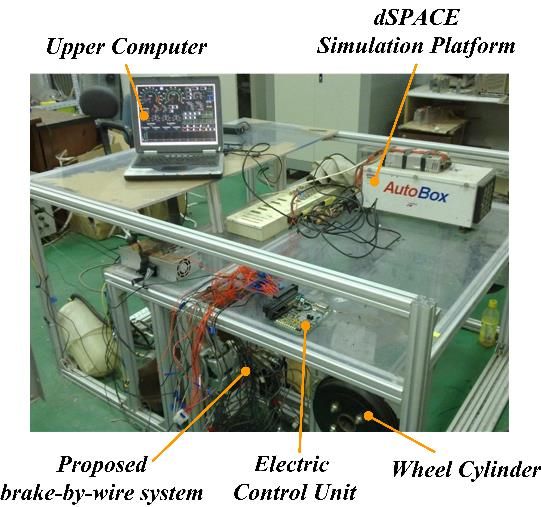
bus. Fig. 9 shows the overall experimental setup of the test
bench.
First, the tracking performances of a ramp input under
HPBPM and CLPDL control are compared. Next, a normal
regenerative braking scenario is used to test the feasibility of
the CLPDL control algorithm through actual implementation.
Fig. 8. Schematic diagram of the switch coordinated control strategy for the
relief valve and the pump-motor. Error: the difference between actual and target
wheel cylinder pressures; brk_cmd: driver braking intention, which could be
interpreted from the pressure in master cylinder; Pm: the pressure of master
cylinder; pump PWM cmd: the PWM command value of pump-motor; relief
valve current cmd: the current command value for relief valves.
Note that the current command value for relief valves
RV_cm1, RV_cmd2, and RV_cmd3, are different for the brake
cylinders in front and rear wheels. However, for the same wheel
cylinder, the relative relationship among the three values is the
same, which given by is 0> REPLACE THIS LINE WITH YOUR PAPER IDENTIFICATION NUMBER (DOUBLE-CLICK HERE TO EDIT) < 7
A. Comparison of HPBPM and CLPDL control the brake fluid to flow into the wheel cylinder. The coil current
So as to validate the performance of the designed modulation value of the relief valve remains constant, thereby cooperating
algorithms, the HiL testing scenario is set as: a normal with the hydraulic pump to achieve a stable upstream pressure
deceleration is taken the operation condition; the objective of the inlet valve. With the difference between the target and
value of the master cylinder pressure is set as a ramp input actual wheel cylinder pressures decreasing, the system
stabilizing at 3 MPa to mimic the normal braking intensity, and transitions into pressure hold mode, and the value of the coil
the adhesion coefficient is set at a high value of 0.8, indicating a current is modulated to be smaller, thereby fully closing the
dry surface. inlet valve.
The HiL test results with HPBPM are shown in Fig. 10(a). At The superior tracking performance of the CLPDL control
0.3 s, the target master cylinder pressure starts to increase and algorithm is evident from the comparison with the HPBPM
the hydraulic pump driven by the electric motor builds up the control algorithm. In addition, the CLPDL control algorithm, in
pressure rapidly during the time period from 0.3 s to 1.3 s. which there is no noise generated from the valves, provides
However, as the hydraulic pump requires 200-300 ms to more advantages over HPBPM control, in which PWM control
establish negative pressure, there exists a short delay before for the pump-motor and inlet valve is used. The tracking
pressure actually begins to build up at the beginning of braking. performances of the target wheel cylinder pressure with
This delay degrades the pressure tracking performance. It was HPBPM, CLPDL and conventional PWM control, which are
observed that the value of the PWM command decreases as the adopted in [2, 19, 20], are compared quantitatively in Table 2.
difference between actual and target pressures decrease. There The average absolute value and RMS of pressure tracking error
are two steps in the PWM signal for the pump-motor: one is with CLPDL control are 0.0875 MPa and 0.1049 MPa, which
from 1.3 s to 1.5 s, and the other is from 2.4 s to the end. The are 61.69% and 68.13%, respectively, better than those with
reason for the two steps is that the system is in the pressure hold HPBPM and 47.45% and 55.89%, respectively, better than
mode and the pump is operating at a constant speed to maintain those with conventional PWM control. This finding indicates
the pressure level of the whole braking circuit, thereby ensuring the enhancement of pressure modulation accuracy with the
the responsiveness for the next pressure increase mode. CLPDL control method.
TABLE 2.
COMPARISON OF PRESSURE TRACKING PERFORMANCE UNDER
CONVENTIONAL PWM, HPBPM AND CLPDL CONTROL METHODS.
Conventional
HPBPM CLPDL
PWM
Average absolute value of the
0.1665 0.2284 0.0875
pressure tracking error (MPa)
RMS (MPa) 0.2378 0.3291 0.1049
According to the above discussed HiL experimental results,
with HPBPM, although the system noise is reduced compared
to that with conventional PWM control for the inlet valve, the
tracking performance of the target pressure is not guaranteed.
The average absolute value and RMS of pressure tracking error
with HPBPM control are 37.18% and 38.39%, respectively,
which are worse than those with conventional PWM control.
Thus, from both perspectives of control accuracy and noise
reduction, the newly proposed CLPDL control appears to be an
effective method to address the wheel cylinder pressure
modulation problem.
B. Brake blending algorithm based on CLPDL modulation
The brake blending performance between regenerative
braking and hydraulic braking has a significant effect upon the
regeneration efficiency and brake safety. Thus, the requirement
of hydraulic pressure modulation accuracy is crucial. In
addition, unlike emergency conditions, such as anti-lock
Fig. 10. (a) HiL test results of the hydraulic pump based pressure modulation
for the pressure tracking scenario; (b) HiL test results of the CLPDL for the
braking, brake comfort and noise level, are also evaluated
pressure tracking scenario. during regenerative braking, making the hydraulic pressure
modulation even more difficult. To verify the performance of
The same HiL test scenario is implemented to test the
the CLPDL algorithm in real world applications, a typical brake
CLPDL control algorithm. The experimental data are presented
blending test of EVs is conducted on the HiL test bench. The
in Fig. 10(b). As the target wheel pressure increases, the coil
set-up of the testing scenarios is the same as the one adopted in
current of the inlet valve jumps from 0 mA to 300 mA, allowing
the tracking performance test. The brake maneuver is initialized> REPLACE THIS LINE WITH YOUR PAPER IDENTIFICATION NUMBER (DOUBLE-CLICK HERE TO EDIT) < 8
with the vehicle speed of 72 km/h. The target vehicle is a The HiL tests results for brake cylinders in rear axle are
front-wheel driven one, which equips with a centralized electric shown in Fig. 11 (b). Since there is no regenerative braking
motor. The same brake blending control strategy as introduced applied on the rear axle, the control task is same as those
in [21, 22, 25] is employed. The only modification is the illustrated in Section 5.A. As shown in Fig. 11 (b), the target
replacement of the conventional PWM valve control with the pressure of the rear wheel cylinder is well-tracked. The overall
CLPDL control algorithm. The details of the brake blending experimental results show that the target brake pressure is
algorithm are presented in [21, 22, 25]. followed very well through valve modulation with the proposed
The HiL test results for the front axle are shown in Fig. 11 approach, and the blended braking brakes at the front wheels
(a). At approximately 0.8 s, the target master cylinder pressure are coordinated well, thereby validating the effectiveness of the
begins to increase. The electric motor applies the braking CLPDL control algorithm of the hydraulic brake pressure.
torque gradually on the front axle. According to the brake
blending strategy, the hydraulic braking, which is under the VI. CONCLUSIONS
control of the CLPDL algorithm, decreases when the High-precision control of mechatronics is an important
regenerative braking torque increases. After 1.5 s, the target foundation of the development of safe, smart and sustainable
value of master cylinder pressure remains stable at CPS [26-31]. In this paper, a typical safety-critical CPS, i.e. the
approximately 3 MPa, and accordingly the hydraulic brake BBW system, was introduced. Compared to the existing BBW
pressure is modulated dynamically under CLPDL control. system, the newly developed system enjoys the advantage of a
During the pressure increase phase, the outlet valve of the simple structure and low cost because only conventional valves
brake cylinder is not energized. Starting from 6.5 s, the and sensors are added to the usual hydraulic layouts. Two
regenerative braking torque gradually decreases and finally pressure modulation methods, namely, the HPBPM and
down to zero because of the characteristics of the electric CLPDL modulation, were proposed to improve the modulation
motor. Thus, the hydraulic brake pressure needs to be increased precision of hydraulic brake pressure and reduce valve’s
accordingly to fulfill the brake demand. Under the control of operation noise as well. Experiments were conducted in HiL
CLPDL, the hydraulic braking pressure changes smoothly and test rig to demonstrate the performance of the proposed control
the driver’s braking intension is well satisfied. methods. Experimental results showed that, in spite of the
reduction in noise in the HPBPM control method, when
compared to the conventional PWM control, control accuracy
is not guaranteed. The CLPDL method achieves both good
performance of tracking target pressure and reduced noise. To
further validate the feasibility of the newly proposed BBW
system and the CLPDL control method, a typical regenerative
braking scenario was utilized. The CLPDL control method was
implemented within a regenerative braking strategy. The HiL
test results illustrated that both the front and rear wheel
cylinders fulfilled the driver braking intention and that the
regenerative braking and hydraulic braking cooperate well with
each other. For the future work, real vehicle tests will be
conducted, and qualitative comparisons between proposed
BBW system and existed BBW systems will be explored.
ACKNOWLEDGMENT
The research is supported by the Young Elite Scientist
Sponsorship Program by CAST (No. 2017QNRC001), the
National Natural Science Foundation of China (No. 51722809),
and the National Key Research and Development Program of
China (No. 2017YFB0103604, No. 2016YFE0206800).
REFERENCES
[1] Zhou, Q., Zhang, Y., et al, Cyber-Physical Energy-Saving Control for
Hybrid Aircraft-Towing Tractor based on Online Swarm Intelligent
Programming. IEEE Transactions on Industrial Informatics, 2017.
[2] J. Zhang, Y. Li, C. Lv, Y. Yuan, “New regenerative braking control
strategy for rear-driven electrified minivans,” Energy Convers. Manag.t,
vol. 82, pp. 135-145, 2014.
[3] Hu, J.S., Wang, Y., Fujimoto, H. and Hori, Y. Robust yaw stability
control for in-wheel motor electric vehicles. IEEE/ASME Transactions on
Fig. 11. (a) HiL test results of the CLPDL-based brake blending control Mechatronics, 2017.
strategy for the front axle; (b) HiL test results of the CLPDL-based brake [4] Lv, C., Xing, Y., Zhang, J., Na, X., Li, Y., Liu, T., Cao, D. and Wang,
blending control strategy for the rear axle. F.Y. Levenberg-Marquardt Backpropagation Training of Multilayer> REPLACE THIS LINE WITH YOUR PAPER IDENTIFICATION NUMBER (DOUBLE-CLICK HERE TO EDIT) < 9
Neural Networks for State Estimation of A Safety Critical Cyber-Physical [27] Lv, C., Cao, D., Zhao, Y., Auger, D. J., Sullman, M., et al. Analysis of
System. IEEE Transactions on Industrial Informatics, 2017. autopilot disengagements occurring during autonomous vehicle testing.
[5] L. Yu and T. Chang, "Zero vibration on-off position control of dual IEEE/CAA Journal of Automatica Sinica, 5(1), 58-68, 2018.
solenoid actuator", IEEE Trans. Ind. Electron., vol. 57, no. 7, pp. [28] Lv, C., Liu, Y., Hu, X., Guo, H., Cao, D., Wang, F. Y. Simultaneous
2519-2526, 2010. observation of hybrid states for cyber-physical systems: A case study of
[6] F. Munoz, W. Li, et al. Analysis of Magnetic Interaction in Remotely electric vehicle powertrain. IEEE transactions on cybernetics, 2017.
Controlled Magnetic Devices and Its Application to a Capsule Robot for [29] Lv, C., Zhang, J., Li, Y. Yuan, Y. Mechanism analysis and evaluation
Drug Delivery. IEEE/ASME Transactions on Mechatronics, 2017 methodology of regenerative braking contribution to energy efficiency
[7] Tang, X., Du, H., Sun, S., Ning, D., Xing, Z. and Li, W. Takagi–Sugeno improvement of electrified vehicles. Energy Conversion and
Fuzzy Control for Semi-Active Vehicle Suspension With a Management, 92, pp.469-482, 2015.
Magnetorheological Damper and Experimental Validation. IEEE/ASME [30] Lv, C., Zhang, J. Li, Y. Extended-Kalman-filter-based regenerative and
Transactions on Mechatronics, 22(1), pp.291-300, 2017. friction blended braking control for electric vehicle equipped with axle
[8] Lv, C., Wang, H. and Cao, D. High-precision hydraulic pressure control motor considering damping and elastic properties of electric powertrain.
based on linear pressure-drop modulation in valve critical equilibrium Vehicle System Dynamics, 52(11), pp.1372-1388, 2014.
state. IEEE Transactions on Industrial Electronics, 64(10), [31] Li, Y., Hansen A., Hedrick J. K., Zhang J. A receding horizon sliding
pp.7984-7993, 2017. control approach for electric powertrains with backlash and flexible
[9] T. Oshima, N. Fujiki, S. Nakao, T. Kimura, “Development of an half-shafts. Vehicle System Dynamics, 55 (12), pp. 1823-1841, 2018.
Electrically Driven Intelligent Brake System,” SAE Int. J. Passeng. Cars,
vol. 4, no. 1, pp. 399-405, 2011.
[10] V. Milanes, C.Gonzalez, E. Naranjo, E. Onieva, T. De Pedro, Yutong Li is currently a Postdoc in Department of
“Electrohydraulic braking system for autonomous vehicles,” Int. J. Transportation at Tongji University. He received his B. Eng.
Autom. Technol., vol. 11, no. 1, pp. 89–95, 2010. (2012) from the Jilin University, and his Ph.D. (2017) from
[11] C. Rossa, A. Jaegy, J. Lozada, A. Micaelli, “Design Considerations for Tsinghua University. His research interests broadly include
Magnetorheological Brakes,” IEEE/ASME Trans. Mechatron., vol. 19, topics in Decision making and control under uncertainties
no. 5, pp. 1669-1680, 2014. (application to autonomous vehicles), Simulation based
[12] J. Bae, Y. Kim, Y. Son, H. Moon, C. Yoo, J. Lee, “Self-Excited Induction verification and validation, Powertrain architecture
Generator as an Auxiliary Brake for Heavy Vehicles and Its Analog optimization for performance and fuel economy.
Controller,” IEEE Trans. Ind. Electron., vol. 62, no. 5, pp. 3091-3100,
2015. Chen Lv is an Assistant Professor of School of Mechanical
[13] S. Saric, A. Bab-Hadiasher, R. Hoseinnezhad, “Clamp-force estimation and Aerospace Engineering and School of Electrical and
for a brake-by-wire system: A sensor-fusion approach,” IEEE Trans. Veh. Electronic Engineering, Nanyang Technological University,
Technol., vol. 57, no. 2, pp. 778-786, 2008. Singapore. He received the Ph.D. degree at Department of
[14] R. Champagne, S. Stephens, “Optimizing valve actuator parameters to Automotive Engineering, Tsinghua University, China in
enhance control valve performance,” ISA Trans., vol. 35, no. 3, pp. 2016. He was a joint PhD researcher at EECS Dept.,
217–23, 2005. University of California, Berkeley, USA. His research
[15] S. Choi, D.Cho,” Control of wheel slip ratio using sliding mode controller focuses on cyber-physical system, hybrid system, advanced
with pulse width modulation,” Veh. Syst. Dyn., vol. 32, pp. 267–284, vehicle control and intelligence, where he has contributed
1999. over 40 papers and obtained 11 granted China patents.
[16] K. Ahn, S. Yokota, “Intelligent switching control of pneumatic actuator
using on/off solenoid valves,” Mechatronics, vol. 15, no. 6, pp. 683-702, Junzhi Zhang received the B.E. degree in
2005. Transportation Engineering and his M.S. and Ph.D.
[17] W. Wang, J. Song, L. Li, H. Li, “High speed on–off solenoid valve with degree in Vehicle Engineering from the Jiliin University
proportional control based on high frequency PWM control,” Journal of of Technology, Changchun, China in 1992, 1995 and
Tsinghua University (Science and Technology), vol.51, no. 5, 2011. 1997, respectively. From 1998-1999, Dr. Zhang was a
[18] X. Zhao, L. Li, J. Song, C. Li, X. Gao, “Linear Control of Switching Research Associate in Department of Automotive
Valve in Vehicle Hydraulic Control Unit Based on Sensorless Solenoid Engineering in Tsinghua University, Beijing, China. In
Position Estimation,”2017. 1999, Dr. Zhang joined Tsinghua University and founded
[19] J. Zhang, C. Lv, J. Gou, D. Kong, “Cooperative control of regenerative the Hybrid Powertrain Systems Laboratory whose major
braking and hydraulic braking of an electrified passenger car,” Proc. Insti. research interests include modeling, control and diagnosis of hybrid, electric
Mech. Eng., Part D: J. Autom. Eng., vol. 226, no. 10, pp. 1289-1302, vehicle. Dr. Zhang become a full professor in Department of Automotive
2012. Engineering in Tsinghua University in 2008. Dr. Zhang is the author or
[20] Lv, C., et al. "Brake-Blending Control of EVs." In Modeling, Dynamics co-author of more than 50 peer-reviewed publications and 20 Chinese patents.
and Control of Electrified Vehicles, pp. 275-308. 2018.
[21] J. Zhang, C. Lv, X. Yue, Y. Li, Y. Yuan, “Study on a linear relationship Yun Zhang is currently a researcher in Department of
between limited pressure difference and coil current of on/off valve and Transportation at Tongji University. She received her B.S.
its influential factors,” ISA Trans., vol. 53, no. 1, pp. 150-161, 2014. and Ph. D. degree in the School of Aerospace Engineering
[22] C. Lv, J. Zhang, Y. Li, D. Sun, Y. Yuan, “Hardware-in-the-loop from Tsinghua University in 2012 and 2017. Her research
simulation of pressure-difference-limiting modulation of the hydraulic interests lie in the broad area of motion planning, and
brake for regenerative braking control of electric vehicles”, Proc. Insti. large-scale discrete element system simulation, with
Mech. Eng., Part D: J. Autom. Eng., vol. 228, no. 6, pp. 649-662, 2014. applications to autonomous transportation systems.
[23] M. Soga, M. Shimada, J. Sakamoto, A. Otomo, “Development of Vehicle
Dynamics Management System for Hybrid Vehicles - ECB System for
Improved Environmental and Vehicle Dynamic Performance,” SAE
Technical Paper 2002-01-1586, 2002. Wanjing Ma received his B.S. degree in civil engineering
[24] A. van Zanten, “Bosch ESP Systems: 5 Years of Experience,” SAE from Chang’an University, China, in 2001, and M.S., and
Technical Paper 2000-01-1633, 2000. Ph.D. degree in transportation engineering from Tongji
[25] J. Zhang, Y. Li, C. Lv, J. Gou, Y. Yuan, “Time-varying delays University, China, in 2004 and 2007, respectively.
compensation algorithm for powertrain active damping of an electrified He is currently a Professor and vice dean of the college of
vehicle equipped with an axle motor during regenerative braking”, Mech. Transportation Engineering at Tongji University. His
Syst. Signal Process., 2017. research focuses on traffic operation and control, connected
[26] Lv, C., Xing, Y., Lu, C., Liu, Y., Guo, H., Gao, H. and Cao, D. vehicles, and shared mobility.
Hybrid-Learning-Based Classification and Quantitative Inference of
Driver Braking Intensity of an Electrified Vehicle. IEEE Transactions on
Vehicular Technology, 2018You can also read