HGCROC: the front-end readout ASICs for the CMS High Granularity Calorimeter - CERN Indico
←
→
Page content transcription
If your browser does not render page correctly, please read the page content below
HGCROC: the front-end readout ASICs for
 the CMS High Granularity Calorimeter
 Damien Thienpont, on behalf of the CMS collaboration

 G. Bombardi, F. Bouyjou, E. Delagnes, P. Dinaucourt, F. Dulucq, M. El Berni, M. Firlej,
 T. Fiutowski, J. Gonzalez, F. Guilloux, M. Idzik, C. de La Taille, A. Marchioro, J. Moron,
 L. Raux, K. Swientek, D. Thienpont, T. Vergine

 Organization for Micro-Electronics desiGn and Applications
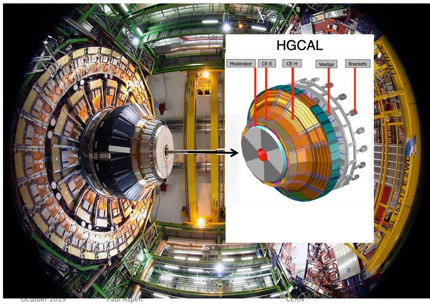
HGCAL: CMS EndCap Calorimeters for the LHC Phase-II upgrade HGCAL covers 1.5 < eta < 3.0 Full system maintained at -30°C ~ 640 m² of silicon sensors, 6.1M Si channels, 0.5 or 1.1 cm² cell size ~ 370 m² of scintillators, 240k scint-tile channels Data readout from all layers Trigger readout from alternate layers in CE-E and all in CE-H Active Elements Electromagnetic calorimeter (CE-E): Si, Cu/CuW/Pb absorbers Hadronic calorimeter (CE-H): Si & scintillator, steel absorber LD HB x3 HGCROC New Front-end electronics Two versions: Silicon and SiPM Rad.tolerant (200 Mrad, 1.1016 neq / cm²) Power consumption: 20 mW per channel Tile board HD HB Noise: 0.4 fC x1 H2GCROC x6 HGCROC Charge: 0.2 fC to 10 pC Pileup mitigation: Fast shaping (peak < 25 ns), precise timing capability (25 ps) TIPP 2021 2
HGCROC2 overview
Overall chip divided in two symmetrical parts
• 1 half is made of:
 – 39 channels: 18 ch, CM0, Calib, CM1, 18 ch (78 channels in total)
 – Bandgap, voltage reference close to the edge
 – Bias, ADC reference, Master TDC in the middle
 – Main digital block and 3 differential outputs (2x Trigger, 1x Data)
Measurements
• Charge
 – ADC (AGH): peak measurement, 10 bits @ 40 MHz, dynamic range
 defined by preamplifier gain
 – TDC (IRFU): TOT (Time over Threshold), 12 bits (LSB = 50ps)
 – ADC: 0.4 fC resolution. TOT: 2.5 fC resolution
• Time
 – TDC (IRFU): TOA (Time of Arrival), 10 bits (LSB = 25ps)
Two data flows
• DAQ path
 – 512 depth DRAM (CERN), circular buffer
 – Store the ADC, TOT and TOA data
 – 2 DAQ 1.28 Gbps links
• Trigger path
 – Sum of 4 (9) channels, linearization, compression over 7 bits
 – 4 Trigger 1.28 Gbps links
Control
• Fast commands
 – 320 MHz clock and 320 MHz commands
 – A 40 MHz extracted, 5 implemented fast commands
• I2C protocol for slow control
Ancillary blocks
• Bandgap (CERN)
• 10-bits DAC for reference setting
• 11-bits Calibration DAC for characterization and calibration
• PLL (IRFU)
• Adjustable phase for mixed domain TIPP 2021
 3
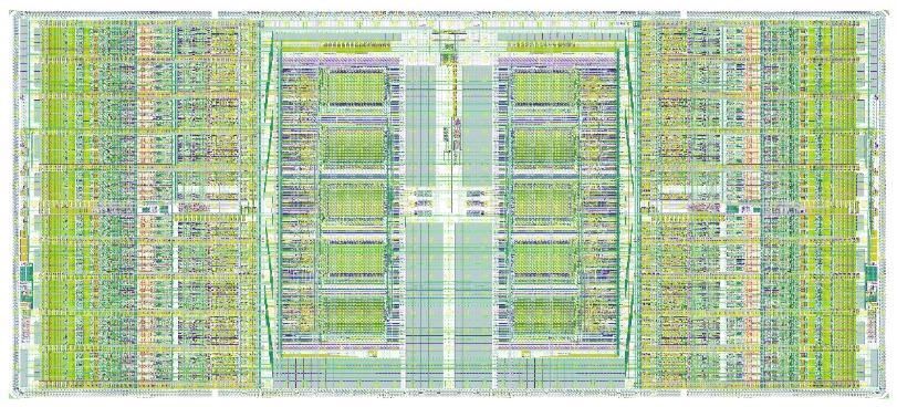
HGCROC2 floorplan

• Two half-chips + common digital blocks (I2C, fast commands, PLL, 1.28 Gb serializers)
 – Each half hosts 8 blocks of 4 channels + 2 common mode blocks
 – Digital data processing : trigger sums and (partial) data storage in DRAM
 – TSMC 130 nm 14 mm
 4 channels + SC I2C
 FC

 r
 e PLL
 f
 7 mm e bias serial
 r izers
 e
 n
 c
 e
 s

 TIPP 2021
 4
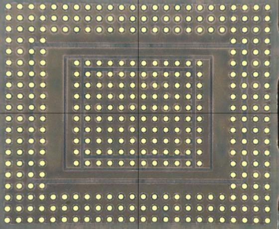
Packaging

• C4 bump bonding
• 2 BGA packages fabricated:
 – High Density (0.6 mm pitch) for Hexaboard with ~400 channels (120 µm Si
 sensors)
 – Low Density (0.8 mm pitch) for Hexaboard with ~200 channels (200 µm and 300
 µm Si sensors) and Tileboards with ~70 channels

 TIPP 2021
 5
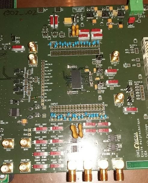
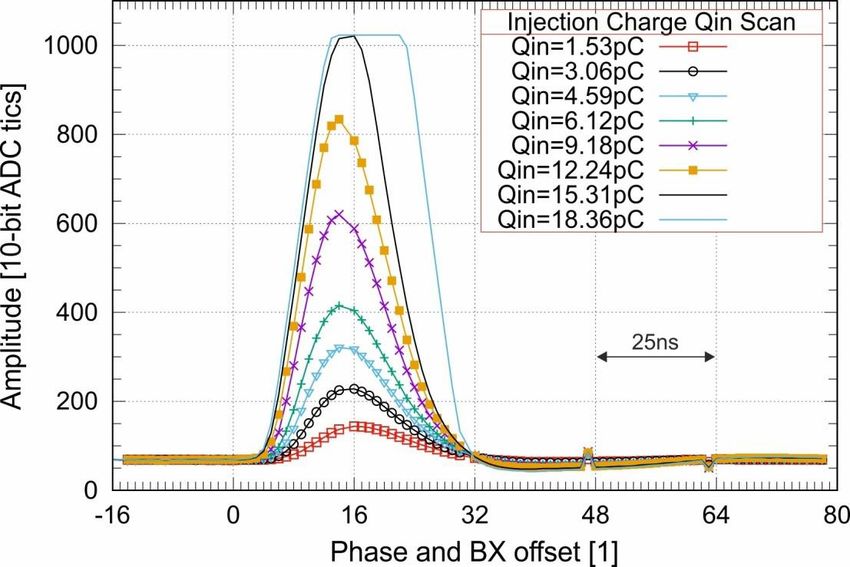
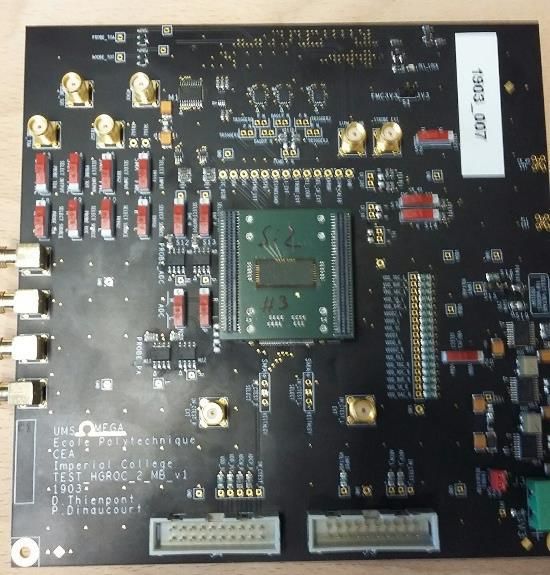
Test boards and signal
Flip-Chip on mezzanine HD BGA board HD BGA on mezzanine

 Version 2
 125 fC
 Gain = ~0,18 fC/ADCU

 • Separates effects from the BGA substrate and PCB
 • Rising time (10-90 %): ~ 15 ns
 • Falling time (10-90 %): ~ 30 ns, < 20 % at BX+1
 • Good uniformity over the channels
 • Digital 40 MHz clock coupling on the analog signal on the HD BGA board: digital noise (slide 11)

 TIPP 2021
 6
Charge ADC (0 – 160 fC)

• Two 10b-DAC to globally set the pedestal to a
 wanted level
• 5b-DAC to reduce dispersion per channel
 – From ~ 100 ADCu dispersion to ~ 5 ADCu
• Good linearity within +/- 0.5%
 – 1.6 fC (~1 MIP) linearity for the typical gain
• ~ 0.3 fC resolution with 50 pF input capacitor

 ~ 0.3 fC

 TIPP 2021
 7
Charge: TOT range (160 fC – 10 pC)

Charge measurement from TOT when preamplifier
saturates
• 160 fC to 10 pC (for the typical preamplifier gain) 150 ns
 – 12 bits over 200 ns
 – 50 ps binning
• Linearity
 – < 2% linearity
 – Better with input capacitor (as expected)
 – Small residual wiggles on TOT due to digital noise on preamplifier input
• Resolution around the LSB (~ 50 ps)
 – Some peaks due to outliers (understood and fixed)
 0,1 %

 1 LSB

 TIPP 2021
 8
Noise

• Measured noise with 50 pF input cap = 0.3 fC 0 pF Cdet 47 pF Cdet 68 pF Cdet
 (~ 2000 electrons) (0.7 nV / √Hz) High gain ENC
 Typical gain ENC
 900 electrons
 1250 electrons
 2000 electrons
 2000 electrons
 2750 electrons
 2700 electrons
• Very low correlated noise contribution: ~ 0.1 Low gain ENC 2200 electrons 2800 electrons 3400 electrons

• Coherent noise extracted by comparing direct TOA FOM (1) NA
 2.5 ns/fC (FlipChip)
 3 ns/fC (FlipChip)
 3 ns/fC (BGA)
 and alternate sums on n channels (n = 72): 25 ps (FlipChip)
 TOA noise floor (1) 20 ps 25 ps (FlipChip)
 = ; = −1
 [ ] 0.8 ns (FlipChip)
 25 ps (BGA)
 2.5 ns (FlipChip)
 TOA Time-Walk 4 ns (FlipChip)
 – Incoherent noise = ( )/√ 4 ns (BGA) 6.5 ns (BGA)

 – Coherent noise CN = − /

 Equivalent Noise Charge wrt. sensor capacitance Correlation matrix Coherent vs. incoherent noise

 IN: 0.3 fC
 CN: 0.06 fC

 TIPP 2021
 9
Digital noise

• A 40 MHz modulation is visible on the analog signals
 • Comes from digital current spikes on preamp ground
 node
 • 10 µV on ground give 1 ADC count
 • BGA worse than flip chip
 • BGA substrate optimised, improvements made by
 optimizing decoupling & the pcb ground impedance
 • Further improved by removing decoupling caps !
 • Reduces digital current spikes (inductance) [ns]

• This provides recommendations for the Hexaboard
 design
 – Very delicate design!

 [ns]
 TIPP 2021
 10
Timing performance
• Minimum Charge providing a TOA measurement is 20 fC, limited by the digital coupling
 170 [ ]
• = + 400 [ ] : 2.5 ns w/o detector cap., ~ 5 ns with 50 pF input capacitor
 [ ]
 2[ ]
• = + 22 [ ]
 [ ]

 Time Walk

 20 fC

 Timing jitter

 TIPP 2021 11
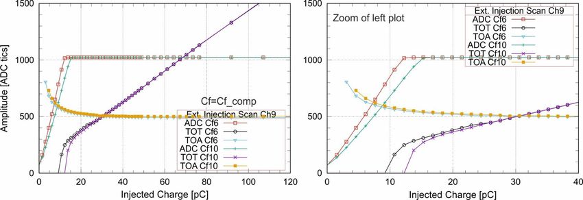
Trigger characterization

 • Charge linearization over ADC and TOT range
 • Sum by 4 / 9 (19b / 21b)
 • Compressed to 7 bits: 4b exponent + 3b mantissa

 ‘-’ : ADC [ADC counts]
ADC counts

 ‘-’ : TOT [TOT counts]
 ‘- - ’: Trigger data before compression
 (calculated from DAQ data)
 ‘-’ : Trigger Data [ADC counts]

 160 fC 1.2 pC
 TIPP 2021
 12
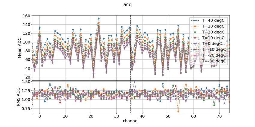
Bandgap and temperature measurements • Readout is DC coupled to the shaper output temperature sensitivity mitigation mandatory • Bandgap value moves over 2mV between -40°C and +40°C, but lower shift around -20°C • Increasing to ~ 6-8 mV after 300 Mrad • Pedestals • 1 ADC/°C at room temperature • ~ 0.4 ADC/°C around -30°C (Would be around 5 ADC/°C without mitigation) Pedestals value as a function of temperature Gain as a function of temperature BGA TIPP 2021 13
Analog Channel Overview: SiPM version

• H2GCROC2 (SiPM version) = HGCROC2 + input current conveyor
 – Heidelberg university design
• 2.5 V input stage for overvoltage adjustment

 TIPP 2021
 14
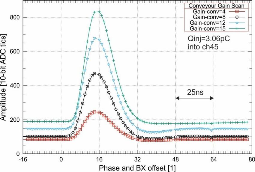
SiPM version measurements
H2GCROC2 measurements:
• Good shape as expected 1 pe. 2 pe.
• Adjustable conveyor gain
 ped.
• Dynamic range as expected: TOT (12bit) – 300pC aimed
 3 pe.

• Single-Photon Spectra (SPS): ~10 ADC tics
 • 4V overvoltage, conveyor gain = 12
 • Gain: ~ 10 ADC counts

 TIPP 2021
 15
TID and SEU tests
TID: thinned chip (70 µm) SEE: 2 campaigns at Louvain (Nov 2019 &
• 3 campaigns at CERN: Feb 2020)
 • Si-version at room temperature (Oct 2019) • Heavy ions LET 5 – 45 MeV
 • Si-version at cold (Mar & Jun 2020)
 • SiPM-version at room temperature (Aug 2020) • I2C acted as expected: cross section follows
• Irradiation up to 310 Mrad (5 Mrad for SiPM) the usual curve and no errors recorded
• The chip still works after annealing when auto-correction set. Flips < 2 E-7
 Hz/chip
 • Bit shifting in the DAQ link (no triplicated
 Serializer in HGCROCv2)
 • No signs of latch-up effects
 • No flips seen in ADC/TOA/TOT data

 Last run after 318 Mrad

 TIPP 2021
 16
HGCROC3: final version
Analog Upgrades:
• Increased sensor leakage current compensation
• Increase resolution (12bit) of DAC and phase
 shifter for calibration
• TOA calibration with a Randomized Pulse
 Generator Submitted mid-Dec 2020
Triplicated Logic
• Memory pointers and calculation logic
High Speed Serial links
• SEE tolerant
Control
• SEU tolerant Fast commands
• SEU tolerant I2C Module for slow control
Memory blocks
• Adds trigger derandomizing buffer for DAQ path
• Custom Hamming Encoding at the entry of
 Circular Buffer
• Hamming Decoding after the L1 FIFO
Checksum
• CRC-32 Checksum Encoding before serialization

 : Tripled Module
 TIPP 2021
 17
Summary
• With HGCROC2, a big step has been taken to reach the HGCAL’s requirements. It is probably one of the most
 complex chips ever designed for imaging calorimetry: high dynamic charge, precision timing measurements,
 high speed links, a lot of digital, harsh radiation environment…

• Measurements now well advanced on both Silicon and SiPM versions @CERN, LLR, IRFU, Desy and OMEGA
 – Charge performance reaches the specification: 1 % linearity, for both ADC and TOT
 – Timing performance: time walk calibration feasible, jitter below 25 ps

• Digital coupling
 – Good performance at chip level
 – Stringent requirement on PCB design: low ground impedance and optimized power decoupling
 – First studies on the Hexaboard and Tileboards started

• TID and SEE campaign show very good performance
 – SEEs appear only in the non-triplicated parts of the chip (as expected)
 – SEU errors on the slow-control parameters < 1e-7 Hz

• HGCROC3 will be the final version…
 – Now at packaging, awaited end-May
 TIPP 2021
 18
Backup slides

 TIPP 2021
 19
Analog Channel Overview: Silicon version
• Calibration pulser, 0.5pF and 8 pF calibration cap. • Compensation for the leakage current, 10 µA max. (not shown in
• Preamp : adjustable gains for 80, 160 and 320 fC ranges the figure)
• Tunable TOT threshold • Sallen Key shaper RC4, tp < 25 ns, tunable (~20%) with 2 bits,
 BX+1/BX
Trigger path

• The chip provides compressed data of the charge to the
 L1 trigger processing
 – Charge linearization over ADC / TOT range
 – Sum of 4 (or 9) channels (depending on the sensor)
 – Charge compression to fit the bandwidth (4b Exponent + 3b
 Mantissa)
 – 4 E-link transmitters, CLPS @ 1.28 Gbps

 HGCROC2 integrates 72 channels to readout
 • 192 channels sensor with a 64-ch configuration
 • 432 channels sensor with a 72-ch configuration
 TIPP 2021
 21
From HGCROC2 to HGCROC3

 V2
• Sharp eye needed to distinguish the
 differences!
 – Same size/pinout/package
 – Small improvements in analog part
 – Adds derandomizer after L1 DRAM
 – SEU mitigation done in digital part
 – More robust I²C and fast command decoder
 – Final functionality V3

• Completed end-october
 – Reviewed Dec 1st
 – Submitted mid-Dec

 TIPP 2021
 22
TDC calibration • Channel-wise TDC made of a fine TDC (3 bits), a coarse TDC (5 bits) and a counter (2 bits) – Works only when a ToA (or a ToT) occurs • Two servo-controlled master TDCs allow to control speed of channel-wise TDCs – First adjustment allow to configure the Master TDC (1 2) – External pulse injection used here : will be replaced by a Random Pulse Generator (RPG) in V3 1 2 • Then channel-wise adjustment allows to achieve the best performances (~1 LSB INL) 3 TIPP 2021 23
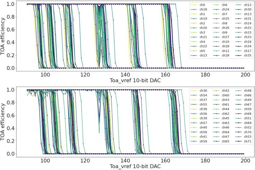
Timing performance – S-curve

• S-curves show the ToA efficiency as a function
 of the charge
• Minimum charge providing ToA events is 20 fC
 – Limited by the digital coupling

 TIPP 2021
 24
You can also read