Globally Consistent Depth Labeling of 4D Light Fields
←
→
Page content transcription
If your browser does not render page correctly, please read the page content below

Globally Consistent Depth Labeling of 4D Light Fields

                                       Sven Wanner and Bastian Goldluecke
                                   Heidelberg Collaboratory for Image Processing

                         Abstract

   We present a novel paradigm to deal with depth recon-
struction from 4D light fields in a variational framework.
Taking into account the special structure of light field data,
we reformulate the problem of stereo matching to a con-
strained labeling problem on epipolar plane images, which
can be thought of as vertical and horizontal 2D cuts through
the field. This alternative formulation allows to estimate ac-
curate depth values even for specular surfaces, while simul-
                                                                     Figure 1. Our novel paradigm for depth reconstruction in a light
taneously taking into account global visibility constraints in
                                                                     field allows to estimate highly accurate depth maps even for spec-
order to obtain consistent depth maps for all views. The re-         ular scenes.
sulting optimization problems are solved with state-of-the-
art convex relaxation techniques. We test our algorithm on a         sisting of a single moving camera [20], which is however
number of synthetic and real-world examples captured with            restricted to static scenes, see figure 2. Recently, however,
a light field gantry and a plenoptic camera, and compare             the first commercial plenoptic cameras have become avail-
to ground truth where available. All data sets as well as            able on the market. Using an array of microlenses, a single
source code are provided online for additional evaluation.           one of these cameras essentially captures an full array of
                                                                     views simultaneously. This makes such cameras very at-
                                                                     tractive for a number of industrial applications, in particular
                                                                     depth estimation and surface inspection, and they can also
1. Introduction                                                      acquire video streams of dynamic scenes [8, 15, 16].
                                                                         Naturally, this creates a high demand for efficient and ro-
   The 4D light field has been established as a promis-
                                                                     bust algorithms which reconstruct information directly from
ing paradigm to describe the visual appearance of a scene.
                                                                     light fields. However, while there has been a lot of work
Compared to a traditional 2D image, it contains informa-
                                                                     on for example stereo and optical flow algorithms for tradi-
tion about not only the accumulated intensity at each image
                                                                     tional image pairs, there is a lack of similar modern methods
point, but separate intensity values for each ray direction.
                                                                     which are specifically tailored to the rich structure inherent
Thus, the light field implicitly captures 3D scene geometry
                                                                     in a light field. Furthermore, much of the existing analysis
and reflectance properties.
                                                                     is local in nature, and does not enforce global consistency
   The additional information inherent in a light field allows
                                                                     of results.
a wide range of applications. Popular in computer graphics,
for example, is light field rendering, where the scene is dis-           Contributions. In this paper, we introduce a framework
played from a virtual viewpoint [18, 14]. The light field            for variational light field analysis, which is designed to
data also allows to add effects like synthetic aperture, i.e.        enable the application of modern continuous optimization
virtual refocusing of the camera, stereoscopic display, and          methods to 4D light field data. Here, we specifically ad-
automatic glare reduction as well as object insertion and re-        dress the problem of depth estimation, and make a number
moval [11, 10, 6].                                                   of important contributions.
   In the past, light fields have been very hard to capture
and required expensive custom-made hardware to be able                 • We introduce a novel local data term for depth estima-
to acquire several views of a scene. Straightforward but                 tion, which is tailored to the structure of light field data
hardware-intensive are camera arrays [22]. Somewhat more                 and much more robust than traditional stereo matching
practical and less expensive is a gantry construction con-               methods to non-Lambertian objects.

                                                                 1
• We introduce a labeling scheme based on state-of-the-
    art convex relaxation methods [17, 21], which allows
    to estimate globally consistent depth maps which sat-
    isfy visibility constraints for all (possibly hundreds of)
    views simultaneously.

The robustness of our method is demonstrated on a large
range of data sets, from synthetic light fields with ground
truth available up to real-world examples from several
sources, including a recent plenoptic camera. Source code               (a) LEGO gantry [20]        (b) Plenoptic camera [16]
for the method and all of our data sets are provided online
on our web page.                                                  Figure 2. Acquisition devices which captured the real-world
                                                                  4D light fields on which we test our algorithm.
2. Related work                                                   EPI, preferring constant intensity in a small neighborhood
    The concept of light fields originated mainly in computer     of each EPI-line. However, their method only works in the
graphics. In this field, image based rendering [19] is a com-     absence of occlusions. Berent et al. [2] deal with the simul-
mon technique to render new views from a set of images            taneous segmentation of EPI-tubes by a region competition
of a scene. Adelson and Bergen [1] as well as McMillan            method using active contours, imposing geometric proper-
and Bishop [14] treated view interpolation as a reconstruc-       ties to enforce correct occlusion ordering.
tion of the plenoptic function. This function is defined on           In contrast to the above works, we perform a labeling
a seven-dimensional space and describes the entire infor-         for all points in the EPI simultaneously by using a state-of-
mation about light emitted by a scene, storing an inten-          the-art continuous convex energy minimization framework.
sity value for every 3D point, direction, wavelength and          We enforce globally consistent visibility across views by re-
time. A dimensionality reduction of the plenoptic func-           stricting the spatial layout of the labeled regions. Compared
tion to 4D, the so called Lumigraph, was introduced by            to methods which extract EPI-tubes sequentially [5, 6], this
Gortler et al. [9] and Levoy and Hanrahan [12]. They intro-       is independent of the order of extraction and does not suffer
duced the two plane parametrization, which we also adopt          from an associated propagation of errors. While a simul-
in our work, where each ray is determined by its intersec-        taneous extraction is also performed in [2], they perform
tions with two planes.                                            local minimization only and require good initialization, as
    A main benefit of light fields compared to traditional im-    opposed to our convex relaxation approach. Furthermore,
ages or stereo pairs is the expansion of the disparity space to   they use a level set approach, which makes it expensive and
a continuous space. This becomes apparent when consider-          cumbersome to deal with a large number of regions. As a
ing epipolar plane images (EPIs), which can be viewed as          further novelty to previous work, we suggest to employ the
2D slices of constant angular and spatial direction through       structure tensor of an EPI to obtain robust local depth esti-
the Lumigraph. Due to a dense sampling in angular direc-          mates.
tion, corresponding pixels are projected onto lines in EPIs,
which can be more robustly detected than point correspon-         3. 4D light field structure
dences.
                                                                     Several ways to represent light fields have been pro-
    One of the first approaches using EPIs to analyze scene       posed. In this paper, we adopt the two-plane parametriza-
geometry was published by Bolles et al. [5]. They detect          tion. One way to look at a 4D light field is to consider it
edges, peaks and troughs with a subsequent line fitting in        as a collection of pinhole views from several view points
the EPI to reconstruct 3D structure. Another approach is          parallel to a common image plane, figure 3. The 2D
presented by Criminisi et al. [6], who use an iterative ex-       plane Π contains the focal points of the views, which we
traction procedure for collections of EPI-lines of the same       parametrize by the coordinates (s, t), and the image plane Ω
depth, which they call an EPI-tube. Lines belonging to the        is parametrized by the coordinates (x, y). A 4D light field
same tube are detected via shearing the EPI and analyz-           or Lumigraph is a map
ing photo-consistency in the vertical direction. They also
propose a procedure to remove specular highlights from al-           L : Ω × Π → R,            (x, y, s, t) 7→ L(x, y, s, t).   (1)
ready extracted EPI-tubes.
    There are also two less heuristic methods which work in       It can be viewed as an assignment of an intensity value to
an energy minimization framework. In Matousek et al. [13],        the ray Rx,y,s,t passing through (x, y) ∈ Ω and (s, t) ∈ Π.
a cost function is formulated to minimize a weighted path             For the problem of estimating 3D structure, we consider
length between points in the first and the last row of an         the structure of the light field, in particular on 2D slices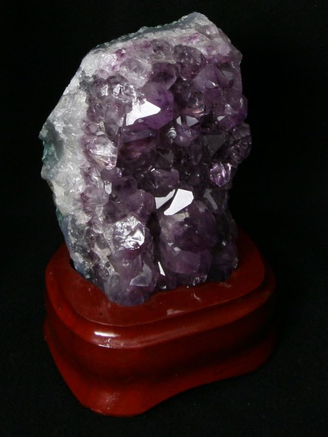
y
                  Ω
                                  P = (X, Y, Z)
 Π                 y∗

  t∗                     ∆x
                                                                                                                                                y∗

           ∆s
                                                                                                                                                     x

                                                                    s
                              f
                                                                                                                                                s∗ x

            (a) Light field geometry                                          (b) Pinhole view at (s∗ , t∗ ) and epipolar plane image Sy∗ ,t∗
Figure 3. Each camera location (s∗ , t∗ ) in the image plane Π yields a different pinhole view of the scene. By fixing a horizontal line of
constant y ∗ in the image plane and a constant camera coordinate t∗ , one obtains an epipolar plane image (EPI) in (x, s) coordinates. A
scene point P is projected onto a line in the EPI due to a linear correspondence between its s- and projected x-coordinate, see figure (a)
and equation (3).

through the field. We fix a horizontal line of constant y ∗                    as a reliability estimate ry∗ ,t∗ (x, s) ∈ [0, 1], which gives a
in the image plane and a constant camera coordinate t∗ , and                   measure of how reliable the local depth estimate is. Both
restrict the light field to an (x, s) -slice Σy∗ ,t∗ . The resulting           local estimates will used in subsequent sections to obtain a
map is called an epipolar plane image (EPI),                                   consistent depth map in a global optimization framework.
                                                                                  In order to obtain the local depth estimate, we need to
       Sy∗ ,t∗ : Σy∗ ,t∗ → R,
                                                                        (2)    estimate the direction of lines on the slice. This is done
                (x, s) 7→ Sy∗ ,t∗ (x, s) := L(x, y ∗ , s, t∗ ).                using the structure tensor J of the epipolar plane image S =
Let us consider the geometry of this map, figure 3. A point                    Sy∗ ,t∗ ,
P = (X, Y, Z) within the epipolar plane corresponding to
                                                                                         Gσ ∗ (Sx Sx ) Gσ ∗ (Sx Sy )          J     Jxy
the slice projects to a point in Ω depending on the chosen                       J=                                      = xx             . (4)
camera center in Π. If we vary s, the coordinate x changes                               Gσ ∗ (Sx Sy ) Gσ ∗ (Sy Sy )          Jxy Jyy
according to [5]                                                               Here, Gσ represents a Gaussian smoothing operator at an
                                  f
                        ∆x = − ∆s,                           (3)               outer scale σ and Sx ,Sy denote the gradient components
                                  Z                                            of S calculated on an inner scale ρ.
where f is the distance between the parallel planes1 .
    Interestingly, a point in 3D space is thus projected onto                     The direction of the local level lines can then be com-
a line in Σy∗ ,t∗ , where the slope of the line is related to its              puted via [3]
depth. This means that the intensity of the light field should
not change along such a line, provided that the objects in                                             J − Jxx          ∆x
                                                                                             ny∗ ,t∗ = yy           =        ,         (5)
the scene are Lambertian. Thus, if we want to estimate the                                               2Jxy           ∆s
depth for a ray Rx,y,s,t , we can try to find the slope of level
lines in the slices corresponding to the point. We now turn                    from which we derive the local depth estimate via equa-
to formulating this problem as a variational labeling prob-                    tion (3) as
                                                                                                                  ∆s
lem on the slice domains.                                                                            ly∗ ,t∗ = −f    .               (6)
                                                                                                                  ∆x
4. Local depth estimate on an EPI                                                 As the reliability measure we use the coherence of the
                                                                               structure tensor [3],
   We first consider how we can estimate the local direction
                                                                                                                            2 2
of a line at a point (x, s) for an epipolar plane image Sy∗ ,t∗ ,                                            (Jyy − Jxx ) + 4Jxy
where y ∗ and t∗ are fixed. The case of vertical slices is anal-                                ry∗ ,t∗ :=                        2      .           (7)
                                                                                                                  (Jxx + Jyy )
ogous. The goal of this step is to compute a local depth esti-
mate ly∗ ,t∗ (x, s) for each point of the slice domain, as well                    Using the local depth estimates dy∗ ,t∗ , dx∗ ,s∗ and relia-
    1 Note than to obtain this formula from figure 3(a), ∆x has to be cor-     bility estimates ry∗ ,t∗ , rx∗ ,s∗ for all the EPIs in horizontal
rected by the translation ∆s to account for the different local coordinate     and vertical direction, respectively, one can now proceed
systems of the views.                                                          to directly compute depth maps in a global optimization
λj λj
(a) Typical epipolar plane image Sy∗ ,t∗
ni ni
λi λi
(b) Noisy local depth estimate ly∗ ,t∗
(a) Allowed (b) Forbidden
Figure 4. Global labeling constraints on an EPI: if depth λi is less
than λj and corresponds to direction ni , then the transition from (c) Consistent depth estimate dy∗ ,t∗ after optimization
λi to λj is only allowed in a direction orthogonal to ni to not
Figure 5. With the consistent labeling scheme described in sec-
violate occlusing order.
tion 5, one can enforce global visibility constraints in order to im-
prove the depth estimates for each epipolar plane image. Brighter
framework, which is explained in section 6. However, it shades of green denote larger disparities and thus lines corre-
is possible to first enforce global visibility constraints sep- sponding to closer points.
arately on each of the EPIs. This step is computationally
expensive, but leads to the best results. We explain it in the Note that the penalty is weighted with the local reliability
next section. estimate, so that points at which the depth estimate is likely
inaccurate have less influence on the result.
5. Consistent EPI depth labeling The new slice labeling is then recovered by minimizing
the global energy functional
The computation of the local depth estimates using the
structure tensor only takes into account the immediate local N Z
X
structure of the light field. In truth, the depth values within E(u) = R(u) + ci ui d(x, s), (10)
a slice need to satisfy global visibility constraints across all i=1 Σy∗ ,t∗
cameras for the labeling to be consistent. In particular, a line
with is labeled with a certain depth cannot be interrupted by where u = (u1 , . . . , uN ) is the vector of indicator func-
a transition to a label corresponding to a greater depth, since tions. The difficult part is now to define the regularizer
this would violate occlusion ordering, figure 4. R(u) in a way that the labeling is globally consistent with
In this section, we show how we can obtain globally con- occlusion ordering.
sistent estimates for each slice, which take into account all We observe that the visibility constraints restrict the al-
views simultaneously. While this is a computationally very lowed relative positions of labeled regions.
expensive procedure, it yields the optimal results. How- If ni is the direction of the line corresponding to the
ever, for less complex light fields or if computation time is depth λi , then the transition from λi to a larger depth label
important, it can be omitted and one can proceed with the λj , j > i is only allowed to happen in a direction orthogonal
local estimates to section 6. to ni , figure 4. Otherwise, a closer point would be occluded
To satisfy the global visibility constraints on the slice by a point which is further away, which is impossible.
level, we compute for each slice a new labeling dy∗ ,t∗ which We enforce this occlusion ordering constraint by penal-
is close to the local estimate ly∗ ,t∗ , but satisfies the con- izing a transition from label λi to λj in direction ν with
straints. The desired labeling is a map
0 if i = j,
dy∗ ,t∗ : Σy∗ ,t∗ → {λ1 , . . . , λN } (8)
6 ±n⊥
∞ if i < j and ν = i ,
d(λi , λj , ν) :=
into a range of N discrete depth labels. We encode the
1 if i < j and ν = ±n⊥ i ,
d(λj , λi , ν)
minimization problem by using binary indicator functions otherwise.
ui : Σy∗ ,t∗ → {0, 1}, one for each of the N labels, with (11)
PN
the label uniqueness constraint that i=1 ui = 1. A region This problem fits into the minimization framework de-
where ui = 1 thus indicates a region of depth λi . scribed in [21], where the authors describe the construc-
We define local cost functions ci (x, s), which denote tion of a regularizer R to enforce the desired ordering con-
how expensive it is to assign the depth label λi at a straints. We use an implementation of their method to min-
point (x, s), as imize (10), and refer to their paper for more details. Note
that the optimization scheme in [21] only imposes soft con-
ci (x, s) := ry∗ ,t∗ (x, s) |λi − ly∗ ,t∗ (x, s)| . (9) straints, which means that there can still be some constraint
Source            Data set       Views        Resolution
                                                                            Blender [4]       Conehead      21 × 21       500 × 500
                                                                                              Buddha        21 × 21       768 × 768
                                                                                              Mona          41 × 41       512 × 512
                                                                            Gantry [20]       Truck         17 × 17       1280 × 960
                                                                                              Crystal       17 × 17       960 × 1280
                                                                            Plenoptic         Elephant           9×9      980 × 628
                                                                            camera [16]       Watch              9×9      980 × 628

                                                                          Figure 7. 4D Light field data sets used in our evaluation.
         (a) Central view                  (b) Ground truth
                                                                                                                   Dataset
                                                                            Method             ∆        Conehead    Mona      Buddha
                                                                            Stereo [7]         1          17.6       15.3      10.8
                                                                                               5          64.3       43.3      45.6
                                                                            Stereo [17]         1         34.5          9.5     19.1
                                                                                                5         94.6         56.8     91.7
                                                                            Local               1         21.5          8.1     26.4
                                                                            (section 4)         5         77.1         43.0     79.6
                                                                            Global              1         49.0         12.3     38.3
                                                                            (section 4 + 6)     5         98.7         74.3     95.9
      (c) Data term optimum         (d) After global optimization           Consistent          1         51.1         15.5     39.6
Figure 6. For a Lambertian light field with relatively simple geom-         (section 5 + 6)     5         98.9         80.1     97.1
etry, our global approach already yields an almost perfect depth
map. The expensive consistent estimate does not substantially im-     Figure 8. Comparison of estimated depth with ground truth for
prove the result anymore.                                             various approaches. The table shows the percentage of pixels for
                                                                      which the error is less than ∆ labels. Note that an error of one
violations left if the data term has a highly dominant prefer-        label corresponds to a relative depth error of only 0.2%, and the
ence for an inaccurate labeling.                                      count is with respect to all pixels in the image without regard to
    Figure 5 demonstrates the result of enforcing global con-         occluded regions.
sistency for a single EPI of a light field. While the lo-
cal depth estimate is noisy and of course does not satisfy            well, since computing the structure tensor entails an initial
any global constraints, the optimization yields a piecewise           smoothing of the input data. For this reason, we encourage
smooth estimate with sharp occlusion boundaries, which are            discontinuities of u to lie on edges of the original input im-
aligned in the proper direction corresponding to the closer           age by weighting the local smoothness with a measure of
depth label of the transition. In particular, consistent la-          the edge strength. We use
beling greatly improves robustness to non-Lambertian sur-
faces, since they typically lead only to a small subset of                                g(x, y) = 1 − rs∗ ,t∗ (x, y),                   (13)
outliers along an EPI-line.

6. Global Integration                                                    where rs∗ ,t∗ is the coherence measure for the structure
                                                                      tensor of the view image, defined similarly as in (7).
   After obtaining EPI depth estimates dy∗ ,t∗ and dx∗ ,s∗               In the data term, we want to encourage the solution to be
from the horizontal and vertical slices, respectively, we need        close to either dx∗ ,s∗ or dy∗ ,t∗ , while suppressing impulse
to integrate those estimates into a consistent single depth           noise. Also, the two estimates dx∗ ,s∗ and dy∗ ,t∗ shall be
map u : Ω → R for each view (s∗ , t∗ ). This is the objec-            weighted according to their reliability rx∗ ,s∗ and ry∗ ,t∗ . We
tive of the following section. We achieve our goal with a             achieve this by setting
globally optimal labeling scheme in the domain Ω, where
we minimize a functional of the form                                    ρ(u, x, y) := min(ry∗ ,t∗ (x, s∗ ) |u − dy∗ ,t∗ (x, s∗ )| ,
                                                                                                                                          (14)
                                                                                              rx∗ ,s∗ (y, t∗ ) |u − dx∗ ,s∗ (y, t∗ )|).
                   Z
          E(u) =       g |Du| + ρ(u, x, y) d(x, y).       (12)
                      Ω
                                                                      We compute globally optimal solutions to the func-
In figure 6, we can see that the per-slice estimates are              tional (12) using the technique of functional lifting de-
still noisy. Furthermore, edges are not yet localized very            scribed in [17].
(a) Center view                  (b) Stereo [17]                (c) Ours (global)              (d) Ours (consistent)
Figure 9. The synthetic light field “Mona” with some specularities and complex geometry is surprisingly difficult for depth reconstruction.
Here, the consistent estimate yields a substantial improvement over global integration only, which already outperforms other methods.

     (a) Stereo [7], intensities rescaled     (b) Ours (local)                 (c) Stereo [17]                (d) Ours (global)
Figure 10. With our methods, we can perform stable depth reconstruction in the synthetic light field “Buddha”. The global stereo algorithm
also achieves a satisfactory result, but has obvious difficulties on the specular statue and metal beam. See figure 1 for center view and
result from our consistent estimation, which yields small, but visible and measurable improvements.

7. Experiments                                                          gration. We found that σ = τ = 0.8 works well in most
                                                                        examples, and results are very robust to parameter varia-
   In this section, we verify the robustness and quality of             tions.
depth estimates based on orientations in the epipolar plane                Comparison of local estimates. Local estimation of
image, and compare our results to stereo matching ap-                   depth for a single view performs at interactive frame rates.
proaches. For this, we perform depth reconstruction on a                In table 8, one can see that our local data term on its own is
number of data sets from various sources, see figure 7. The             often already more precise than a stereo approach [7]. This
synthetic data sets and ground truth created with Blender               shows that the Lumigraph is a highly efficient data structure
will be provided on our webpage for future evaluations.                 for depth estimation tasks, since with low amount of effort
   With our experiments we show that the light field                    we obtain dense depth maps and for the most part bypass
paradigm provides better results if compared to stereo meth-            the occlusion problem by accumulating information from
ods with comparable computational effort. In the first step,            many surrounding views. Note that in this step, the local es-
we compare our data term or local estimation using our                  timate performs depth estimation at floating point precision,
structure tensor segmentation (section 4) to a local stereo             which is the main cause of the high accuracy compared to
approach [7]. In the second step, we compare the results of             the stereo matching method which is much more quantized,
our global optimization (section 4 and 6) to a stereo match-            see figure 10.
ing approach within the same global optimization frame-                    Comparison of global estimates. Integrating the local
work [17]. Finally, we demonstrate the potential of the very            depth estimates into a globally optimized depth map takes
accurate but also time-consuming consistent approach (sec-              about 2-10 minutes per view depending on resolution and
tion 5 and 6).                                                          number of depth labels. Total computation times are com-
   Table 8 shows quantitative results of all the experiments            parable for both stereo matching as well as our novel tech-
with available ground truth data. For all methods, param-               nique based on structure tensor computation. Figures 9 to11
eters were tuned to achieve optimum results. In our case,               show visual comparisons of our global optimization to an
the dominant parameters are the scale parameters σ, τ for               approach which uses stereo matching [17], but which opti-
the structure tensor and a smoothing factor for global inte-            mizes the same global functional (12) with a different data
(a) Center view                         (b) Stereo reconstruction [17]                  (c) Our method (global)
Figure 11. Exploiting the structure of 4D light fields allows stable depth reconstruction even for very difficult scenes with reflective and
specular surfaces, where methods based on stereo matching tend to fail. Note that the stereo result is already overly smoothed in some
regions, while there is still a lot of noise left in the specular areas. Data sets “Truck” and “Crystal” from Stanford light field archive,
17 × 17 images at resolution 1280 × 960, runtime 15 minutes for both methods with 128 depth labels on an nVidia Fermi GPU.

term. The numerical results in table 8 once again demon-                  8. Conclusions
strate the superiority of the light field structure for depth
estimation.                                                                   We have introduced a novel idea for robust depth estima-
                                                                          tion from 4D light field data in a variational framework. We
    Consistent labeling. The full accuracy of the depth eval-             locally estimate depth using dominant directions on epipo-
uation based on light fields is only achievable if we make                lar plane images, which are obtained using the structure ten-
use of the entire information provided in the EPI represen-               sor. The local estimates are integrated into global depth
tation. For this, we need to impose the global occlusion                  maps with a globally optimal state-of-the-art convex opti-
ordering constraints described in section 5, which takes sev-             mization method. At greater computational cost, it is also
eral hours to compute for all EPIs, but computes data for all             possible to recover depth estimates which satisfy global
views in the light field simultaneously. The visual and nu-               visibility constraints. This can be done by labeling each
merical improvements are shown in figures 9 and 10 as well                epipolar plane image separately and imposing spatial layout
as table 8.                                                               constraints using a recent continuous optimization method
    Plenoptic camera images. We also experimentally                       based on convex relaxation.
demonstrate that our depth reconstruction technique works                     We achieve state-of-the-art results, whose accuracy sig-
with images from a Raytrix plenoptic camera [16] and                      nificantly surpasses that of traditional stereo-based meth-
yields results which are superior to the reference algorithm              ods. Furthermore, on data sets from various sources includ-
provided by the manufacturer, figure 12. Note that in order               ing plenoptic cameras, we demonstrated that by taking into
to run our algorithm on this type of images, we first need to             account the special structure of 4D light fields one can ro-
perform a conversion to a Lumigraph [23].                                 bustly estimate depth for non-Lambertian surfaces.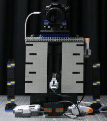
(a) Center view                    (b) Reference algorithm by manufacturer                 (c) Our result (global)
Figure 12. Depth estimates from lightfields acquired with the Raytrix plenoptic camera, which compare our method to a reference algorithm
provided by the camera manufacturer on difficult real-world scenes with reflective metal objects. Our result clearly provides more details
in the reconstruction.

References                                                              [12] M. Levoy and P. Hanrahan. Light field rendering. In Proc.
                                                                             ACM SIGGRAPH, pages 31–42, 1996. 2
 [1] E. Adelson and J. Bergen. The plenoptic function and the           [13] M. Matoušek, T. Werner, and V. Hlavác. Accurate corre-
     elements of early vision. Computational models of visual                spondences from epipolar plane images. In Proc. Computer
     processing, 1, 1991. 2                                                  Vision Winter Workshop, pages 181–189, 2001. 2
 [2] J. Berent and P. Dragotti. Segmentation of epipolar-plane im-      [14] L. McMillan and G. Bishop. Plenoptic modeling: An image-
     age volumes with occlusion and disocclusion competition. In             based rendering system. In Proc. ACM SIGGRAPH, pages
     IEEE 8th Workshop on Multimedia Signal Processing, pages                39–46, 1995. 1, 2
     182–185, 2006. 2                                                   [15] R. Ng, M. Levoy, M. Brédif, G. Duval, M. Horowitz, and
 [3] J. Bigün and G. Granlund. Optimal orientation detection of             P. Hanrahan. Light field photography with a hand-held
     linear symmetry. In Proc. ICCV, pages 433–438, 1987. 3                  plenoptic camera. Technical Report CSTR 2005-02, Stan-
 [4] Blender Foundation. www.blender.org. 5                                  ford University, 2005. 1
 [5] R. Bolles, H. Baker, and D. Marimont. Epipolar-plane image         [16] C. Perwass and L. Wietzke. The next generation of photog-
     analysis: An approach to determining structure from motion.             raphy, 2010. www.raytrix.de. 1, 2, 5, 7
     International Journal of Computer Vision, 1(1):7–55, 1987.         [17] T. Pock, D. Cremers, H. Bischof, and A. Chambolle. Global
     2, 3                                                                    solutions of variational models with convex regularization.
 [6] A. Criminisi, S. Kang, R. Swaminathan, R. Szeliski, and                 SIAM Journal on Imaging Sciences, 2010. 2, 5, 6, 7
     P. Anandan. Extracting layers and analyzing their specular         [18] S. Seitz and C. Dyer. Physically-valid view synthesis by im-
     properties using epipolar-plane-image analysis. Computer                age interpolation. In Proc. IEEE Workshop on Representa-
     vision and image understanding, 97(1):51–85, 2005. 1, 2                 tion of visual scenes, pages 18–25, 1995. 1
 [7] A. Geiger, M. Roser, and R. Urtasun. Efficient large-scale         [19] H. Shum, S. Chan, and S. Kang. Image-based rendering.
     stereo matching. In Proc. ACCV, 2010. 5, 6                              Springer-Verlag New York Inc, 2007. 2
 [8] T. Georgiev and A. Lumsdaine. Focused plenoptic camera             [20] The      (New)       Stanford      Light     Field     Archive.
     and rendering. Journal of Electronic Imaging, 19:021106,                http://lightfield.stanford.edu. 1, 2, 5
     2010. 1                                                            [21] E. Strekalovskiy and D. Cremers. Generalized ordering con-
 [9] S. Gortler, R. Grzeszczuk, R. Szeliski, and M. Cohen. The               straints for multilabel optimization. In Proc. International
     Lumigraph. In Proc. ACM SIGGRAPH, pages 43–54, 1996.                    Conference on Computer Vision, 2011. 2, 4
     2                                                                  [22] V. Vaish, B. Wilburn, N. Joshi, and M. Levoy. Using plane +
[10] A. Katayama, K. Tanaka, T. Oshino, and H. Tamura.                       parallax for calibrating dense camera arrays. In Proc. CVPR,
     Viewpoint-dependent stereoscopic display using interpola-               2004. 1
     tion of multiviewpoint images. In Proceedings of SPIE, vol-        [23] S. Wanner, J. Fehr, and B. Jähne. Generating EPI represen-
     ume 2409, page 11, 1995. 1                                              tations of 4D light fields with a single lens focused plenoptic
                                                                             camera. Advances in Visual Computing, pages 90–101, 2011.
[11] M. Levoy. Light fields and computational imaging. Com-
                                                                             7
     puter, 39(8):46–55, 2006. 1
You can also read