Future Developments in Charged Particle Therapy: Improving Beam Delivery for Efficiency and Efficacy - arXiv
←
→
Page content transcription
If your browser does not render page correctly, please read the page content below
Future Developments in Charged Particle Therapy:
                                                  Improving Beam Delivery for Efficiency and Efficacy
                                                                        Jacinta Yap1* , Andrea De Franco2 , and Suzie Sheehy1
                                                            1
                                                             School of Physics, University of Melbourne, Melbourne, VIC, Australia.
                                                     2
                                                         National Institute for Quantum and Radiological Science and Technology (QST),
arXiv:2109.10084v1 [physics.med-ph] 21 Sep 2021

                                                                                 Rokkasho-mura, Aomori, Japan.
                                                                          *
                                                                              Corresponding author. Email: jacinta.yap@unimelb.edu.au

                                                                                                    Abstract

                                                               The physical and clinical benefits of charged particle therapy (CPT) are well recog-
                                                          nised and recent developments have led to the rapid emergence of facilities, resulting in
                                                          wider adoption worldwide. Nonetheless, the availability of CPT and complete exploitation
                                                          of dosimetric advantages are still limited by high facility costs and technological challenges.
                                                          There are extensive ongoing efforts to improve upon these, which will lead to greater accessi-
                                                          bility, superior delivery, and therefore better treatment outcomes. The issue of cost however
                                                          still remains a primary hurdle as the utility of CPT is largely driven by the affordability,
                                                          complexity and performance of current technology. Several of these aspects can be addressed
                                                          by developments to the beam delivery system (BDS) which determine the overall shaping
                                                          and timing capabilities to provide high quality treatments. Modern delivery techniques are
                                                          necessary but are limited by extended treatment times. The energy layer switching time
                                                          (ELST) is a limiting constraint of the BDS and a determinant of the beam delivery time
                                                          (BDT), along with the accelerator and other factors. This review evaluates the delivery
                                                          process in detail, presenting the limitations and developments for the BDS and related ac-
                                                          celerator technology, toward decreasing the BDT. As extended BDT impacts motion and
                                                          has dosimetric implications for treatment, we discuss avenues to minimise the ELST and
                                                          overview the clinical benefits and feasibility of a large energy acceptance BDS. These de-
                                                          velopments support the possibility of delivering advanced methodologies such as volumetric
                                                          rescanning, FLASH and arc therapy and can further reduce costs given a faster delivery for
                                                          a greater range of treatment indications. Further work to realise multi-ion, image guided
                                                          and adaptive therapies is also discussed. In this review we examine how increased treatment
                                                          efficiency and efficacy could be achieved with an improved BDS and how this could lead to
                                                          faster and higher quality treatments for the future of CPT.

                                                  Keywords:

                                                      particle therapy, beam delivery, accelerators, large energy acceptance, energy layer switching time,
                                                  rescanning, FLASH, Arc therapy

                                                                                                        1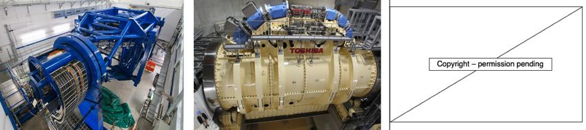
1    Introduction
Access to charged particle therapy is growing rapidly worldwide. As a therapeutic modality CPT is now
well established, where proton beam therapy (PBT) is the most common type. Growth in the number
of facilities has been bolstered by developments in accelerators and related technologies, beam delivery
methods, verification tools, and increased clinical experience. Where available, PBT is often standard
practice, particularly for paediatric cases and specific tumour types (ocular, head and neck tumours [1]).
CPT has an important prospective role in reducing the growing cancer burden on a global scale, and its
impact could be significant [2] however, its full potential is yet to be realised. Overcoming this requires
improvements in two key areas: improving efficacy and decreasing cost.

     CPT offers benefits over and above regular radiotherapy (RT) for palliative or curative treatments,
offering not just physical dose escalation but also biological advantage. Yet in terms of efficacy, we cannot
capitalise fully on increased radiobiological effectiveness of charged particles at present, primarily due
to limitations in knowledge [3]. For this reason, existing programmes of research are investigating the
underlying mechanisms of CPT in terms of fundamental chemical, biological and cellular processes [4–9]
to try to understand the roles of these processes in determining clinical outcomes [10–12]. Nonetheless,
the superior physical properties of charged particles are evident as the characteristic ‘Bragg Peak ’ (BP)
enables a precise dose distribution and an improved therapeutic window.

    The second reason we cannot yet fully exploit the efficacy of CPT is due to technological limitations.
Advanced techniques and technological improvements for CPT seek to deliver higher quality treatments
with increased conformity as these translate to long-term benefits. However some of these improvements
would increase, rather than decrease, the cost of the treatment.

    In terms of cost (or efficiency) the gap between conventional X-ray photon RT (XRT) and CPT still
exists due to the many challenges to be addressed: affordability, complexity and limitations with current
technology all restrict the utility of CPT. Although availability has surged in recent years as several
vendors offer competitive and commercial turn-key solutions, high capital and operational costs are still
a primary issue. Many potential areas of improvement have been well identified [13–20]. In general,
the potential for cost reduction can be considered by decreasing the facility and machine size, opera-
tional complexities, treatment times, increasing the treatment workflow efficiency and hence throughput.

    However, just making the treatment cheap and widespread is not enough. Both efficiency and effi-
cacy need to be improved, in other words, even in an ideal world of low-cost and widespread availability
of facilities, the maximum possible clinical benefit of CPT will only be achievable if existing technical
limitations are overcome. While there are many factors which govern the overall cost and efficacy of
treatment: one key underlying aspect is the beam delivery. Complimentary to the accelerator complex,
the beam delivery system is an essential piece in the treatment workflow which contributes significantly
to the overall treatment time, and which will form the primary focus of this review.

    At present, the majority of CPT treatments use active pencil beam scanning (PBS), involving the
intricate delivery of several thousand overlapping narrow beams which results in highly conformal dose
distributions. Most clinical indications are treated with PBS however an unavoidable and consequential
issue is the lengthy beam delivery time. During treatment the beam is scanned across the (potentially
large) target site, and the accelerator complex, control system and diagnostic instruments need to adjust.
A key bottleneck in this process is the energy layer switching time.

                                                     2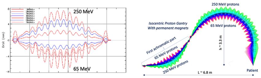
The slow ELST is due to technical constraints and is a prevalent issue: it is the critical component
which accounts for the majority of the BDT [21, 22]. The beam moves relatively quickly across the
tumour transversely, but it takes much longer to switch the beam in depth. This extends the beam-on
time and long overall irradiation times can increase dose uncertainties. This is a key problem for cases
where the tumour site itself may also move, for example, interplay effects are unavoidable during lung
treatments as caused by respiratory motion. Although different motion management approaches such as
gating, rescanning and tracking can be performed, the clinical implications reduce the utility of CPT,
especially in particular indications [11]. Moreover, as the high dose BP region is a motivation for using
CPT, sensitivity to changes in range are especially important – and for heavy ions this is even greater –
which impairs benefits attained from the physical and radiobiological advantages [23, 24]. In other words,
the beam delivery impacts both efficiency (cost) and efficacy, and is thus a crucial aspect to investigate
for the future of CPT.

    Of course, there are many aspects of CPT, both technological and systems-based which could im-
prove efficacy and cost in future: the scope of this review is to look at the technology pertaining to the
BDS, broadly covering those aspects of the system which impact the dose delivery process and treat-
ment time1 . An improved BDS could lead to better treatment efficiency and efficacy, both of which are
necessary for advanced delivery methodologies.

    There are several limitations and central issues surrounding existing BDS capabilities which need to
be addressed to improve the delivery of CPT in future. In the near term, can we improve the capabilities
of the BDS to better deliver CPT? Can we decrease the BDT? What are the current constraints and
where are improvements needed? How does this translate to the clinic? In the longer term, what does
the future of CPT delivery look like? How will new treatment paradigms such as FLASH or multi-ion
therapy be limited by BDS technology?

    We review the limitations and developments needed for the BDS and related accelerator technology
with the outlook of decreasing the BDT. The clinical feasibility, impact on the delivery process and
potential benefits of different approaches are examined, with a focus on the perspective of minimising
the ELST, its contribution to the BDT and its implication for treatment.

2       Beam Delivery
The beam produced by the accelerator must be shaped and modified to deliver dose to the target site
matching the requirements of the treatment plan. This requires changing the distribution of the spatial
(lateral) and energy (longitudinal) spread and also often the time structure, i.e. beam modification in
four-dimensions is required. These can be tuned to an extent by the accelerator complex and beam
transport lines (BTL). In this review we define the BDS as the components after the accelerator which
determine how the beam is shaped, transported and ultimately delivered to the patient for treatment.
This encompasses the BTL, diagnostic instrumentation, energy selection systems, treatment line (gantry
or fixed delivery line) and treatment head. For brevity, we focus on the BTL, treatment line and delivery
system for PBS (Figure 1).

   Treatments can take anywhere from a few minutes to more than half an hour, depending on the
tumour type and complexity of the plan. The overall treatment time is determined by the BDT, addi-
    1
     Existing recommendations and requirements for technological improvements have been primarily focused on
PBT, which precede developments for CPT with heavier ions due to greater clinical experience. We include many
references to PBT for readers to explore these where relevant.

                                                     3
Figure 1: Illustration overviewing the main components in a CPT treatment facility. The BDS
is shown to include the BTL (beam instrumentation and devices which may alter the energy or
shape of the beam) and treatment line (fixed line or here, a gantry).

tional activities including patient setup (immobilisation, imaging, unload etc.) and equipment related
checks (couch positioning, beam checks, readying beam devices etc.). The BDT consists of the actual
irradiation ‘beam-on’ time and the ‘beam-off ’ time, spent requesting and waiting on the beam after ad-
justments or between fields. A quantitative analysis of PBT treatments by Suzuki et al. [25] reported
that approximately 80% of treatment time was spent on these additional activities with the remaining
20% contributed by the BDT. Total treatment time is shown to increase quadratically with the number
of fields, with complex cases requiring the same amount of time to carry out patient-related activities but
accruing larger contributions from equipment checks and BDT. Reductions in these latter aspects have
more potential to improve the efficiency as patient-related process times can vary widely, are circum-
stantial, depend on the physical and clinical condition of the patient and cannot necessarily be improved
with technology. Furthermore, shorter treatment times are preferred not just for cost but also due to
difficulty of immobilisation and set-up of patients for 30 minutes or longer. As discussed by Nystrom &
Paganetti et al. [13], a faster BDT can result in a significant gain in treatment efficiency, particularly for
multi-room facilities with high waiting times. Evidently, any increase in treatment efficiency is valuable.

    Decreasing BDT is complex as facilities are not standardised, and neither are prescribed treatment
plans. The BDS, accelerator and other systems vary at each facility and the delivery efficiency depends
on numerous technology-related factors. Facilities have different equipment vendors, numbers of rooms,
delivery systems etc. and often adopt different processes: these characteristics all influence the delivery
procedures implemented [26]. Meanwhile the treatment plan calculates the number of spots and layers
to deliver the required dose distribution to the target volume. Nystrom & Paganetti et al. [13] state
the three main components which constitute the delivery time for a treatment field: time to irradiate
a spot, time to move between spots and the time to change beam energy. Speeding up any of these
components can shorten BDT however they are not independent variables. Delivering a faster treatment
is not straightforward; it is not solely dependent on the capabilities of the BDS itself but is a multi-
faceted problem. All the contributing factors and their corresponding time budgets can be examined to
assess their impact on dose delivery and the BDT, illustrated in Figure 2.

                                                      4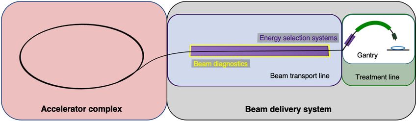
Figure 2: Overview of PBS beam delivery and different motion mitigation strategies. Breakdown
of contributions from the beam production, beam transport and delivery processes to BDT.

                                             5
2.1 Pencil Beam Scanning
The objective of the BDS is to deliver the beam with the required parameters prescribed by the treatment
plan. The planned dose distribution determines the requested parameters and thus system configuration
(i.e. together with the source, accelerator, low, medium and high energy beam transport systems). The
requested specifications include the beam energies, size at isocentre, intensities and delivery channels:
each different configuration can total to thousands of available beam combinations [27]. This results
in the delivery of multiple beams which produce a 3D dose distribution and as previously mentioned,
the entire process can to amount to long treatment times. For PBS delivery, the beam is magnetically
deflected across the tumour in the transverse plane across one layer or an iso-energy slice (IES), then
adjusted longitudinally to a shorter depth (typically a decrease in proton range of 5 mm in water) and
repeated (Figure 3).
Figure 3: Active PBS delivery. The BDS delivers a conformal dose distribution to the treatment
volume by scanning the beam along a calculated path in the transverse plane. The beam energy
is then adjusted to change the depth, typically lower in energy, switching to a proximal IES
where the subsequent layers are scanned.
Different scanning techniques (spot, raster and line/continuous) may be used with optimisation
methods to deliver the beam and irradiate each layer. The dose is painted such that the accumulation
of the distribution in both planes results in sufficient coverage of the tumour volume (Figure 4).
Figure 4: Spot, raster and continuous line scanning patterns for PBS delivery. Spots and solid
lines indicate beam-on irradiation and dashed lines indicate movement with beam-off.
If we consider only the beam delivery process, this can be approximated to include the [T1 ] transverse
scanning, [T2 ] energy adjustment and [T3 ] systematic dead times (Figure 5).
6Figure 5: Major BDS components and corresponding factors which contribute to BDT.
2.1.1 BDT time components
Each IES irradiation engages multiple aspects of the BDS, combining to the total BDT. The time com-
ponents of a typical treatment can be examined by breaking down the PBS delivery process. As a
general example, the BDT can be approximated by summing the different contributions by estimating
time allocations associated with each of the 3 factors.
[T1A ] the staying or ‘dwell ’ time at a position can be down to 0.1 ms and the [T1B ] transition time
to the next position, 0.03 ms [28]. For line scanning, [T2A ] could be 5 ms for a line and [T2B ] 5 ms to
move to the next line [29]. For an IES, it could take 10’s ms altogether for raster scanning [30]. [T1 ]
Irradiation time for a single IES depends on the size of the distribution but needs at least ∼100 ms.
[T2 ] ranges from 80 ms to a few seconds [15], corresponding to faster dynamic modulation with
cyclotrons and synchrocyclotrons, or slower direct energy adjustments with synchrotrons. The fastest
reported ELSTs are listed in Table 1.
[T3 ] ionisation chamber measurement times average ∼0.1 ms [13, 27]. ACS and diagnostic safety
checks ensure correct beam parameters (spot size, position, intensity etc.). As reported by Schoemers et
al. [31] measurement times are a bottom line limit across the BDS and similarly for continuous scanning,
the lower bound is determined by the instrumentation speed [20]; at least 1 ms is required.
These estimations are provided (within applicable orders of magnitude) as based on broadly reported
values and for context, can be expressed simply by:
BDT = (N )T1 + (N − 1)T2 + (N )T3 .
Where N is the number of IES. For example, a BDT estimate for a simple case with fast timing budgets
and a once, single directional irradiation, for 30 IES: 30×[T1 = 150 ms] + 29×[T2 = 500 ms] + 30×[T3
= 2 ms] = 19 s.
7The BDT is a function of the irradiation sequencing and indeed, a larger tumour volume or higher
number of IES recruits more of these actions [T1–3 ], amounting to a longer BDT. It is noted that the
actual beam-on irradiation time [T1A ] is very short compared to the beam-off [T2 ] and dead times
[T3 ]; often the total dead time exceeds the irradiation time. Independently, the irradiation time is es-
sentially determined by the intensity of the beam produced by the accelerator [15, 31]. As a standard
(PBT) clinical minimum, most facilities have the capability of delivering dose rates of 2 Gy/min to a
1 L volume, 10–20 cm deep [32]. This equates to beam currents of 100’s nA, varying for accelerator
type. However, even at facilities which are able to achieve higher dose rates, there are practical limi-
tations with operation at higher intensities. These depend on machine characteristics as well as safety
regulations and instrumentation constraints, as experienced with attempts to reach FLASH rates [33, 34].
Alternatively, the transverse motion of the beam can be sped up by using continuous scanning
methods and with faster dipole magnets. As discussed by Flanz & Paganetti et al. [13] scanning dipoles
from 3–100 Hz are used clinically but capabilities also depend on their size, distance from the patient as
well as inductance and power supply considerations. Furthermore, speeds are restricted by the viability
of currently available beam instrumentation tools to accurately measure and rapidly record dose rates.
2.2 Energy Layer Switching Time
Decreasing the time delays imposed by [T2 ] changing energy between IES appears to be the more chal-
lenging issue. Similarly, it is not just a singular aspect of the delivery process but is governed by the
accelerator and significantly, the BDS. The ELST across facilities ranges widely and can be up to an order
of magnitude longer than the time it takes to scan across an IES. If we consider the breakdown of time
components again (Section 2.1.1) but this time applying a fast ELST (100 ms) instead for comparison:
30×[T1 = 150 ms] + 29×[T2 = 100 ms] + 30×[T3 = 2 ms] = 6.9 s.
Evidently, this results in a much shorter BDT. The ELST appears to be the limiting constraint;
particularly for cases with many layers which may also need rescanning, there is an accumulation of time
saved at each step. The increasing penalty for longer ELSTs on BDT is illustrated in Figure 6.
Figure 6: Total BDTs estimated for a range of applicable clinical ELSTs (T2 ) with fixed times
for the transverse scan (T2 ) and system dead times (T3 ), for each IES. Timings are based on
previously reported information, where values were made available. For all 30 IES, T1 = 4.5 s
and T3 = 0.06 s.
8Several studies have been performed which examine the time components quantitatively and evaluate
the impact of the ELST on BDT, as a means to improve treatment delivery efficiency. Shen et al. [21]
carried out a detailed analysis to model the BDT at a synchrotron PBT facility based on operational
parameters including the ELST, average scanning speeds, spill rate, charge and extraction time, magnet
preparation and verification time. These contributions were similarly reduced to 3 time components (i.e.
[T1A ], [T1B ] and [T2 ]) where the average ELST across the energy range and scanning speeds in x and
y were reported as 1.91 s, 5.9 m/s and 19.3 m/s, respectively. Values determined by the model were
compared with log files from a large range of delivered patient treatments to calculate the contributions
to BDT accurately. The ELST was identified as the most dominant contributor to BDT at 71%; reducing
this time would greatly improve beam utility during delivery.
All components of the treatment process were also comprehensively analysed by Suzuki et al. [25] to
evaluate the use factor and efficiency of beam delivery parameters for different disease sites. Although
there are numerous factors, the BDS largely governs treatment efficiency which is asserted as the most
important factor in PBT as it is directly related to utility and availability: for facilities which operate a
busy schedule, a 1 min reduction in BDT for a single field could result in the equivalent of treating 10
more (prostate) patients a day. This can also lower costs as treatment costs scale with the total time
spent by the patient in the treatment room [13].
Increasing throughput is an important consideration to improve the availability of CPT. A sensitivity
analysis of daily throughput capacity – and therefore efficiency of PBS treatments – was subsequently
performed at the same facility by Suzuki et al. [22]. Several parameters in the treatment process were
similarly studied; the BDT was reduced to the sum of the ELST and spot delivery time as a function
of the treatment volume, dependent on the disease site. The ELST was reported as 2.1 s and accounted
for 70–90% of the BDT for the majority of tumour volumes (3 cm depths)
plates (lexan/polycarbonate)
(carbon wedges) and range shifters (3 Limitations and avenues for improvements
3.1 Accelerators
The timing structure of delivered beams varies significantly between different types of accelerators, as
they have different technological and safety limitations. In this section we present the main opera-
tional patterns and optimisation challenges for synchrotrons, cyclotrons, synchrocyclotrons and other
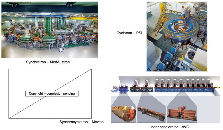
accelerators that may soon be available for PBT or CPT facilities (Figure 7).
Figure 7: Synchrotron at the MedAustron facility [42] and COMET cyclotron (for PBT) at
PSI [43]. Gantry-mounted Mevion S250i synchrocyclotron [44]. Depiction of the AVO LIGHT
LINAC with the radiofrequency quadrupole, side coupled drift tube linac and coupled cavity
linac sections highlighted [45].
3.1.1 Synchrotrons
The most common operation pattern for synchrotrons starts by injecting a beam pulse from a radiofre-
quency quadrupole (RFQ) and linear accelerator (LINAC) at up to ∼5 MeV/u (order of 10–100 µs)
of ∼ 1011 protons (or ∼ 109 carbon ions) into the main synchrotron ring. The beam is accelerated in
∼1 s to the desired energy, then slowly but continuously extracted and transported to the irradiation
room to treat a specific treatment slice. While extraction processes are typically capable to deliver the
entire accumulated charge in 1 L) in combination with hypofractionation requires more than one injection for some of the energy
layer. The total time required to change energy (or refill the main ring) is then of the order of ∼2–4 s.
10Two significant technological solutions have been implemented so far which drastically reduce the
time required to change energy/refill the ring. The first is to reduce the time required to wash the
magnets to a few hundreds of ms by employing an active regulation of the magnet power supply output,
based on live measurement of the magnetic field [46, 47]. The technology necessary for active regulation
of quadrupoles or sextupoles has not been implemented in clinical machines yet and therefore they still
require washing, taking ∼100’s ms. The total time to change energy/refill is then reduced to ∼1–2 s.
The second technique is called multiple energy extraction (MEE) operation (or extended flattop
operation) and aims to reducing only (but drastically) the time required to change energy. In MEE
[48] the beam can be extracted across several energy levels in a single spill; this enables the delivery of
successive IES without needing to wait for re-/acceleration. The unused part of the beam circulating
after completion of a slice is re-accelerated (or decelerated) instead of being dumped in preparation for
a re-injection. Although the process is not completely lossless, it requires only roughly ∼100 ms [38, 49]
to change beam energy. Younkin et al. [50] performed a study to quantify BDT savings with MEE
implemented at a synchrotron PBT facility, finding an average of 35% reduction in BDT. The ELST
was reduced by around 90% from a typical value of ∼2 s to 200 ms with MEE. Additional savings could
also be achieved by improving charge, extraction limits and charge recapture rates: these depend on
the performance and limits of the synchrotron. Note that in this scenario the re-injection times are not
improved from the typical operation mode.
The extraction mechanism most often used in synchrotron ion beam therapy facilities is based around
a slow resonant mechanism which is usually driven by a transverse excitation (RF knockout (RF-KO)
[51, 52]) or a longitudinally slowly induced energy change (Betatron magnet [47, 53, 54]). The former
technique can keep the beam bunched throughout the extraction process, making re-acceleration (or
deceleration) a delicate but feasible process. The latter requires the de-bunching of the beam, which
makes further re-acceleration (or deceleration) theoretically possible (RF front acceleration), but ex-
tremely challenging, loss prone and potentially time consuming. Facilities not originally designed for
MEE operation exhibit the trend to implement RF-KO first rather than attempting other retro-fitted
techniques [55–57]. The direction of energy change is typically fixed (e.g. always increases or decreases),
because an up-down energy scanning would violate the reproducibility of the main ring magnetic field
due to hysteresis effects. A magnetic field active regulation control would be necessary for this feature,
but it has not been implemented for quadrupole and sextupoles magnets to date.
Alternative extraction techniques which are compatible with bunched beams are based on optics
changes often used in larger synchrotrons for non-clinical applications [58]. These could be applied in
the future but so far promise limited advantages for small machines dedicated to therapy. The limited
benefits offered by MEE operations for hypofractionated treatments of large lesions can be overcome
by increasing the particle filling of the ring. Although the most pursued R&D is a reduction of the
facility footprint, LINACs capable of accelerating orders of magnitude larger currents of protons and
light ions to ∼10 MeV exist or are being developed [59–61]. An extreme example is LIPAc [62] which
has already demonstrated the acceleration of 5 MeV, 125 mA deuteron beam; this is ∼50 times more
than the currents typically injected in synchrotrons for therapy.
Although it is not the focus of this work, it is worth mentioning that often synchrotrons are chosen
by therapy centres also for their capability and ease of delivering multiple particle species (proton, He, C,
O, etc.). Assuming multiple ion sources are used for each species. The time required to switch particle
species is driven by the change and stabilisation of the field in the injector’s and low/medium energy
11beam transportation’s magnets. In some tests at NIRS-QST this was chosen to be ∼20 s [63] but could
potentially be reduced to only few seconds with dedicated design and development of the source, injector
and overall control system [64].
3.1.2 Cyclotrons & Synchrocyclotrons
The most common choice for proton therapy is the cyclotron (mostly isochronous cyclotrons), which
always accelerate protons to a single (maximum) energy. The beam is typically available as a continuous
wave (CW) beam with a micro-bunch structure of 100’s MHz. As the extraction energy is fixed, the
energy can only be changed by inserting material in the beamline to degrade the energy. This method
produces large losses especially when selecting energy at the lower end of the spectrum (∼90% of the
beam can be lost), creating a radioactive hot spot in the location of the system. The downstream beam
has a very large distribution of energies, not suitable for precise 3D conformal dose delivery. Therefore,
an energy selection system (ESS) usually follows the energy degrader. The ESS consists of several de-
vices (degraders i.e. carbon or graphite wedges, collimators, slits, magnets, diagnostics etc.) which are
necessary to modify the beam to have the correct parameters for treatment. The transmission, quality
and distribution of the beam is affected by interactions with objects in the beam path (the increase in
distal penumbra from the energy spread can be up to 10 mm) [15]. The optics is designed to create a
section with a large dispersion, where slits are inserted to trim the beam and reduce the energy spread.
This also has implications for the gantry, discussed later.
Compared to synchrotrons, the time taken to mechanically insert the beam modifying devices is
relatively quick (∼10’s ms) for small energy adjustments. The use of actuated static wedges with time
compensation and fast deflecting magnets (range adaptation) is reported to be the fastest method, chang-
ing energies in less than 20 ms [65]. At PSI the wedge positioning takes 50 ms, as reported by Pedroni et
al. [36] and the fastest energy modulation times are achievable on gantry 2 at 80 ms. Delays are caused
by stabilisation of the dipole magnets in the beam transport line and gantry. The direction of the energy
change is not limited by the accelerator, but the reproducibility of the magnetic field in the ESS. The
accelerator itself does not limit the direction swap of the energy change, which can change up and down
in any sequence. The hysteresis of ferromagnetic components in the beam transport typically restricts
fast energy change to one direction only, with a magnet wash required before each direction swap. The
BDS magnets must be ramped to accommodate different energies and to preserve the beam position at
isocentre: it is the time taken to vary and reset the magnetic fields in the BDS which determine the
ELST time. This also holds true for synchrotron facilities however the extraction times far surpass these
at present. Although designs for cyclotrons dedicated to particle therapy with He or C exist [66, 67], no
facility has so far been developed yet.
Finally, we consider superconducting synchrocyclotrons, which produce a pulsed beam as they are
not isochronous. This type of accelerator can bypass the limiting constraints of the BDS magnets as
– at least for protons – it can be made into a single room system. The accelerator is gantry-mounted,
requiring the entire machine to rotate around the patient. Therefore energy changes are performed using
an energy modulation system; like a regular cyclotron this comprises polycarbonate plates, range shifters,
absorbers or other devices which physically attenuate the beam [68, 69]. ELSTs as fast as ∼50 ms, for
changes of 2.1 mm in water equivalent thickness [41] have been achieved. Although these have a much
smaller footprint and fast energy modulation, the achievable beam parameters and pulse structure are
insufficient for continuous PBS delivery [13].
123.1.3 LINACs & FFAs
A comparison of minimum baseline figures for each of the considered accelerator types are shown in
Table 1. We discuss two further accelerators which are not yet in clinical usage, but have potential to
overcome existing limitations.
Linear accelerators are already ubiquitous in hospitals as compact sources for conventional XRT.
Using a LINAC for protons or ions is more challenging: they are physically much larger, in part because
the velocity of the particles changes significantly for proton and ions in the clinical energy range, thus
the physical length of accelerating gaps must accommodate for this change throughout the accelera-
tor. A proposed LINAC-based solution from Advanced Oncotherapy [70] includes: a high-frequency RF
quadrupole design at 750 MHz, originating from CERN, and a side-coupled 3 GHz LINAC for the high-
energy accelerating section originating from the TERA foundation [71, 72]. Above a threshold minimum
energy (∼70 MeV for protons), modular cavities are used to enable the LINAC to change energy. This is
an unusual LINAC design, but enables the beam energy to be precisely regulated pulse-by-pulse at rates
of around 200 Hz. This translates into a minimum time for energy change of just 5 ms [15]. If lower
ELSTs are required, technology capable of supporting kHz pulse rates exists. A LINAC is capable of
switching energy in any direction but the bottleneck at present would be in the magnetic reproducibility
in the BTL and gantry.
Two key R&D goals being pursued are footprint reduction to democratise proton therapy and the in-
troduction ion beam LINAC based therapy. LINAC designs could also be adjusted to accelerate different
particle species, with particle species switching times limited by magnetic field changes and stabilisation
in the ion source and low-energy section. Cavities with increasingly higher accelerating gradients are
being designed and proposed, exploiting synergies with accelerators developed for high energy particle
physics experiments. This trend could also contribute to shrinking of the injector stage of synchrotrons.
Furthermore, recent studies on clinical suitability for LINACs show that the production of a stable
spot-size with energy can result in increased conformality particularly for deep tumours [73], and the
ability to vary spot size on demand while delivering protons at FLASH dose rates could lead to LINACs
having greater conformality and larger tumour volume capability compared to cyclotrons [74].
An alternative future option is the Fixed Field Alternating Gradient (FFA) accelerator, which has
static (in time) magnets but a beam orbit which spirals slightly outward with increasing beam energy.
Unlike the cyclotron, the energy range of the FFA is in principle limitless, so heavier ions including
carbon can also be accelerated to clinical energies. Note that FFA is a method of designing accelerator
optics and can be applied also to beamlines and gantries. We will discuss accelerators first, then impli-
cations for the BDS and BDT.
FFAs have many potential applications as they can be compact in size, with fast acceleration and
high beam current [75]. The largest limitation is that this technology is less well-established than syn-
chrotrons or cyclotrons: few accelerator physicists, engineers and component suppliers are familiar with
this type of machine. However, they were first proposed back in the 1960s and have been developing
rapidly in the last two decades. A number of FFAs have been constructed, the most relevant to this work
are the two 150 MeV proton FFAs constructed in the early 2000s in Japan [76] with 100 Hz repetition
rates which have been the subject of detailed beam studies and characterisation [77]. New designs for
proton and ion therapy, including superconducting designs, have not yet been prototyped or constructed.
13In general this type of accelerator produces a pulsed beam. This leads to a key advantage of the FFA for charged particle therapy: fast variable energy extraction, usually with single-turn extraction2 . Extraction can occur at any time in the acceleration process, dictating the beam energy. A second advantage is that the FFA removes magnet ramping, overcoming hysteresis or magnet washing issues, so the pulse repetition rate of the FFA can be much higher than a synchrotron: a rate of 1 kHz was the goal of a 2010 design study PAMELA (Particle Accelerator for MEdicaL Applications) [78]. This is vastly different to the few seconds (
For heavier ions, costs are much higher as the gantry must accommodate particles with higher beam
rigidity and added physical constraints introduce greater probability of errors [82]. Currently there are
only a few facilities which deliver carbon-ion beam therapy (CIBT) using a gantry: HIT, Heidelberg,
Germany has a gantry which has a footprint of 6.5 m × 25 m (radius × length), weighing ∼670 t [83–85]
and HIMAC, QST, Japan has a SC gantry, 5.5 m × 13 m weighing ∼300 t [86, 87]. A second generation,
compact SC gantry with a smaller 4 m × 5.1 m footprint was also developed with Toshiba [88]. Heavy
ion facilities which do not employ a gantry are limited to delivery with fixed beamlines.

Figure 8: Gantry installations at HIT [54] and HIMAC, QST [87] for CIBT. PSI PBT gantry 2
[18].

    The use of SC magnets can dramatically decrease the weight and size of the gantry as higher fields
(necessary for >1.8 T) can be achieved with comparatively fewer and smaller magnets. However, the
costs for the magnets themselves and the operation of cooling systems may not be economical [81].

     Furthermore, the question of the necessity of a gantry itself has now been raised: Flanz & Paganetti
et al. [13] propose that the simplest way to reduce costs is to remove the gantry completely and in
place have a fixed beamline. A study by Yan et al. [89] indicates that for several disease sites (PBS
head and neck cases), treatments could effectively be delivered gantry-less, requiring only a few fields
with fixed geometries. There are other potential benefits to removing the gantry besides lower costs
(maintenance, commissioning and also construction i.e. shielding) and the use of upright chairs is now
being reconsidered. Seated positioning is typical for ocular treatments and for some specific disease sites;
it was also historically the method used at pioneering facilities yet with less success than prone treatments
[90]. Now, with the advent of modern delivery techniques, superior dose distributions can be achieved
with seated treatments and clinical advantages with better immobilisation have also been reported [91].
This could be particularly effective for tumour sites which are difficult to treat due to motion and could
also provide better patient comfort. A study by Sheng et al. [92] report that rotational and translational
positioning with a 6D treatment chair is comparable in alignment precision and reproducibility to a
standard robotic treatment couch. Another significant benefit is the prospect of enhanced integration
with imaging; better conformity and registration between imaging modalities and the possibility of online
imaging systems with the increased availability of physical space. However, full CT and MRI imaging
would require these systems to be adapted to allow for seated patient positioning.

3.2.1    Energy Acceptance Range
The energy acceptance – or momentum acceptance – is a limiting factor in existing beamlines and
gantries. A typical momentum acceptance range is up to ±1% (approximately ±2% energy acceptance)
equating to changes of 5 mm in water equivalent depth, which is the usual spacing between each adjacent
IES. This acceptance band is a technical limit corresponding to the maximum deviation from nominal
beam momentum which can stably be transported by the magnetic beamline. Any such momentum de-

                                                     15
viation produces a change in trajectory (via dispersion) and the configuration of the magnetic elements
determines the dynamics of the particle beam (beam optics) and stable range.
At present, for each IES change, the settings of all the BDS magnets must be changed synchronously
whilst considering AC losses and hysteresis effects, requiring several checks and settling time for field
stability [81]. This maintains the correct beam parameters at isocentre and ramping typically occurs
in one direction to reduce complexities. SC magnets with high ramp rates also experience issues with
eddy currents, but their use in the BDS for heavier ions appears necessary in order to minimise size
and weight. Increasing the momentum acceptance range enables the BDS to transport various beams
with the same fixed magnet settings and therefore minimal dependence on their field ramping capabilities.
Several designs suited to protons have been proposed which use achromatic beam optics to suppress
dispersion effects, reporting momentum acceptance ranges of ±3% by Gerbershagen et al. [93], ±15%
by Nesteruk et al. [94] and ±25% by Wan et al. [95]. For heavy ions, large acceptance can be achieved
with new SC magnet designs (canted-cosine-theta combined function magnets) [96].
Another optical configuration which enables a large energy acceptance (LEA) is the FFA concept
(Section 3.1.3). With non-scaling FFA optics, combined function dipole and quadrupole magnets can
be arranged in repeated cells in an alternating gradient configuration, resulting in strong focusing in
both planes with small dispersion. This is stable for a wide range of energies and enables beam traversal
along the beamline at multiple physical positions within the same fixed magnetic fields. Due to the low
dispersion, small aperture magnets can be constructed, minimising size and construction costs. Multiple
designs using FFA optics have been reported by Trbojevic et al. [97, 98] with a momentum acceptance
range of approximately ±20–30% using SC magnets for both PBT and CIBT; alternatively, novel Halbach
type permanent magnets have been designed for a PBT gantry (Figure 9) which accepts up to ±35%
[99, 100].
Figure 9: Orbit shape with varying energy (left) showing an energy acceptance range of 65–250
MeV. Orbit offsets within the permanent FFA gantry for PBT (right). Note the orbit offsets
with energy are magnified for clarity in the right hand image and are around 15 mm, as shown
on the left [100].
We note that alternative gantry designs to allow rapid beam delivery also include a novel method
using high field SC magnets to produce a toroidal field capable of delivering beams from multiple direc-
tions in a fixed, steady state gantry [101]. This removes time delays for change of gantry angle, but may
have limitations in field size and challenges in achieving positional accuracy.
In contrast, for modern systems, the entire gantry rotates mechanically to deliver the beam from mul-
tiple entry angles. Therefore facilities which operate synchrotrons and employ slow resonant extraction
16produce fundamentally different beam distributions in the horizontal and vertical plane. This requires an
optics matching stage in the transport line, often realised by inserting a thin foil that spreads the beam
to equalise the particle distributions. The foil orientation might also require mechanical adjustment at
different energies. Although typically this is not the bottleneck, it could potentially limit the ELST.
Another arguably more elegant method is the use of a rotator [102] which physically rotates a set of
magnets to match the optics for different angles, requiring no additional time for energy switching (apart
from the magnetic field setting in the transport line).
Nevertheless, in general, increasing the energy acceptance of a BDS to enable a LEA suggests many
benefits: these merits are mentioned among the many different design studies. There are both long
term and immediate opportunities to improve upon existing technological capabilities. We now consider
briefly a few aspects which pertain to future application of such a LEA BDS in clinical facilities.
The parameters of the magnets and the configuration of the optics design determine both the costs
of the BDS and characteristics of the beam. This introduces a trade-off between the complexity and
technical constraints imposed on the design and the achievable acceptance range: there must be an
optimal range for which there will be maximal benefit. For example, Nesteruk et al. [94] describes that
the ±30% energy acceptance band can provide ∼70% of patient treatments at PSI without the energy
modulation requiring a setting change. The design and optimisation process will likely be driven by this
requirement which will outline the cost benefit, particularly for the delivery of other particle types and
heavier ions.
This also raises the question of the appropriate source-to-axis distance and positioning of scanning
magnets either upstream or downstream [16]. What is clear is that in a novel BDS the parameters of
the delivered beam must be clinically acceptable: energy spread (relates to range and beam penumbra),
quality, size and shape (reproducible for every energy), position (spots must be positioned within precise
margins) and also transmission (relates to particle rate for IES scans and current regulation with off-
momentum particles). These properties must be consistent across the entire energy range and conform
to performance and safety standards: rapid and accurate delivery cannot impinge on patient safety.
Additional components (ripple filter, scattering foils etc.) may be necessary to moderate several beam
characteristics upstream of the BDS [13].
The build of any BDS must be as robust as existing commercial systems (mechanically and oper-
ationally) and accommodate all the necessary components (beam diagnostics, nozzle, ESS etc.). For
integration, the BDS needs to consider modularity for possible retrofitting or replacement of parts. Fun-
damentally, one must expect a lighter or smaller physical structure, also a simpler system in terms of
functionality, servicing and tuning; these improvements along with cheaper running costs will further
assist to lower overall expense.
Finally, the adaptation of current control systems to manage a larger energy range is currently being
explored. A recent study at PSI by Fattori et al. [103] demonstrates the clinical possibilities enabled by an
increased momentum band to deliver PBS with real time tracking and enhanced rescanning capabilities.
The prospect of energy meandering – ramping beamline magnets bidirectionally (up and down) – to
further decrease the BDT is also presented. This combined with optimisation of the energy sequencing
and layering offers higher flexibility and uptime in terms of the duty cycle [104, 105].
173.3 Motion and Treatment Efficacy
The discussed benefits of decreased BDT have so far centred around the gain in delivery efficiency and
therefore treatment efficiency or cost. Arguably however, the more compelling argument of a faster BDT
is the potential of better treatment efficacy: treatment quality can be correlated to the efficiency of
delivery [26]. Future CPT facilities will need to be able to operate with shorter BDTs whilst ideally
providing better quality treatments. As the BDT is dominated by the ELST, the accumulation of delays
for each IES results in extended irradiation times; scanning sequences within 3–5 s or longer correspond
with the respiration cycle and the effects of this motion are consequential for treatment [106].
3.3.1 Interplay Effects
For PBS in CPT, there is an inherent challenge of utilising the BP due to uncertainties in the range and
physiologic motion which compromise any dosimetric advantages. Heavy ions have regions of elevated
LET and therefore greater sensitivity, this makes it more challenging to treat a wide range of indications,
especially for moving tumours. The issue of motion during PBS delivery is twofold: both the target site
and the beam deviate in position simultaneously, resulting in degraded dose distributions (interplay
effects).
Figure 10: Delivery of a single IES with target motion (phases of movement are indicated by
the plot and shown in blue, orange and green). The initially determined scan path in the target
volume is shown in red. The raster scanned spots are translated outside the target due to
motion which results in progressive degradation of the dose distribution [107].
Interplay effects (Figure 10) cause regional dose inhomogeneities due to under- and over-dosage, re-
sulting in differences from the planned treatment distributions in each fraction. The clinical implications
of interplay effects are well known [108–110] and require a variety of motion mitigation strategies, many
are commonly used in practice and more are also being developed. It is frequently recommended that
a shorter BDT can decrease the extent of or even prevent interplay effects, if the BDS is capable of
delivering the dose sufficiently fast. The overall length of treatment is important: shorter irradiation
times are ideal to reduce the amount of intrafractional motion yet to correct for interplay effects, more
fractions are beneficial. It may seem like these are in conflict as each occur at the detriment of the other
however, the key factor is again the BDT itself: high dosimetric quality has been demonstrated to be
achievable even with higher delivery efficiency [26].
3.3.2 Management & Mitigation
A shorter BDT is attainable by reducing the burden of long ELSTs: the longer the duration, the greater
the need to minimise its impact. Work by Van De Water et al. [111] investigated the effect of a shorter
18BDT on plan quality by the direct reduction of ELSTs, using a self-developed method with their treat-
ment planning system (TPS) which minimised the number of layers required to deliver a treatment with
robust optimisation. It was shown that the BDT could be reduced by up to 40% for a range of different
disease sites without compromising treatment quality. There are also other methods to decrease the BDT
including: increasing the IES spacing [112], varying the size of spots [113], using a range of non-uniform
sizes [13], changing the dose grid size or spot spacing [114], optimising spot sequencing [115], scan path
[116], or multiple criteria i.e. different weighted spots or resampling for selective placement of spots
[26, 117]. Cao et al. [118] also present an energy layer optimisation method which increased the delivery
efficiency whilst maintaining dosimetric quality. Each of these have varying effects on dosimetric metrics
such as homogeneity, conformity indices or equivalent uniform dose. However, some associated benefits
are not be quantifiable, such as patient comfort and further biological effects which may also contribute
to better treatment outcomes. The purpose of any motion mitigation approach is to simultaneously
maintain conformity and beam delivery duration [107]. All of these corrective optimisation tools are
designed to work around existing limitations in technology and if a new, faster BDS and accelerator
system were made available, would either become obsolete, or could be made even more powerful to the
benefit of both treatment efficiency and efficacy.
There are also a range of common techniques which have been translated from XRT to CPT, such
as 4D planning and delivery [119–121], a comprehensive overview is presented by Bertholet et al. [122].
A simple method is to implement safety margins in treatment planning, expanding the clinical target
volume to a planning target volume to account for uncertainties and dose delivery errors [123]. However,
this has been demonstrated to be insufficient for more complex intensity modulated PBT plans [124]
and more robust methods are necessary to lessen adverse effects caused by the steep dose gradients and
motion. Managing these is a highly complex task and there are a variety of motion mitigation strategies
applied by different facilities, these are summarised in detail in [125–127]. Some specific approaches
include: breath-hold [128], beam tracking [30], gating [129] which can also be combined with rescanning
[130, 131]. The use of physical equipment to shape the beam has also been re-examined using ridge
filters, 3D modulators [132] and other beam shaping [133] or modulating devices [134]. Equivalent to
passive scattering, the entire field can be delivered almost instantaneously which thus negates the effects
of interplay [1].
3.3.3 Rescanning
In addition to beam gating and tracking, rescanning – also termed repainting [135] – is a primary method
used to mitigate intrafractional motion through repeated irradiation. In PBS, the small beams are par-
ticularly sensitive to motion and as this movement is generally periodic, dose errors can be statistically
averaged out by increasing the number of fractions [136]. A minimum number of rescans must be per-
formed for added benefit [137], particularly for mobile sites such as the liver and lungs [110]. Notably,
the effect itself depends on the patient and beam parameters such as the direction, scan speed and
path: characteristics determined by the accelerator and BDS. Bert et al. [107] mention that by choosing
favourable parameters, the severity of interplay effects can be lowered and quasi-eliminated if scan speeds
are sufficiently quick. The significant concern with rescanning and other mitigation techniques is that
they can extend treatment to unacceptable lengths of time. Even at facilities which offer fast dynamic
energy modulation, the accumulation of BDT still surpass the time limits defined by the respiration
cycle. The potential benefit of a faster BDS is the higher rescanning ability: this is dependent on the
capabilities of the BDS, primarily its efficiency and the applied methods of delivery [138].
19Another issue with rescanning is if the motion of the beam and patient are synchronised: this
jeopardises the averaging effect. This can be avoided by ensuring delivery across the entire respiration
cycle (i.e. phase controlled rescanning or breath-sampled rescanning) or introducing variations in the
scan path by delays or randomness [126]. There are several different patterns by which rescanning is
performed (Figure 11), most commonly it is done akin to typical delivery, by painting repeatedly across
a IES before moving onto the next consecutive layer (layered rescanning). An alternative method is
to move through the different layers first, returning to the same IES to paint subsequent distributions
(volumetric rescanning).
Figure 11: Possible IES pattern sequences for layered and volumetric rescanning.
Volumetric rescanning is not employed clinically due to long ELSTs which make it impractical.
Studies performed suggest several benefits as it enables additional scan paths and can alter the temporal
correlation between beam and organ motion [125]. Modifying the rescanning pattern to break the
coherence of the beam structure with the periods of motion is an indicator of effectiveness; Bernatowicz
et al. [139] demonstrated in a comparative study that outcomes may be less dependent on when the
irradiation occurs during the respiratory phase, if volumetric rescanning is performed. A study by
Zenklusen et al. [135] suggests that combining volumetric rescanning with a fast delivery technique such
as continuous line scanning can be an attractive method if it is possible to irradiate the entire volume
within a single breath hold.
4 Emerging Applications
The field of CPT is evolving rapidly and the limitations of even state-of-the-art technology are becoming
apparent; the possibility of volumetric rescanning and other advanced techniques require the BDS to
be able to deliver efficiently with fast energy modulation. A recent review by Mazal et al. [91] outline
several of these proposed CPT approaches to reduce associated uncertainties, complexities and cost. We
specifically examine technological constraints and discuss BDS improvements as relevant for FLASH and
arc therapy.
4.1 FLASH
The goal for treatment is to be able to irradiate the tumour sufficiently while sparing healthy tissue.
This is represented by the therapeutic index (TI) and indicates the ratio between the probability of
tumour control to normal tissue complication: improvements in delivery methodologies and treatment
efficacy seek to increase the TI. There is always a trade-off with increasing the amount of dose delivered
to the tumour, as normal tissue is simultaneously exposed to damaging radiation. Hyperfractionation
and different approaches are commonly used in RT to vary the length of treatments to reduce toxicity
20and support the recovery of healthy tissue. Alternatively, some radioresistant tumours also respond well
with hypofractionation. It is well established that the dose rate and irradiation time has an effect on cell
response [140, 141] although it varies widely, dependent on biological parameters and the linear energy
transfer (LET) related to the particle type [142]. For certain conditions, a minimal dose rate effect has
been observed; this has prompted a surge of recent research activity to reconsider applicable irradiation
time scales for better therapeutic outcomes. As such, the shift to ultra high ‘FLASH ’ dose rates (≥40
Gy/s in ∼100 ms) [143] has gained significant interest and may have the potential to revolutionise RT.
The promise of FLASH therapy has been reported from in-vivo studies which suggest an increased TI
due to biological advantages by a reduction of normal tissue complications via the tissue sparing FLASH
effect [144]. However the specific mechanisms of this are complex and still yet to be clearly identified
[145–147]. These drive the technical requirements necessary to induce the benefits and achieve clinical
feasibility: the ‘beam parameter space’ determines the applicable radiation conditions such as the beam
structure and particle type however much remains under investigation [148].
It has been easier to modify existing clinical linacs to deliver FLASH with electron beams [149]. For
ion beams there are difficulties with reaching the required dose rates, which demand an increase in beam
current by several orders of magnitude for rapid irradiation of a clinically relevant volume. A number
of CPT facilities have been able to modify their accelerators (mostly isochronous cyclotrons and syn-
chrocyclotrons) for FLASH, producing proton beams and photon beams have been studied at large scale
synchrotron research facilities [150]. FLASH with heavier ions such as for CIRT is also being examined
[151].
The necessary accelerator and beam delivery developments required to deliver FLASH with clinical
protons are detailed extensively by Jolly et al. [32]. Alongside this is also the need for better instru-
mentation systems which can operate proficiently under FLASH conditions [34]. Clinical FLASH trials
have commenced [152] yet there is limited implementation due to many challenges: the technological
requirements push the boundaries of and surpass current capabilities. Multiple studies [153, 154] have
developed experimental setups and investigated the applicability of these adaptations at clinical PBT
facilities however, the optimal beam parameters (time structure, profile, range, uniformity, field size etc.)
which will be feasible in practice, are still unclear. Furthermore, as ensuring precise beam delivery and
positioning is difficult, the concept of ‘shoot-through’ FLASH [155] with protons is commonly performed
where the use of the Bragg Peak may be considered redundant in place of maintaining a high, effective
dose rate [156].
A fundamental challenge is achieving the requisite FLASH beam parameters for PBS delivery with
clinical accelerator systems, along with safety and diagnostics restrictions [33]. The generated beam
intensity must be sufficiently high to realise the minimum effective FLASH dose rate and simultaneously,
have adequate coverage and conformity over the applicable fields. A study by Zou et al. [157] assessed
the limitations experienced with cyclotrons by analysing the main machine parameters which influence
delivery. The authors demonstrate that it is impossible to deliver FLASH dose rates across a planned 5 ×
5 × 5 × cm3 SOBP region due to BDS dead times: magnet scanning speeds and significantly, the ELST.
Nine IES scans were required and although applying a standard 1.5 s ELST was too slow, even the fastest
clinical ELSTs of 50 ms and 80 ms, were also insufficient. For cyclotrons, the beam transmission and
quality also suffers due to the presence of an ESS. A hybrid delivery scheme and modulation devices are
suggested for reaching FLASH dose rates across the entire volume. Near instantaneous delivery should
be targeted given the indicative 100 ms time frame necessary for the FLASH effect; this will also negate
the effects of intrafractional motion.
21You can also read