Flight IIA DDG to ASW Destroyer (DD(A)) Design Conversion
←
→
Page content transcription
If your browser does not render page correctly, please read the page content below
Flight IIA DDG to ASW Destroyer (DD(A)) Design Conversion

                 LT Christopher Hein, USN; LT Christopher Reynolds, USN

The Arleigh Burke class guided missile destroyer (DDG) is a highly capable destroyer that was
originally designed to conduct Anti-Air Warfare (AAW), Anti-Submarine Warfare (ASW), Anti-
Surface Warfare (ASuW), and Strike Warfare (STW) missions. Throughout the life of the class,
both the expenses of maintaining the ships and the amount of missions undertaken have increased
in response to the evolution of the battlespace since its introduction to the fleet. Additional stress
is being placed on the US Navy due to near-peer competitors, such as Russia and China, developing
and deploying increasingly advanced submarines. This study evaluated creating an ASW focused
destroyer (DD(A)) design, based on the Flight IIA version of the Arleigh Burke class, that would
be more capable at ASW and cheaper per hull than a Flight IIA DDG. ASW capability was defined
as a measure of a ship’s ability to find, track, and destroy an enemy submarine.
The primary requirements for development of the DD(A) design was a reduction in cost and
improvement in ASW capability compared to the baseline Flight IIA DDG, as well as use of
currently existing ASW systems. This last requirement was included to reduce the technical risk
of the DD(A) design by removing any connection to an unproven system. To reduce cost, combat
systems related to AAW, ASuW, and STW, such as the Vertical Launch System (VLS), Mk-99
Fire Control System (FCS), SPY-1D radar, Mk-45 Gun Weapon System (GWS), M242
Bushmaster, and Close In Weapon System (CIWS), were all considered for reduction or removal.
Some of these systems would need to remain in the DD(A) design in order to retain some form of
self-defense for the ship. Additionally, minimal changes to the hull were made in order to keep the
detailed design of the DD(A) as close as possible to the baseline Flight IIA DDG. As information
about available ASW systems was collected, it became clear that the baseline Flight IIA DDG
already had the best available ASW systems onboard. The only way the DD(A) design could have
improved ASW capability would be through the inclusion of either unmanned vehicles (UXVs) or
additional air platforms to supplement the two MH-60 ASW helicopters carried onboard baseline
Flight IIA DDGs.
Based on the information collected about the baseline Flight IIA DDG and available ASW systems,
feasible DD(A) design concepts included an unmanned aerial vehicle (UAV), removal of all VLS
cells in the aft portion of the ship, and AAW self-defense provided by some combination of CIWS,
Evolved Sea Sparrow Missiles (ESSMs), and SeaRAM (Rolling Airframe Missile). The Mk-45
GWS and Bushmaster would be retained for ASuW self-defense. Further exploration of the
tradespace determined that the MQ-8B Fire Scout would be the least technical risky UAV to
include in the DD(A) design, and that elimination of the ESSM from consideration would enable
significant cost savings by replacing the SPY-1D radar with the SPQ-9B radar and removing the
Mk-99 FCS. These decisions further reduced the tradespace to two decisions: how to store the
UAV and what AAW self-defense system would be used. The study determined that the best place
to store the UAV was centerline between the existing helicopter hangars. The compartments
located in that space on the baseline Flight IIA DDG were relocated into the space vacated by the
removal of the aft VLS cells. The CIWS was selected as the AAW self-defense system over the
SeaRAM due to the ability of the CIWS to be used for both AAW and ASuW self-defense.
The final DD(A) design removed the SPY-1D radar, Mk-99 FCS, STW Consoles, and all aft VLS
cells from the baseline Flight IIA DDG. It added the SQP-9B radar and MQ-8B UAV and support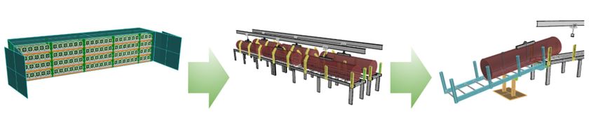
systems, and replaced the loadout of the forward VLS cells from Tomahawk Land Attack Missiles
(TLAMs) and ESSMs to only Vertically-Launched Anti-Submarine Rockets (VLAs). Figures 1
and 2 show forward and aft perspective views of the final DD(A) design.

                               Figure 1: DD(A) Forward Perspective View

                      Figure 2: DD(A) Aft Perspective View featuring MQ-8B Hangar

Based on the systems removed and added from the baseline Flight IIA DDG, the study determined
that the DD(A) design would save approximately $389 million per hull in acquisition costs and
$598 million per hull in total life cycle costs. The study concluded that this proposed solution,
while successful in reducing the cost per hull and having improved ASW capability over the
baseline Flight IIA DDG, was not the optimal way to create a dedicated ASW platform. The study
recommends either using a smaller platform as the basis of conversion, or to allow more substantial
modifications to the baseline Flight IIA DDG to accommodate more aviation assets or a different
type of ASW operational profile, such as acting as a command center for a fleet of unmanned
surface vehicles.
Commercial Working Boat to Minelayer Conversion
    LT Nathan E. Maxwell, USN; LT Matthew T. Valcourt, USN; LT Kelli M. Waterman, USN
A growing threat to U.S. Naval supremacy requires a new emphasis on the role of mine warfare.
In contrast with the advancement of military technology, mine warfare continues to be a highly
asymmetric threat with considerable strategic and tactical advantages. In addition to denial of
access or delaying enemy combatant movements, mines are an effective, low cost and low risk
means of sinking or damaging enemy vessels and restricting merchant shipping to an enemy state.
Currently, the U.S. Navy surface fleet has no capability to lay mines, with all minelaying
conducted by aviation or submarine assets. The objective for this project was to design a
conversion concept that could quickly and inexpensively convert a commercially available
working boat into a minelayer for use by the U.S. Navy surface fleet.

This study focuses on vessel type selection and mine storage, transfer and launching system
concept development with a focus on affordability, scalability and modularity. The final design
presents a highly modular “bolt-on” mine storage and launching system. The entire mine storage
and transfer system is designed to be fabricated inside International Standard Organization (ISO)
shipping containers, which can be quickly installed on a conversion vessel. In an effort to increase
modularity, commercially available equipment was used as much as possible, with very few
components requiring custom fabrication.

The Platform Supply Vessel (PSV) ship class was chosen as a baseline for this ship conversion
due to the working deck area and strength, load capacity, range, speed and crew accommodations
inherent to the class. Additionally, this vessel class is ubiquitous and available for acquisition. In
cooperation with Jensen Maritime Naval Architecture Firm based out of Seattle, Washington, the
Jensen 3000 PSV was chosen for the study. An optimized loadout was designed and analyzed
using this vessel. Although this study was conducted on a specific PSV, the design concept is
flexible enough to implement on any working boat with sufficient deck space, weight margin, and
deck strength. Due to this modularity, the design can be implemented with pre-fabricated “plug
and play” pieces based on the space and weight capacity available or desired payload capabilities.

The mine storage and launch systems consist of 20’ or 40’ shipping containers. Storage containers
use warehouse pallet racking systems to store palletized mines which can be used to reload the
transfer and launch rails within the launching containers. The launch containers are connected in
rows spanning the length of the deck and transport the mines on powered rollers to ramps at the
stern of the ship as shown in Fig. 1 and Fig. 2. Ramps, consisting of gravity fed free roller sections,
are supported by pinned connections to the conveyor roller sections and may be stowed when not
in use to permit clandestine transit to and from a minefield location. The subsystems of the
conversion are shown in Fig. 3. Final design parameters are shown in Table 1.

A key insight gained from this study was the density of payload capacity to cost compared to what
was expected at the outset of the project. Ultimately, the payload capability in the final design
exceeded the objective by over 500%, while coming in 69% under budget. Table 2 shows a
breakdown of modular cost and performance. These are significant margins that grant the sponsor
ample flexibility to meet strategic minelaying objectives with a surface asset such as the one
examined in this study. The project team concluded that a conversion of a commercially available
working vessel to an asset capable of laying mines is cost-effective, feasible and can provide
significant capability to fill a strategic gap in the current U.S. Navy surface fleet.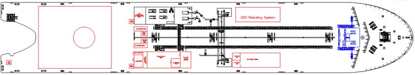
Fig 1. Final Conversion Design with Full Loadout         Fig 2. Deck Layout for Final Design

                             Fig. 3. Mine Storage, Transport and Launching Systems

                       Maximum Speed                                       17 kts
                       Endurance Speed                                     12 kts
                           Range                                         10,472 nm
                       Accommodations                                    20 people
                         Endurance                                       36.3 Days
                                                                 108 Quickstrike Mk 65 OR
                       Payload Capacity
                                                                   258 Quickstrike Mk 62
                             Cost                                       $622,125.41
                       Minefield Density                              100 yds at 15 kts
                                  Table 1: Final Conversion Design Parameters

                                      Launching System                            Storage System
Container     Payload                    Max Launch
                             Capacity                      Cost           Capacity              Cost
                                             Rate
               Mk 62           10          7.5 sec     $34,511.40           108               $9,159.26
   40’
               Mk 65            6           11 sec     $34,511.40            18               $8,133.18
               Mk 62            4          7.5 sec     $17,309.69            48               $4,970.76
   20’
               Mk 65            2           11 sec     $17,309.69           N/A                  N/A
                             Table 2: Per Container Material Cost and Performance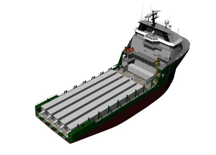
Commercial Cruise Ship to Hospital Ship Feasibility Study
LT Elliot Collins, USN; LT Megan Hagen, USN; LT Joshua Malone, USN
The Department of Defense has two T-AH class hospital ships in operation, the United States
Naval Ship (USNS) Mercy (T-AH-19) and USNS Comfort (T-AH-20), which were converted
from oil tankers in the 1980s and are now scheduled to be decommissioned in the mid-2030s.
Multiple replacement options have been presented. Cruise ships function similarly to hospital
ships by constantly receiving large guest populations and supplying the necessary support
capabilities throughout their stay onboard. Therefore, a cruise ship would require less
modification during the conversion process than a comparably sized industrial vessel. This
project was also motivated by the COVID-19 pandemic. New hospital ships could assist with
pandemic response, and cruise line companies currently have increased motivation to sell their
ships. This project aimed to determine if acquiring and converting a cruise ship would be a
lower cost, less complex alternative to constructing a new hospital ship.
The main design requirement based on fleet feedback was that future hospital ships needed to be
more expeditionary and designed with increased focus on Humanitarian Aid/Disaster Relief
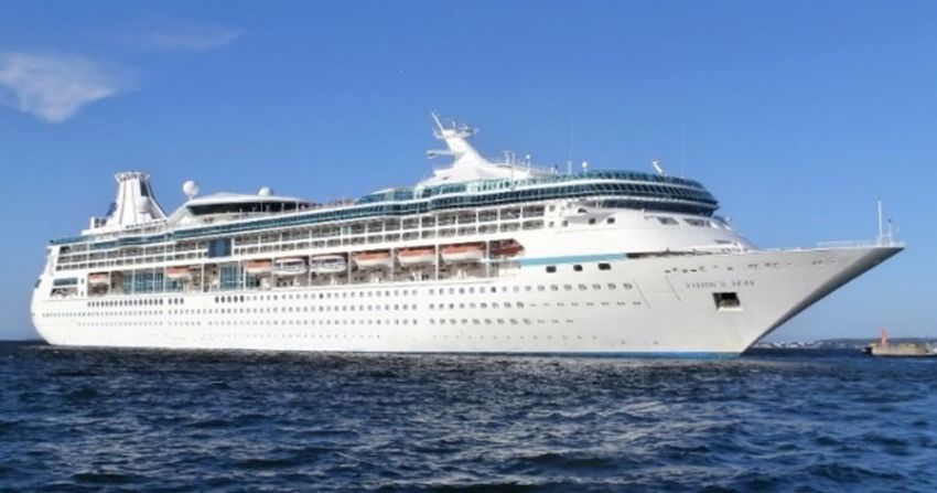
(HA/DR) operations. For the baseline cruise ship, the Vision class cruise ships from the Royal
Caribbean Group were selected due to their smaller size, optimal speed, range, electrical
capacity, and guest capacity. A 3D model was generated to better understand the space
available, and 2D deck plans were generated to establish the Hospital Ship Conversion (HSC)
arrangement. The HSC was equipped with a flight deck based on the LPD-17, and specialty
patient elevators were added throughout the center of the ship. A wheelchair-accessible brow
and converted lifeboat tenders were included to optimize patient access to the ship, and guest
spaces were converted to flexible patient spaces which allowed a single ward to be used in
multiple configurations based on mission needs. With these modifications, the team analyzed
the ship’s weight changes (which were within 0.5%), and a weight-based cost estimate was
developed using the MIT cost model. From this analysis, the HSC would maintain stability,
maneuvering and seakeeping capabilities comparable to the Vision class, and the total cost for
the conversion of two ships was estimated around $3.1-$5.2 billion. Lastly, the team validated
the proposed deck plans by analyzing patient flow paths for the most anticipated patient
scenarios to ensure each arrangement minimized both the required distance traveled throughout
the ship to receive care and was free of obstacles.
In conclusion, a cruise ship could serve as an effective baseline for a hospital ship conversion.
Many features of a cruise ship can be repurposed or directly used in a converted hospital ship,
and with the Vision class specifically, the HSC was able to utilize the existing machinery
equipment, propulsion system, water production plant, crew living spaces, dry and refrigerated
storage capacities, food-handling spaces and guest rooms. Repurposing so much space and
equipment is uncommon for conversion projects, and using most of the original ship could help
reduce the required conversion timeline by reducing the project’s complexity. Therefore,
converting a cruise ship to a hospital ship could have the added benefit of being less strenuous on
the constructing shipyard’s schedules compared to acquiring a new hospital ship. Additional
areas of study and further recommendations exist, but in short, a cruise ship provided an optimal
starting point for conversion to a hospital ship.
Figure 1: Vision class Cruise Ship

Figure 2: Hospital Ship Conversion (HSC)

                   2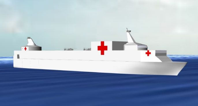
Conversion of an Articulated Tug Barge into an
                       Unmanned Naval Logistics Platform

                       LT Dayne Howard, USN; LT Scott Oberst, USN

The Marine Corps and Navy are interested in using barges as refueling and rearming stations in
order to support small, outlying land bases and to extend the reach of small surface and aerial
vehicles. This project was to study the potential conversion of a 125,000 BBL asphalt articulated
tug barge (ATB) to serve this purpose. A key objective was to make the converted articulated tug
barge (CATB) capable of refueling unmanned surface vehicles (USVs) and unmanned aerial
vehicles (UAVs) while being unmanned itself, which presented technological capability, safety,
and security challenges. Additionally, the CATB was to preserve the traditional ability to refuel
manned surface and aerial vehicles.

The conversion design philosophy stressed the importance of retaining the utmost amount of fuel
oil storage volume, keeping costs affordable, and designing the magazine to be small but
versatile. The following design variables were analyzed: size and location of the flight deck,
pitch and roll control necessary to land aircraft, size of the magazines, number of magazines,
location of magazines, USV and UAV refueling systems, and security measures.

The final design for the CATB featured a flight deck for either landing aircraft or hosting a High
Mobility Artillery Rocket System (HIMARS), two magazines for armament reloading of manned
helicopters, one of which was large enough to accommodate a HIMARS reload. The CATB
allocated the space, weight, and power for a UAV refueling system and a USV refueling
technology in development.

The study identified many unmanned challenges that require further study and solutions. Current
standard practice security measures operationally limit the deployment of the CATB. Ensuring
that equipment on the CATB can be completely, remotely monitored and controlled is a difficult
task by itself, but it also comes with the added challenge of doing so securely in the cyber
domain. Unmanned fueling comes with the danger of fuel spills and fires that will need to be
addressed without immediate personnel response. Existing flight deck firefighting equipment
could be utilized but automatic detection and activation systems will need to be developed.

From a naval architectural standpoint, an unmanned barge as a logistics node is shown to be
feasible. The particular ATB in the study was larger than necessary and smaller ATBs could hold
even more promise in cost saving efforts. The team concluded that ATBs are an affordable,
promising route for serving some of the Navy and Marine Corps’ logistical needs.
Barge Characteristics
Displacement 4730 LT (lightship); 20730 LT (fully loaded)
Length 455 ft
Beam 80 ft
Draft 12 ft (unloaded), 23 ft (fully loaded)
Endurance Speed 12 knots
UAV Refueling Stations 2
USV Refueling Stations 1
Aircraft capable V-22(unloaded, SH-60, CH-53, AH-1, MQ-8
Full Magazine Loadout 4 torpedoes, 6 Hellfire, and 75 sonobuoys;
or 1 HIMARS reload
JP-5 Storage Capacity 5.25 million gallonsYou can also read