ECOFLOW SMART GENERATOR USER MANUAL
←
→
Page content transcription
If your browser does not render page correctly, please read the page content below
EcoFlow Smart Generator User Manual
Disclaimer

Users are expected to read this User Manual carefully and ensure they have

fully understood the content before using this product. Please keep this User

Manual for future reference. Any incorrect usage may result in severe injury

to the user or others, damage to the product or loss of property. By using

this product, the user will be deemed as having understood, recognized

and accepted all the terms and contents of the User Manual, and will be

responsible for any incorrect usage, and all the consequences arising

therefrom. EcoFlow hereby disclaims any liability for any losses due to the

user's failure to use the product according to the User Manual.

Subject to compliance with laws and regulations, our company has the

final right to interpret this document and all documents of and related to

this product. Any update, revision or termination of the content thereof, if

necessary, will be made without prior notice, and users must visit the official

website of EcoFlow for the latest information regarding the product.

EcoFlow Smart Generator (hereinafter referred to as the Generator)
Contents   1. Safety Guidelines                                      1

               1.1 Safety Warning                                    1
               1.2 Safety Instructions                               1
               1.3 Important Labels                                  2

           2. Quick Start                                            3

               2.1 Appearance Description                            3
               2.2 Introduction to the Icons on the Display Screen   5
               2.3 Before You Use the Product                        6
               2.4 Using the Product                                 9
               --2.4.1 Startup                                       9
               --2.4.2 Turning Off                                   10
               --2.4.3 AC Connections                                10
               --2.4.4 DC Charging                                   11
               2.4.4.1 Charging the DELTA Max or the DELTA Pro       11
               2.4.4.2 C
                        harging the DELTA Max Extra Battery Pack    11
                       or the DELTA Pro Extra Battery Pack

               --2.4.5 Using the App                                 12
               --2.4.6 Application Range                             12
               --2.4.7 Special Requirements                          12

           3. Maintenance and Servicing                              13

               3.1 Checking the Spark Plug                           14
               3.2 Adjusting the Carburetor                          14
               3.3 Replacing the Engine Oil                          15
               3.4 Air Filter                                        15
               3.5 Fuel Filter Strainer                              16
               3.6 Muffler                                           16

           4. Storage and Transportation                             17

               4.1 Draining the Fuel                                 17
               4.2 Storing the Generator                             17
               4.3 Rechargeable Battery                              17
               4.4 Use after storage                                 18
               4.5 Transportation                                    18

           5. Faults and Troubleshooting                             19

           6. Parameters and Specifications                          20

           7. Package List                                           20

           8. Circuit Diagram                                        21
1. Safety Guidelines
1.1 Safety Warning
The safety of you and others, as well as of property are of the primary importance. Please carefully read the
extremely important safety warnings we have written in the User Manual and the sticker of the generator set.
This is to remind you of the potential dangers which may harm you and others. Before each safety warning is
a symbol and one of the three following words: danger, warning or caution.
These words indicate:
Danger If you fail to follow the instructions, your life will be at risk or you will be severely injured.
Warning If you fail to follow the instructions, your life may be at risk or you may be seriously injured.
Caution If you fail to follow the instructions, your generator set and other property may be damaged.
1.2 Safety Instructions
Please read the User Manual carefully before using the generator in order to avoid accidents.
Do not use indoors and keep away Do not use in damp Make sure that no fuel is
from doors, windows and vents environments spilled when refueling
Keep any combustibles at Do not smoke when refueling Switch off the engine
least 1m / 3ft away before refueling
Earthing the Generator
The generator is equipped with system grounding, which is used to connect the generator’s frame components
to the ground terminal in the AC outlet. The system grounding doesn’t connect to the AC neutral.
Connect the Generator to the Electrical System
Do not connect the generator to the electrical system of a building, unless an isolation switch has
been properly installed by a licensed electrician. Please comply with all applicable laws and electrical
regulatory requirements.
Caution
Keep the air inlets in the side of front panel, the muffler and the bottom of generator clean and
unblocked and prevent any debris, mud or water from entering. The generator, the controller or the
engine may be damaged if these air inlets become blocked. Do not transport, store or use the generator
together with other products. Any oil leaks may damage the generator or endanger your personal
safety as well as your property.
11.3 Important Labels Please refer the following stickers carefully before starting to use the product. 2
2. Quick Start

2.1 Appearance Description

Fuel Cap Breather Valve
                             Fuel Cap

                                           Maintenance Cover

                                        Muffler

                                                           3
Electric Start Switch LCD Screen
Carbon Monoxide Alert Light IOT Reset Switch
Engine Oil Alert Light AC Power Button
Extra Battery Port (XT150) AC Output Sockets
Ground Terminal
Starter Grip Engine Switch
Spark Plug
Rechargeable Battery
Oil Drain Bolt
Air Filter
Engine Oil Dipstick
Carbon Monoxide Alert Light: When the carbon monoxide sensor detects that the concentration of
carbon monoxide is about to exceed the standard, the generator will automatically stop and the carbon
monoxide alert light will flash for 5 minutes. During this course, the generator cannot be started.
42.2 Introduction to the Icons on the Display Screen
Wi-Fi Status
Remaining Power Percentage Total Run Time
Remaining Running Time
Output Power
Rechargeable
Battery Fault Alert
Low Temperature Alert
Error Code
High-Temperature Alert Carbon Monoxide
ECO
Alert
Eco Mode Communication Connection
Output Overload Alert
AC Output DC Output
Remaining Power Percentage: If the remaining fuel level is lower than 600 mL/20.3 oz., the indicator
will be at 0% charge and flash to warn you.
Wi-Fi Status: After pressing the IOT button for 3 seconds, the Wi-Fi status will flash on the LCD screen
which indicates that the product is ready for pairing. There’re two ways to connect the product with
the App, either directly connect to the product’s hotspot or using the Internet. If the App is successfully
connected to the product’s hotspot, the icon will keep flashing; if it is successfully connected to the
Internet, the icon will stay on.
Error Code: Please refer to the EcoFlow app for specific information on error codes.
ECO Mode: In ECO mode, the Smart Generator will adjust its rotational speed to match the output
power demand, in order to conserve fuel and reduce noise. This is the default mode. You can modify the
mode settings in the EcoFlow app. For details please refer to 2.4.5.
* See Section 5 for more troubleshooting steps.
52.3 Before You Use the Product
Refueling
Danger
Please read the Safety Guidelines carefully before refueling as
fuel is inflammable and toxic. Do not overfill the fuel tank, as
fuel may expand and spill out when the fuel tank warms up.
Be sure to tightly close the fuel cap after refueling.
Open fuel cap
Caution
Clean away the residual fuel with a clean and soft cloth after
refueling to avoid damage to the rubber shell. Please use Red Indicator
unleaded fuel rather than leaded fuel which may severely
damage the internal parts of generator. Take off the fuel cap
and fill up until the red indicator.
Fuel Filter
Strainer
Recommended fuel: unleaded fuel Refueling
Fuel tank capacity: 1.05 gal. / 4 L
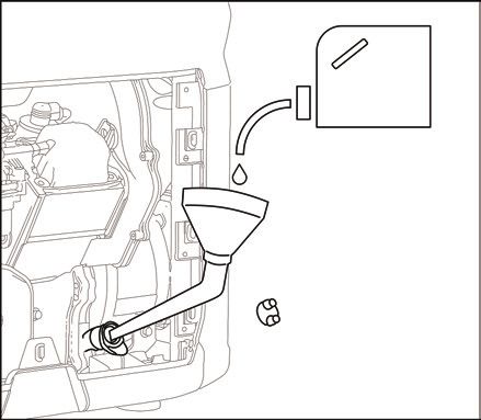
6Add Generator Engine Oil
Caution
There is no engine oil in the generator when delivered from the
factory. Do not start up the generator until after adding sufficient
engine oil. Do not tilt the generator when adding engine oil, to
prevent damage to the generator due to adding excessive oil.
1. Place the generator on a level plane.
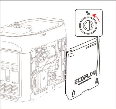
2. Turn the maintenance cover knob to and take off the maintenance cover. Removing the
maintenance cover
3. Unscrew the lid and oil dipstick.
4. Inject the specified amount of recommended engine oil, and screw
the lid and oil dipstick closed tightly. Reinstall the maintenance cover
and turn the knob to Closed.
Recommended engine oil: SAE SJ 10W-40
Grade of recommended engine oil: API Grade SJ or higher
Oil capacity: 0.1 gal. / 0.38 L
Refilling the engine oil
Rechargeable Battery Connection
The generator cannot be started by the Electric Start switch unless
connected to the internal battery.
Turn the maintenance cover knob to , take off the maintenance
cover and connect the positive and the negative wires of the battery
respectively.
Connecting the positive
and negative wires
7Checking Before Use
Warning Please check the following components carefully each time before using the generator.
a) Check the fuel level
Take off the fuel cap and check the fuel level. Inject more fuel into the tank if the fuel level is too low.
b) Check the engine oil level
Make sure there are no engine oil leaks.
Check the engine oil level. If the oil level is low, the engine oil
alarm system may shut off the engine.
1. Unscrew the lid, take out the oil dipstick and wipe it clean.
2. Dip the oil dipstick into the oil filler without screwing it in, and
check the oil level. Engine oil level check
3. Add the recommended amount of engine oil if the oil level is low.
4. Screw the oil dipstick and lid firmly shut.
c) Check whether the rechargeable battery is connected correctly
Turn the maintenance cover knob to Open, take off the maintenance cover and check whether the
positive and the negative wires of battery are connected correctly.
Malfunctions While Running
Check for any issues while the generator is running and consult EcoFlow for further technical support if
necessary.
82.4 Using the Product
Danger
Read the Safety Guidelines before use.
Do not use the generator in a closed space as the exhaust fumes may result in a loss of
consciousness or even death. Use it in a well-ventilated place.
Do not connect the AC Output Socket with any electrical equipment before starting the generator.
Tips: The generator is used at 5 ℉-104 ℉(-15 ℃—40 ℃). The generator can operate at rated power under
standard atmospheric conditions (“standard atmospheric conditions” - ambient temperature 77℉ (25 ℃)
- atmospheric pressure 100KPA - relative humidity 30%). Once the temperature, humidity and altitude
exceed standard atmospheric conditions, the output of the generator will drop. Using for a long time in
a high temperature (above 95℉ /35 ℃) environment will affect the service life of the generator and the
built-in battery. Moreover, if the generator is used in any narrow space, its load must be reduced as the
generator cooling is affected.
2.4.1 Startup
1. Turn the fuel cap breather valve knob to "ON". 2. Turn the Engine Switch to "ON".
The generator can be started using any of the four methods below:
a) Electric Start Switch
Press and hold the Electric Start Switch for 2 seconds to execute the
start-up program and start up the generator.
Tips: To save battery power consumption, when the Engine Switch is
at the "ON" position, if the generator fails to start up, the power will be
disconnected after 3 mins and the display screen will switch off. In this
situation, press the start button to activate the screen display to then re-
enable the Electric Start Switch.
Manual start
b) Manual start
Pull the Manual Starter Grip until the line tightens and push it by force.
Tips: When starting by hand, it is necessary to hold the generator still to prevent it from tilting or
tumbling during the pull-push process.
c) Self-start, see paragraph 2.4.4
d) Starting through the app, see paragraph 2.4.5
Tips: When the ambient temperature is below 32 ℉(0 °C), the engine will need to warm up for three
minutes after being started, during which time no load should be loaded.
92.4.2 Turning off
To turn the engine off in an emergency, turn the engine switch to the “OFF” position. In any other
circumstances, please follow the below steps.
1. Switch off all electrical equipment and disconnect them from the generator.
2. There are three methods to turn off the generator:
a) Using the Engine Switch: Turn the Engine Switch to "OFF" to turn off the generator.
b) Using the Electric Start button: Press and hold the Electric Start button for 2 seconds to stop the engine.
c) To turn off the generator through the app, please refer to paragraph 2.4.5.
Tips: When the AC output switch and DC output switch are turned off, in order to save power, the
generator will automatically turn off after 10 mins.
3. Wait until the generator is completely cooled down, then turn the Engine Switch and the fuel cap
breather valve knob to "OFF".
2.4.3 AC Connections
1. Start the generator.
2. Insert the plug into the AC Output Socket and check that the on-screen AC output port icon is illuminated.
3. Switch on the electrical equipment.
Tips: While the engine is running, the AC output can be connected and disconnected by the AC switch
button. If the generator supplies power to multiple loads or electrical equipment, please start electrical
equipment in descending order, according to the size of the load.
Warning Switch off all electrical equipment before inserting plugs.
Caution
Make sure that all electrical equipment including wires and plugs are in good condition before being
connected to the generator, and confirm that all loads carried by the generator are within the rated load
range and that the load current is within the rated current range.
Tips: Make sure that the generator is grounded. If any electrical equipment needs to be grounded, the
generator must also be grounded.
102.4.4 DC Charging
2.4.4.1 Charging the DELTA Max or the DELTA Pro
1. Turn the fuel cap breather valve knob to "ON" (see Step 1 in paragraph 2.4.1).
2. Turn the Engine Switch to "ON" (see Step 2 in paragraph 2.4.1).
3. Connect with the DELTA Max or the DELTA Pro through the 5m/ 16.4ft Extra Battery Connection
Cable.
4. If the remaining power of the DELTA Max or the DELTA Pro falls to the lower limit, it will send a
request to the generator to recharge. The generator will respond and start recharging.
Tips: If the remaining power of the DELTA Max or the DELTA Pro does not fall to the lower limit, the
generator can be started by hand to start recharging.
5. Once the power capacity of the DELTA Max or the DELTA Pro reaches the upper limit, it will send a
request to the generator to stop charging. The generator will respond and stop DC recharging.
Tips: The upper and lower limits may be set on the app. The upper limit is 100% by default and the lower
limit is 20% by default. When used together with the DELTA Max or the DELTA Pro for recharging,
to improve the utilization efficiency of fuel, it is recommended to set the upper limit as 80%. When
charging with DC, the AC switch can be turned on for AC output. The total power of DC+AC is
1800 W, with AC output as the priority.
Tips: The DELTA Pro needs to use the dedicated adaptor plug,which is included in the DELTA Pro standard
configuration.
2.4.4.2 Charging the DELTA Max Extra Battery Pack or the DELTA Pro Extra Battery Pack
1. Turn the fuel cap breather valve knob to "ON" (see Step 1 in paragraph 2.4.1).
2. Turn the Engine Switch to "ON" (see Step 2 in paragraph 2.4.1).
3. Connect to the DELTA Max Extra Battery or DELTA Pro Extra Battery with the 5m/ 16.4ft Extra Battery
Connection Cable.
4. Switch on the DELTA Max Extra Battery or DELTA Pro Extra Battery and it will send a request to the
generator to recharge. The generator will respond and start recharging.
5. When the DELTA Max Extra Battery or DELTA Pro Extra Battery is fully recharged, it will send a
request to the generator to stop charging. The generator will respond and stop DC recharging.
Tips: The DELTA Pro Extra Battery Pack needs to use the dedicated adaptor, which is included in the
DELTA Pro standard configuration.
112.4.5 Using the App
You can control and view the information and data of the product through the
EcoFlow app.
Read the EcoFlow App user guide and access the download link here:
https://ecoflow.com/pages/ecoflow-app.
2.4.6 Application Range
Please make sure that the total load of the generator is within the rated range before using the
generator, or otherwise the generator may be damaged.
Application
0.4–0.75
Power Factor 1 0.8–0.95
(Efficiency 0.85)
Output ≤1800 W ≤1440 W ≤612 W
Caution
When this generator is supplying power to precision instruments, electronic controllers, personal
computers and microcomputers, please keep the generator a sufficient distance away from any of the
foregoing equipment to avoid electromagnetic interference, and at the same time, to ensure that the
generator will not be interfered with by these electronic devices.
If this generator is used to supply power to medical devices, it is recommended to consult with
the corresponding equipment manufacturers and technicians first. This is because some electronic
equipment or general purpose machines in hospitals require a strong current upon startup and may not
be able to use the generator. Please contact the equipment manufacturer for confirmation even if the
respective start parameters of the equipment satisfy the conditions listed in the table above.
2.4.7 Special Requirements
Warning
There may be local laws or regulations applicable to the intended use of the generator set. Please
consult with qualified electricians, electrical inspectors or the local authorities with jurisdiction for
further information.
In some areas, generator sets must be registered with local utility companies.
Generator sets, if used on construction sites, may be subject to regulations.
123. Maintenance and Servicing
Proper maintenance and servicing is essential to ensure safe, economical and reliable usage. This also
helps minimize your environmental impact.
You must regularly check and service your generator to keep it in optimal condition based on the
schedule below.
Servicing Once every
Within the first Then once every
Intervals three months or
month or after year or every
Each Time every 50 hours
20 hours of 100 hours of
Item of operation
operation operation
thereafter
Check – Add
Generator Engine
Oil Replace
Check – Add
Air Filter Element
Clean
Replace
Sediment Bowl Clean
Spark Plug* Clean – Adjust
Spark Plug Arrester Clean
Idle Speed ** Check - Adjust
Valve Clearance ** Check - Adjust
Fuel Tank and
Clean
Fuel Filter **
Fuel Pipe* Check Every 2 years (or replace it if necessary)
Cylinder Head, Remove any Every 300 hours
Piston carbon deposits **
* These items should be replaced if necessary
** These items should be serviced by their respective dealers unless the user has the appropriate tools and
maintenance capacity
Caution
If the generator set works at high temperature under high loads, the engine oil should be replaced every
25 hours.
If working in dusty or harsh environments, the air filter element should be cleaned every 10 hours and, if
necessary, replaced every 25 hours.
Spot check items based on either the cycle or length of time, whichever comes first.
If you have reached a servicing interval, servicing must be performed as required based on the table
above as soon as possible.
Danger
Turn off the generator before starting any maintenance. Place the generator on a level spot and
separate the spark plug cap from the spark plug to prevent the generator from starting up.
Do not use the generator such in poorly ventilated places such as rooms, rail tunnels or caves. Be
sure to keep the working area well ventilated. Exhaust gas from the generator contains toxic carbon
monoxide fumes. Inhaling these fumes may lead to shock, loss of consciousness or even death.
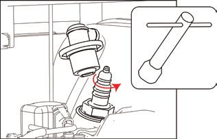
133.1 Checking the Spark Plug
The spark plug is an important part of the generator and must be checked regularly.
1. Turn the maintenance cover knob to and take off the maintenance
cover.
2. Take off the spark plug cap.
3. Use the spark plug socket and revolve it counterclockwise to remove
the spark plug.
4. Check for any fading in color and remove any carbon deposits. The
porcelain center around the spark plug center electrode should
be moderately light brown if it is in good condition. The electrode Removing the
spark plug
should be replaced if worn, or if the insulation is peeling, cracked or
dirty.
5. Check the model of the spark plug and that it has sufficient
clearance. If required, correct the gap.
Standard spark plug: A5RTC
Spark plug clearance: 0.6–0.8 mm
Tips: The engine may be damaged if the spark
0.6-0.8mm
plug is not at the correct clearance height.
Spark plug clearance
6. Reinstall the spark plug with a torque of 13.5±1.5 Nm.
Tip: If installing without a torque wrench, a good method is to tighten
until tight, then continue to turn by a further 1/4-1/2 rotation.
7. Reinstall the spark plug cap on the spark plug.
8. Reinstall the maintenance cover.
3.2 Adjusting the Carburetor
The carburetor is an important part of engine, and should be adjusted by the dealer who has the
professional knowledge, data and equipment to ensure it is adjusted correctly.
Usage in high altitude areas
In high altitude areas, the atmospheric pressure may reduce the amount of air intake, decline the performance
and increase the fuel consumption of standard carburetors. Moreover, the dense mixture may contaminate
the spark plug and lead to starting difficulties. When the generator is running at high altitudes (above 3000
feet/914 m), the emissions may increase.
Modifying the carburetor can improve its high altitude performance. If you plan to operate your generator at
high altitude (above 3000 feet/914 m) areas for a long time, please contact your after-sales service team to
help to modify it. When using the modified carburetor in high altitude areas (if within the service life of the
generator), the generator will satisfy every emission standard.
143.3 Replacing the Engine Oil
Warning Do not drain the engine oil immediately after the generator is switched off. The oil
temperature will be very high. Please take care not to get scalded when draining the oil.
1. Place the generator on a level plane, start it up and keep it running for several minutes to increase
its temperature. Then turn it off. Turn the Engine Switch and the fuel cap breather knob to "OFF".
2. Turn the maintenance cover knob to and take off the maintenance cover.
3. Unscrew the lid and oil dipstick.
4. Place the oil basin under the generator and tilt the generator. The oil will drain quickly.
Tips: Improper disposal of engine oil may harm the environment. If you replace the engine oil yourself,
please dispose of the used oil properly. Store the used oil in a sealed container and take it to your
nearest oil recycling center. Do not pour it into any trash can, onto the ground or into the sewer.
5. Place the generator in its original horizontal state.
Caution Do not tilt the generator when adding engine oil to prevent damage to the generator due to
adding excessive oil.
6. Refill the oil to the proper level.
7. Wipe the oil dipstick clean and remove any spilled oil.
Warning Prevent any foreign objects from entering the inside of the engine.
8. Tighten the oil dipstick and lid.
9. Reinstall the maintenance cover and turn the knob to Closed.
3.4 Air Filter
1. Turn the maintenance cover knob to and take off the maintenance cover.
2. Take off the screws and the air filter cover.
3. Take off the foam filter element.
4. Clean the foam filter element with soapy water or a nonflammable solvent
and dry it.
5. Add oil to the foam filter element and squeeze out the excess oil. The
foam filter element should be wet but should not drip any oil.
6. Place the foam filter element into the air filter.
Tips: 1. Make sure that the surface of the foam filter element is in close
Removing the air filter cover
contact with the air filter, leaving no gap between them.
2. Do not start the generator before reinstalling the air filter as excessive
toxic gas may be produced and foreign objects may enter the engine,
causing wear to the engine block.
7. Install the air filter cover back to its original position and tighten the screws.
8. Reinstall the maintenance cover and turn the knob to Closed.
Caution Do not twist the foam filter element, to prevent any damage to it.
Wash clean Press and air dry Add correct Press (do not twist)
(do not twist) amount of oil
153.5 Fuel Filter Strainer
1. Take off the fuel cap 2. Clean the fuel filter 3. Wipe the filter screen and 4. Reinstall the fuel
and fuel filter screen. screen with fuel. place it back into the fuel. cap.
Warning Never use fuel in any place near smoke or flames.
Caution Be sure to tighten the fuel cap.
3.6 Muffler
1. Unscrew the bolts.
2. Take off the muffler cap, muffler block and spark plug
arrestor.
3. Clean the carbon deposits on the muffler block and the
spark plug arrestor gently with a steel wire brush to avoid
any damage or scratches to the muffler block and spark
plug collector.
4. Check whether the muffler block or the spark plug arrestor
Clean any carbon deposits
is damaged, and replace it if damaged.
5. Reinstall the parts in turn.
Warning
Once the generator starts running, the engine and the muffler will become scalding hot. Do not let
your skin or clothes directly touch the engine or muffler during your checks and maintenance.
164. Storage and Transportation
If you plan to place this generator into long-term storage, you need to take some storage measures to
prevent premature aging of the generator.
4.1 Draining the Fuel
1. Turn the Engine Switch to "OFF".
2. Open the fuel cap, take out the fuel filter screen, drain all the fuel from the fuel tank into a temporary
fuel tank and reinstall the fuel cap.
3. Start the generator. The remaining fuel will be used up in about 20 minutes. The generator will turn
off when there is no fuel left.
Do not connect any electrical equipment to the generator.
The time it takes for the generator to run depends on the remaining amount of fuel inside the fuel tank.
4. Turn the maintenance cover knob to and take off the maintenance cover.
5. Loosen and remove the oil drain bolt on the carburetor and drain the fuel from the carburetor into
the temporary fuel tank.
6. Turn the Engine Switch to “OFF”.
7. Screw in and tighten the oil drain bolt.
8. Reinstall the maintenance cover and turn the knob to Closed.
9. Turn off the fuel cap breather valve knob after the engine cools down completely.
Warning As fuel is highly volatile and toxic, please carefully read the "Safety Guidelines" for handling
instructions.
Caution Wipe any spilled fuel away with a clean soft cloth to prevent it from damaging the plastic shell.
4.2 Storing the Generator
Take the following steps to protect parts such as the engine body and piston rings which are the most
susceptible to corrosion.
1. Take out the spark plug, inject 10 mL/0.34 oz. of engine oil, reinstall the spark plug, and pull the
Starter Grip for several minutes so that the engine oil can fully lubricate the cylinder block.
2. Pull the Starter Grip until it becomes tight (to prevent the cylinder block and valves rusting).
3. Wipe the generator's surface clean, place the generator in a well-ventilated and dry place and cover it.
4.3 Rechargeable Battery
Disconnect the battery each time you store it for a longer period of time and reconnect it before using
it again.
Attention: The battery should be charged and discharged once every 3 months. It will charge while the
engine is running.
174.4 Use after storage
If the generator is stored with fuel in the fuel tank and carburetor, conduct servicing as required in the
table below before using again.
Storage Duration Recommended Servicing Procedure to Prevent Difficult Startups
Within one month No preparation needed
One to two months Evacuate the fuel and inject fresh fuel
Evacuate the fuel and inject fresh fuel
Two months to one
year Drain the fuel from Carburetor Drain Cup ①
Drain the fuel from Sediment Bowl ②
Evacuate the fuel and inject fresh fuel
Drain the fuel from Carburetor Drain Cup ①
Over one year
Drain the fuel from Sediment Bowl ②
Drain the original fuel into a suitable storage container after moving it out of storage
and inject fresh fuel before starting it.
① Loosen and remove the oil drain bolt and drain all the fuel out of the carburetor. Drain the fuel into a
suitable container, and screw in and tighten the oil drain bolt.
② After turning off the Engine Switch, remove the Sediment Bowl, empty the gasoline from the bowl,
reinstall the Sediment Bowl and tighten it.
4.5 Transportation
Caution
When moving, storing or operating the generator, do not place it on its side. The engine oil may leak
and damage the engine or your property.
If the generator is constantly running, allow it to cool before being loaded onto the transport vehicle.
Hot engines and waste systems may cause burns and can cause certain materials to ignite. To prevent
fuel spills during transport, position the generator vertically in the standard operating position, and
turn the engine switch and the fuel cap breather valve knob to the “OFF” position.
During transportation, take care not to let the generator fall or be impacted.
185. Faults and Troubleshooting
Errors Content of Tips Error Type Possible Causes Recovery Methods
The fuel cap breather valve knob is in the Turn the fuel cap breather valve knob
OFF position to "ON"
The Engine Switch is in the OFF position Turn the Engine Switch to "ON"
Icon flashes There is no fuel left Refueling
Fuel system
The generator set was not properly
prepared for storage, or the gasoline was Empty the fuel tank and carburetor and
not evacuated, or the quality of injected refill with fresh fuel
fuel was poor.
The fuel filter is blocked. Carburetor faults, Send the generator set to your service
ignition failure, or stuck valves, etc. dealer, or refer to the Service Manual
Unable
to Oil Alert Indicator Low engine oil level. The engine oil alarm
Engine oil system Add engine oil
start stays on system may turn off the engine.
The spark plug is faulty, dirty or have Adjust the clearance or replace the spark
improper clearance plug
The spark plug has been moistened by the
Dry the spark plug with air and reinstall it
fuel (spilled outside the engine)
Electrical system
Oil Alert Indicator Send the generator set to your service
Communication failure
stays on dealer, or refer to the Service Manual
Lack of battery power or the battery is
Icon stays on Pull by hand to start or replace the battery
damaged
CO exceeding
Turn off the generator and improve
Icon stays on specified standard Poor ventilation
ventilation
values
Remove the problem load, shut down and
Icon flashes AC overload protection Load-related problems
restart
Remove the problem load, shut down and
Icon flashes DC overload protection Load-related problems
No restart
output Over-temperature The air inlet is blocked or the ambient Check the air inlet or remove it from the high
The icon stays on
protection temperature is too high or the load is too large temperature environment or reduce the load
Battery over- The air inlet is blocked or the ambient Check the air inlet or remove it from the high
The icon stays on
temperature temperature is too high or the load is too large temperature environment or reduce the load
Communication failure: Communication failures may occur in two specific situations, as detailed below.
1) Normal failure: When the generator is connected to DELTA Max or DELTA Pro, if the generator goes
into sleep mode, a communication failure will occur. In this situation, press a button to activate the
generator and the communication failure will disappear.
2) Abnormal failure: If the communication failure does not disappear once the generator has been
activated or while the generator is running, this could indicate that the failure has been caused by a
problem with the generator.
If any alert occurs during the use of this product and if the alert icon does not disappear after the
foregoing methods are attempted or the product is restarted, please stop using it immediately.
If the above information still fails to solve your problem, please contact our professional service
personnel for further support.
196. Parameters and Specifications
Length × width × height 23.5×11.7×18.7 in/597×296×475 mm
Complete machine
Net weight Approximately62.8 lbs/28.5 kg
Type Inverter generator
Frequency 60 Hz
Rated voltage 120 V
Generator Rated power 1800 W (peak value 1900 W)
Power factor 1
DC output voltage 42–58.8 V
Maximum DC output current 32 A
Engine model R80-i
Engine type Single cylinder, four-stroke, forced-air cooling, overhead valve
Engine displacement 80 CC
Type of fuel Unleaded fuel
Volume of fuel tank 4 L/1.06 gal.
Engine
Generator engine oil volume 0.38 L/0.1 gal.
Continuous Working Time 3.5 Hr (full load)
Noise Level (at a distance of
56–67 dB (full load)
7 meters)
Model of spark plug A5RTC (TORCH)
Start mode Electric start
7. Package List
Smart Generator User Manual and Extra Battery Oil Funnel
Warranty Card Connection Cable
Screwdriver Spark Plug Socket Breaker Bar Double-Ended Spanner
208. Circuit Diagram
21California and Federal Exhaust and Evaporative Emissions Control
Warranty Statement
YOUR WARRANTY RIGHTS AND OBLIGATIONS
The California Air Resources Board, the United States Environmental Protection Agency and Chongqing
Rato Technology Co., Ltd. (Rato), are pleased to explain the exhaust and evaporative emissions (“emis-
sions”) control system warranty on your 2021/2022 small off-road engine/equipment. In California, new
equipment that use small off-road engines must be designed, built, and equipped to meet the State’s
stringent anti-smog standards. Rato must warrant the emissions control system on your small off-road
engine/equipment for the period listed below provided there has been no abuse, neglect or improper
maintenance of your small off-road engine/equipment leading to the failure of the emissions control
system.
Your emissions control system may include parts such as the carburetor or fuel-injection system, the ig-
nition system, catalytic converter, fuel tanks, fuel lines (for liquid fuel and fuel vapors), fuel caps, valves,
canisters, filters, clamps and other associated components. Also included may be hoses, belts, connec-
tors, and other emission-related assemblies.
Where a warrantable condition exists, Rato will repair your small off-road engine/equipment at no cost
to you including diagnosis, parts and labor.
MANUFACTURER’S WARRANTY COVERAGE:
The exhaust and evaporative emissions control system on your small off-road engine/equipment is war-
ranted for two years. If any emissions-related part on your small off-road engine/equipment is defective,
the part will be repaired or replaced by Rato.
OWNER’S WARRANTY RESPONSIBILITIES:
As the small off-road engine/equipment owner, you are responsible for performance of the required
maintenance listed in your owner’s manual. Rato recommends that you retain all receipts covering main-
tenance on your small off-road engine/equipment, but Rato cannot deny warranty coverage solely for
the lack of receipts or for your failure to ensure the performance of all scheduled maintenance.
As the small off-road engine/equipment owner, you should however be aware that Rato may deny you
warranty coverage if your small off-road engine/equipment or a part has failed due to abuse, neglect, or
improper maintenance or unapproved modifications.
You are responsible for presenting your small off-road engine/equipment to a Rato distribution center
or service center as soon as the problem exists. The warranty repairs shall be completed in a reasonable
amount of time, not to exceed 30 days.
If you have any questions regarding your warranty rights and responsibilities, you should contact Great
Lakes Technologies, LLC. at 800-232-1195 or techsupport@wenproducts.com.
22DEFECTS WARRANTY REQUIREMENTS:
(a) The warranty period begins on the date the small off-road engine/equipment is delivered to an ulti-
mate purchaser.
(b) General Emissions Warranty Coverage. Rato warrants to the ultimate purchaser and each subse-
quent owner that the engine or equipment is:
(1) Designed, built, and equipped so as to conform with all applicable regulations adopted by the Air
Resources Board; and
(2) Free from defects in materials and workmanship that causes the failure of a warranted part for a
period of two years.
(c) The warranty on emission-related parts will be interpreted as follows:
(1) Any warranted part that is not scheduled for replacement as required maintenance in the written
instructions must be warranted for the warranty period defined in Subsection (b)(2). If any such part
fails during the period of warranty coverage, it must be repaired or replaced by Rato according to
Subsection (4) below. Any such part repaired or replaced under the warranty must be warranted for the
remaining warranty period.
(2) Any warranted part that is scheduled only for regular inspection in the written instructions must be
warranted for the warranty period defined in Subsection (b)(2). A statement in such written instruc-
tions to the effect of “repair or replace as necessary” shall advise owners of the warranty coverage for
emissions related parts. Replacement within the warranty period is covered by the warranty and will not
reduce the period of warranty coverage. Any such part repaired or replaced under warranty must be
warranted for the remaining warranty period.
(3) Any warranted part that is scheduled for replacement as required maintenance in the written in-
structions must be warranted for the period of time prior to the first scheduled replacement point for
that part. If the part fails prior to the first scheduled replacement, the part must be repaired or replaced
by Rato according to Subsection (4) below. Any such part repaired or replaced under warranty must be
warranted for the remainder of the period prior to the first scheduled replacement point for the part.
(4) Repair or replacement of any warranted part under the warranty provisions must be performed at
no charge to the owner at a warranty station.
(5) Notwithstanding the provisions of Subsection (4) above, warranty services or repairs must be pro-
vided at distribution centers that are franchised to service the subject engine/equipment.
(6) The owner must not be charged for diagnostic labor that leads to the determination that a warrant-
ed part is in fact defective, provided that such diagnostic work is performed at a warranty station.
(7) Rato is liable for damages to other engine/equipment components proximately caused by a failure
under warranty of any warranted part.
(8) Throughout the emissions control system’s warranty period set out in subsection (b)(2), Rato must
maintain a supply of warranted parts sufficient to meet the expected demand for such parts and must
obtain additional parts if that supply is exhausted.
(9) Manufacturer-approved replacement parts that do not increase the exhaust or evaporative emissions
of the engine or emissions control system must be used in the performance of any warranty mainte-
nance or repairs and must be provided without charge to the owner. Such use will not reduce the war-
ranty obligations of Rato.
(10) Add-on or modified parts that are not exempted by the Air Resources Board may not be used. The
use of any non-exempted add-on or modified parts will be grounds for disallowing a warranty claim.
Rato will not be liable to warrant failures of warranted parts caused by the use of a non-exempted add-
on or modified part.
(11) Rato issuing the warranty shall provide any documents that describe that warranty procedures or
policies within five working days of request by the Executive Officer.
23(d) Emission Warranty Parts List for Exhaust (1) Fuel Metering System (i) Carburetor and internal parts (and/or pressure regulator or fuel injection system). (ii) Air/fuel ratio feedback and control system. (iii) Cold start enrichment system. (2) Air Induction System (i) Controlled hot air intake system. (ii) Intake manifold. (iii) Air filter. (3) Ignition System (i) Spark Plugs. (ii) Magneto or electronic ignition system. (iii) Spark advance/retard system. (4) Exhaust Gas Recirculation (EGR) System (i) EGR valve body, and carburetor spacer if applicable. (ii) EGR rate feedback and control system. (5) Air Injection System (i) Air pump or pulse valve. (ii) Valves affecting distribution of flow. (iii) Distribution manifold. (6) Catalyst or Thermal Reactor System (i) Catalytic converter. (ii) Thermal reactor. (iii) Exhaust manifold. (7) Particulate Controls (i) Traps, filters, precipitators, and any other device used to capture particulate emissions. (8) Miscellaneous Items Used in Above Systems (i) Electronic controls. (ii) Vacuum, temperature, and time sensitive valves and switches. (iii) Hoses, belts, connectors, and assemblies. (e) Emission Warranty Parts List for Evap (1) Fuel Tank (2) Fuel Cap (3) Fuel Lines (for liquid fuel and fuel vapors) (4) Fuel Line Fittings (5) Clamps* (6) Pressure Relief Valves* (7) Control Valves* (8) Control Solenoids* (9) Electronic Controls* (10) Vacuum Control Diaphragms* (11) Control Cables* (12) Control Linkages* (13) Purge Valves* (14) Gaskets* (15) Liquid/Vapor Separator (16) Carbon Canister (17) Canister Mounting Brackets (18) Carburetor Purge Port Connector *Note: As they relate to the evaporative emission control system. Rato will furnish with each new small off-road engine/equipment written instructions for the mainte- nance and use of the engine/equipment by the owner. 24
Générateur intelligent EcoFlow
     Manuel d'utilisation
Clause de non-responsabilité Les utilisateurs sont tenus de lire attentivement ce manuel d'utilisation et de s'assurer qu'ils ont bien compris son contenu avant d'utiliser ce produit. Conservez ce manuel d'utilisation pour vous y référer en cas de besoin. Toute utilisation incorrecte peut causer des blessures graves pour l'utilisateur ou d'autres personnes, endommager le produit ou entraîner des pertes matérielles. Il est considéré que si l'utilisateur utilise ce produit, il comprend, reconnaît et accepte l'ensemble des termes et contenus du manuel d'utilisation et est responsable de toute utilisation incorrecte et de toutes les conséquences qui en découlent. Par la présente, EcoFlow décline toute responsabilité en cas de pertes dues à une utilisation du produit non-conforme au manuel d'utilisation par l'utilisateur. Sous réserve du respect des lois et réglementations, notre entreprise a le droit final d'interpréter ce document et tous les documents relatifs à ce produit. Toute mise à jour, révision ou résiliation du contenu de celui-ci, le cas échéant, sera effectuée sans préavis et les utilisateurs devront consulter le site officiel d'EcoFlow pour obtenir les dernières informations concernant le produit. Générateur intelligent EcoFlow (ci-après dénommé le générateur)
Table des   1. Consignes de sécurité                                  1

matières         1.1 Avertissement de sécurité                        1
                 1.2 Instructions de sécurité                         1
                 1.3 Étiquettes importantes                           2

            2. Démarrage rapide                                       3

                 2.1 Description extérieure                           3
                 2.2 Présentation des icônes de l'écran d'affichage   5
                 2.3 Avant d'utiliser le produit                      6
                 2.4 Utilisation du produit                           8
                 --2.4.1 Démarrage                                    8
                 --2.4.2 Mise hors tension                            8
                 --2.4.3 Connexions CA                                9
                 --2.4.4 Charge CC                                    9
                 2.4.4.1 C
                          harge de la batterie DELTA Max ou de la    9
                         batterie DELTA Pro

                 2.4.4.2 Charge de la batterie DELTA Max Extra ou    9
                          de la batterie DELTA Pro Extra

                 --2.4.5 Utilisation de l'application                 10
                 --2.4.6 Plage d'application                          10
                 --2.4.7 Exigences spéciales                          10

            3. Maintenance et entretien                               11

                3.1 Vérification de la bougie d'allumage              12
                3.2 Réglage du carburateur                            12
                3.3 Remplacement de l'huile moteur                    13
                3.4 Filtre à air                                      13
                3.5 Crépine du filtre à carburant                     14
                3.6 Silencieux                                        14

            4. Stockage et transport                                  14

                4.1 Vidange du carburant                              14
                4.2 Stockage du générateur                            15
                4.3 Batterie rechargeable                             15
                4.4 Stockage après utilisation                        15
                4.5 Transport                                         15

            5. Défauts et dépannage                                   19

            6. Paramètres et spécifications                           20

            7. Schéma électrique                                      21

            8. Liste des éléments fournis                             22
1. Consignes de sécurité
1.1 Avertissement de sécurité
Votre sécurité et celle des autres, ainsi que celle des biens matériels, sont de la plus haute importance. Veuillez lire attentivement les
avertissements de sécurité extrêmement importants présentés dans le manuel d'utilisation et sur l'autocollant du générateur.
Ils ont pour but de vous rappeler les dangers potentiels qui peuvent nuire à votre santé et à celle des autres. Avant chaque
avertissement de sécurité se trouve un symbole et l'un des trois mots suivants : danger, avertissement ou attention.
Ces mots indiquent :
Danger Si vous ne suivez pas les instructions, vous risquerez de vous mettre en danger ou de
subir des dommages sévères.
Avertissement Si vous ne respectez pas les instructions, vous risquerez de vous mettre en danger ou de
subir des dommages sévères.
Attention Si vous ne suivez pas les instructions, votre générateur et d'autres biens risquent d'être
endommagés.
1.2 Instructions de sécurité
Veuillez lire attentivement le manuel d’utilisation avant d’utiliser le générateur afin d’éviter les accidents.
N'utilisez pas l'appareil à l'intérieur N'utilisez pas l'appareil dans Assurez-vous qu'il n'y ait aucun
et tenez-le éloigné des portes, des des environnements humides déversement de carburant lors
fenêtres et des orifices du ravitaillement
Gardez tous les matériaux Ne fumez pas lors du Coupez le moteur avant le
combustibles à au moins ravitaillement ravitaillement
1 mètre de distance
Mise à la terre du générateur
Le générateur est équipé d’un système de mise à la terre, qui se sert à connecter les composants du châssis du générateur à la
borne de terre sur la prise CA. Le système de mise à la terre ne se connecte pas au neutre AC.
Connectez le générateur au système électrique
Ne connectez pas la génératrice au système électrique d’un bâtiment, à moins qu’un interrupteur d’isolement n’ait été
correctement installé par un électricien agréé. Veuillez vous conformer à toutes les lois applicables et aux exigences
réglementaires en matière d’électricité.
Attention
Maintenez les entrées d'air sur le côté du panneau avant, le silencieux et la partie inférieure du générateur propres et dégagées, et
empêchez toute pénétration de débris, de boue ou d'eau. Le générateur, le contrôleur ou le moteur peuvent être endommagés
si ces entrées d'air sont obstruées. Ne transportez pas, ne stockez pas et n'utilisez pas le générateur avec d'autres produits. Toute
fuite d'huile peut endommager le générateur ou mettre votre sécurité personnelle ainsi que vos biens en danger.
11.3 Étiquettes importantes Veuillez lire attentivement les autocollants suivants avant de commencer à utiliser le produit. 2
2. Démarrage rapide

2.1 Description extérieure

    Soupape de reniflard
 du bouchon du réservoir     Bouchon du réservoir de carburant
           de carburant

                                                    Couvercle d'entretien

                                             Silencieux

                                                                       3
Commutateur de
démarrage électrique Écran LCD
Témoin d’alerte liée au Commutateur de
monoxyde de carbone réinitialisation IOT
Témoin d’alerte liée à
Bouton d'alimentation CA
l’huile moteur
Port de batterie Prises de sortie CA
supplémentaire (XT150)
Borne de terre
Poignée du démarreur
Commutateur du
moteur
Bougie d'allumage
Batterie rechargeable
Boulon de vidange
d'huile
Filtre à air
Jauge de niveau
d'huile moteur
Témoin d’alerte liée au monoxyde de carbone : Lorsque le capteur de monoxyde de carbone détecte que
la concentration de monoxyde de carbone est sur le point de dépasser la norme, le générateur s’arrête
automatiquement et le voyant d’alerte liée au monoxyde de carbone clignote pendant 5 minutes. Pendant ce
cours, le générateur ne peut pas être démarré.
42.2 Présentation des icônes de l'écran d'affichage
Connexion Wi-Fi
Pourcentage de puissance restante Durée de fonctionnement totale
Durée de
fonctionnement restante
Puissance de sortie
Alerte de défaillance
de la batterie
Alerte de rechargeable
température basse
Code d'erreur
Alerte de Alerte de monoxyde
température élevée ECO
de carbone
Mode Eco Connexion de communication
Alerte de surcharge de sortie
Sortie CA Sortie CC
Pourcentage de puissance restante : si le volume de carburant restant est inférieur à 600 ml,
l’indicateur sera à 0% de charge et clignotera pour vous avertir.
État de la connexion Wi-Fi : après avoir appuyé sur le bouton IOT pendant 3 secondes, l'état de la
connexion Wi-Fi clignote sur l'écran LCD, ce qui indique que le produit est prêt pour le couplage.
La connexion entre le produit et l'application peut se faire de deux manières : soit en se connectant
directement au point d'accès du produit, soit via Internet. Si l'application est connectée au point d'accès
du produit, l'icône continue de clignoter. Si elle est connectée à Internet, l'icône reste allumée.
Code d'erreur : reportez-vous à l'application EcoFlow pour obtenir des informations spécifiques sur les
codes d'erreur.
Mode ECO : en mode ECO, le générateur Smart ajuste sa vitesse de rotation en fonction de la demande
de puissance de sortie afin d'économiser le carburant et de limiter le bruit. Il s'agit du mode par défaut.
Vous pouvez modifier les paramètres de ce mode dans l'application EcoFlow. Pour plus d'informations,
reportez-vous à la section 2.4.5.
* Reportez-vous à la section 5 pour en savoir plus sur les étapes de dépannage.
52.3 Avant d'utiliser le produit
Ravitaillement en carburant
Danger
Veuillez lire attentivement les consignes de sécurité avant
le ravitaillement car le carburant est inflammable et toxique.
Ne remplissez pas excessivement le réservoir de carburant car le
carburant peut se dilater et se déverser lorsque le réservoir chauffe.
Veillez à fermer correctement le bouchon du réservoir de carburant
après le ravitaillement. Ouverture du bouchon du
réservoir de carburant
Attention
Voyant rouge
Nettoyez le carburant résiduel à l'aide d'un chiffon propre et
doux après le ravitaillement pour éviter que le revêtement
en caoutchouc ne s'abîme. Utilisez du carburant sans plomb
plutôt que du carburant au plomb, qui peut endommager
Crépine du filtre
gravement les pièces internes du générateur. Retirez le
à carburant
bouchon du réservoir de carburant et faites l’appoint jusqu’au
Ravitaillement en carburant
voyant rouge.
Carburant recommandé : carburant sans plomb
Capacité du réservoir de carburant : 1,05 gal. / 4 L
6Ajout d'huile moteur dans le générateur
Attention
À sa sortie d'usine, le générateur ne contient pas d'huile moteur. Ne
démarrez pas le générateur avant d'avoir ajouté suffisamment d'huile
moteur. N'inclinez pas le générateur lors de l'ajout d'huile pour éviter
d'en ajouter trop et d'endommager le générateur.
Retrait du couvercle
d'entretien
1. Placez le générateur sur une surface plane.
2. Tournez le bouton du couvercle d’entretien. pour le mettre sur la
position et retirez le couvercle d'entretien.
3. Dévissez le bouchon et la jauge d'huile.
4. Injectez la quantité spécifiée d'huile moteur recommandée et
revissez fermement le bouchon et la jauge d'huile. Reposez le
couvercle d'entretien et tournez le bouton pour le mettre sur la
position fermée. Appoint d'huile moteur
Huile moteur recommandée : SAE SJ 10W-40
Qualité d'huile moteur recommandée : API de qualité SJ ou supérieure
Capacité d'huile : 0,1 gal. / 0,38 L
Connexion de la batterie rechargeable
Le générateur ne peut pas être démarré avec le commutateur de
démarrage électrique sauf s'il est connecté à la batterie interne.
Tournez le bouton du couvercle d'entretien pour le mettre sur
la position , retirez le couvercle d'entretien et connectez
respectivement les fils positif et négatif de la batterie.
Connexion des fils positif
et négatif
7Inspection avant utilisation
Avertissement
Veuillez vérifier soigneusement les composants suivants à chaque fois avant d’utiliser le générateur.
a) Vérifier le volume de carburant
Retirez le bouchon du réservoir de carburant et vérifiez le niveau de carburant. Injectez du carburant dans le
réservoir si le niveau est trop bas.
b) Contrôle du niveau d’huile moteur
Assurez-vous qu'il n'y a pas de fuite d'huile moteur.
Contrôlez le niveau d’huile moteur. Si le niveau d’huile est bas, le
système d’alarme d’huile moteur peut couper le moteur.
1. Dévissez le bouchon, retirez la jauge d'huile et essuyez-la.
2. Plongez la jauge d'huile dans l'orifice de remplissage d'huile sans la
visser et vérifiez le niveau d'huile.
Contrôle du niveau
3. Ajoutez la quantité d'huile moteur recommandée si le niveau est bas.
d'huile moteur
4. Vissez fermement la jauge d'huile et le bouchon.
c) Vérification de la bonne connexion de la batterie rechargeable
Tournez le bouton du couvercle d'entretien pour le mettre sur la position ouverte, retirez le couvercle
d'entretien et vérifiez si les fils positif et négatif de la batterie sont correctement connectés.
Dysfonctionnements pendant le fonctionnement
Vérifiez l'absence de problèmes lorsque le générateur est en marche et contactez EcoFlow pour obtenir
une assistance technique supplémentaire si nécessaire.
82.4 Utilisation du produit
Danger
Lisez les consignes de sécurité avant utilisation.
N'utilisez pas le générateur dans un espace fermé car les gaz d'échappement peuvent entraîner une perte
de conscience, voire la mort. Utilisez-le dans un endroit bien aéré.
Ne branchez pas les prises de sortie CA à des équipements électriques avant de démarrer le générateur.
Témoin d’alerte liée au monoxyde de carbone : Lorsque le capteur de monoxyde de carbone détecte que
la concentration de monoxyde de carbone est sur le point de dépasser la norme, le générateur s’arrête
automatiquement et le voyant d’alerte liée au monoxyde de carbone clignote pendant 5 minutes. Pendant ce cours,
le générateur ne peut pas être démarré. Témoin d’alerte liée au monoxyde de carbone : Quand
2.4.1 Démarrage
1. Tournez le bouton de la soupape de 2. Tournez le commutateur du moteur
reniflard du bouchon du réservoir de pour le mettre sur la position « ON ».
carburant pour le mettre sur la position
« ON » (marche).
Le générateur peut être démarré à l'aide de l'une des quatre méthodes suivantes :
a) Commutateur de démarrage électrique
Appuyez sur le commutateur de démarrage électrique et maintenez-le
enfoncé pendant 2 secondes pour exécuter le programme de démarrage et
démarrer le générateur.
Conseil : pour économiser l'énergie de la batterie, lorsque le commutateur
du moteur est sur la position « ON », si le générateur ne démarre pas,
l'alimentation est coupée au bout de 3 minutes et l'écran d'affichage s'éteint.
Dans ce cas, appuyez sur le bouton de démarrage pour activer l'écran
Démarrage manuel
d'affichage, puis réactivez le commutateur de démarrage électrique.
b) Démarrage manuel
Tirez la poignée du démarreur manuel jusqu’à ce que la corde se tende et poussez-la avec force.
Conseil : lors du démarrage manuel, il est nécessaire de maintenir le générateur immobile pour l'empêcher de
s'incliner ou de basculer au moment où l'on tire/pousse.
c) Démarrage automatique, voir paragraphe 2.4.4
d) Démarrage à partir de l'application, voir paragraphe 2.4.5
Conseil : lorsque la température ambiante est inférieure à 32 °F/0 °C, le moteur doit chauffer pendant trois
minutes après le démarrage, au cours desquelles aucune charge ne doit être ajoutée.
9You can also read