EARTHQUAKE DETECTION AT THE EDGE: IOT CROWDSENSING NETWORK
←
→
Page content transcription
If your browser does not render page correctly, please read the page content below
information

Article
Earthquake Detection at the Edge: IoT Crowdsensing Network
Enrico Bassetti *             and Emanuele Panizzi

                                          Department of Computer Science, Sapienza University of Rome, 00161 Rome, Italy; panizzi@di.uniroma1.it
                                          * Correspondence: bassetti@di.uniroma1.it

                                          Abstract: State-of-the-art Earthquake Early Warning systems rely on a network of sensors connected
                                          to a fusion center in a client–server paradigm. The fusion center runs different algorithms on the
                                          whole data set to detect earthquakes. Instead, we propose moving computation to the edge, with
                                          detector nodes that probe the environment and process information from nearby probes to detect
                                          earthquakes locally. Our approach tolerates multiple node faults and partial network disruption
                                          and keeps all data locally, enhancing privacy. This paper describes our proposal’s rationale and
                                          explains its architecture. We then present an implementation that uses Raspberry, NodeMCU, and
                                          the Crowdquake machine learning model.

                                          Keywords: earthquake early warnings; crowdsensing; edge computing; Internet of Things

                                          1. Introduction
                                                Many countries perform earthquake detection through a national network composed
                                          of hundreds of high-precision seismic stations. Each seismometer in a station has high
                                          sensitivity and can perceive low magnitude or very distant earthquakes (sometimes from
                                other countries). By interpolating signals from three or more seismic stations, it is possible

                                          to localize the epicenter and compute the magnitude. These seismic networks are costly,
Citation: Bassetti, E.; Panizzi, E.
                                          and building them might be a decades-long process. Some countries use such networks
Earthquake Detection at the Edge:
                                          to provide an Earthquake Early Warning (EEW) system, such as the Japanese one by the
IoT Crowdsensing Network.
                                          Japan Meteorological Agency JMA [1].
Information 2022, 13, 195. https://
                                                An alternative that has been gaining traction in the last decade is the crowdsensing
doi.org/10.3390/info13040195
                                          EEW network, based on the availability of low-cost Micro Electro-Mechanical Systems
Academic Editors: Lorenzo                 (MEMS) sensors together with the widespread Internet connection. Volunteers can partic-
Carnevale and Massimo Villari             ipate in crowdsensing using their smartphone or an Internet of Things (IoT) sensor as a
Received: 28 February 2022
                                          seismometer. Crowdsensing EEW tackles the problem of MEMS’s low precision by trading
Accepted: 11 April 2022
                                          quality with quantity. By leveraging the lower cost of intelligent devices and distributing
Published: 13 April 2022
                                          such costs among participants, these systems have a large user base and thus many seis-
                                          mometers, i.e., thousands or more. This approach has proven to be successful, for example,
Publisher’s Note: MDPI stays neutral
                                          in [2], at least to estimate the epicentral area and an approximated intensity.
with regard to jurisdictional claims in
                                                Existing crowdsensing EEW networks adopt a centralized processing approach: seis-
published maps and institutional affil-
                                          mometers send the collected data to a fusion center that processes it to understand whether
iations.
                                          the report is a quake signal or not. In some cases, the sensors send the MEMS raw signal to
                                          the fusion center (dumb approach). Other times, the edge sensors perform partial calcula-
                                          tions (limited due to resource constraints) and send preprocessed data. The fusion center
Copyright: © 2022 by the authors.
                                          performs the detection work, adopting a post-processing filtering that involves signals from
Licensee MDPI, Basel, Switzerland.        many local seismometers to exclude false positive or false negative earthquake detections.
This article is an open access article          As explained in the next section, this architecture has some drawbacks that motivate
distributed under the terms and           our work.
conditions of the Creative Commons              This work proposes a peer-to-peer distributed EEW architecture that is radically
Attribution (CC BY) license (https://     different from existing architectures. It is based on edge computing, where each node
creativecommons.org/licenses/by/          in a mesh network can sense the environment and detect a local earthquake without
4.0/).                                    relying on a fusion center or a leader node. It can share this information with its neighbors,

Information 2022, 13, 195. https://doi.org/10.3390/info13040195                                         https://www.mdpi.com/journal/information
Information 2022, 13, 195 2 of 15
propagating the detection. This system keeps all data locally and can tolerate multiple
node faults and partial network disruption.
Motivation
Ideally, an EEW system should be fault-tolerant, which means that if one or a few of
its components fail, the overall system can continue to work seamlessly. In the absence of
fault tolerance, the High Availability property (HA) might be helpful: HA systems tolerate
a stop or downtimes between the fault and its recovery. However, if a fault occurs during
an earthquake, the EEW system might be unavailable at a critical moment.
EEW systems currently built or proposed in the literature do not have a fault-tolerant
architecture, as the fusion center constitutes a Single-Point-of-Failure (SPoF) that, if unavail-
able, prevents the entire system from working. We should also consider the connections to
the fusion center, such as international internet links with sensors, as a system component
that can fail, causing the isolation of the fusion center and thus the unavailability of the
EEW system.
The first motivation behind our proposal is to solve the availability problem. As
we describe in Section 4.6, our system can tolerate multiple node faults and some partial
network disruption.
The mainstream EEW architecture also has a privacy-related issue. It is possible
to process raw accelerometric data to extract information other than seismic data. For
example, it is possible to detect some spoken words using the accelerometer in place of the
microphone [3]. As another example, we experienced in our work that we could correlate
the noise level of seismometers in our homes with the presence of people at home. So,
sending raw seismic signals to a fusion center might expose them to unwanted processing
that can violate the users’ privacy: An attacker could discover information about a family’s
life habits or even extract words of private conversations.
Our proposed architecture enhances the privacy of the detection, keeping the sensitive
data locally collected in private places by a crowdsensing EEW system.
2. Related Work
Decentralized approaches to earthquake detection were studied for years. Tsitsiklis [4]
proposed a decentralized detection architecture where a central system (named “fusion
center”) collects “messages” from sensors. In EEW, a “message” can be a signal sample
that the sensor claims to be a quake signal. Faulkner et al. [5] proposed a new version
of this architecture for massive noisy sensors networks, and Cochran et al. [6] presented
an implementation using accelerometers connected to laptops and workstations, named
QCN (Quake-catcher network). Similarly, MyShake, proposed by Kong et al. [7], is a
machine-learning-based EEW system that uses smartphones. The Earthquake Network
(Finazzi et al. [8]) is a different research project that uses smartphones and spatial correlation
to detect quakes. SeismoCloud ([9]) is another earthquake early warning system built using
smartphones and Internet-of-Things devices. All these systems differ from our proposal as
they rely on a central system to collect all reports and make the final decision.
Another approach is the one described by CrowdQuake, from Huang et al. [10].
CrowdQuake runs a Convolutional-Recurrent Neural Network on the fusion center, while
smartphones at the edge collect different-length samples and stream them to the fusion
center. While relying on the fusion center, this system differs from the previous ones
because it can perform both the decision and the detection in one step since the accuracy of
the Convolutional Recursive Neural Network (CRNN) is very high. It also shows some
architectural limits that we will describe in Section 3.
CrowdQuake+ [11] is an extension of the CrowdQuake network: While the original
network leverages only on smartphones, CrowdQuake+ is able to process data from
Internet-of-Things sensors. However, the overall architecture is the same, as well as the
limitations discussed in Section 3.Information 2022, 13, 195 3 of 15
Fischer et al., in [12], described SOSEWIN, a self-organizing Earthquake Early Warning
system using a wireless mesh network. They use a hybrid approach, where nodes act as
local fusion centers. Instead, in our proposal, each node is independent of others.
Lee et al. [13] presented a custom-made board for EEW. The board contains common
chipsets (like ESP8266) and custom software with an Artificial Neural Network for detection.
They propose to send the alert to nearby smart devices (TV, smartphones) via low range
transmissions (Bluetooth Low Energy) or Home Automation solutions for early warning
alerts. Unlike other solutions, including ours, they do not use a network to send the alert to
nearby houses; their alert is “personal”.
QuakeSense, presented by Boccadoro et al. in [14], is an EEW system based on LoRa,
a Low-Power wide area network (LPWAN) technology. In their proposal, sensors send
information (like vibrations) using LoRa to local base stations “LoRa gateways”, which
relays these data to the fusion center of QuakeSense. LoRa, unlike Wi-Fi, allows QuakeSense
to be deployed in remote locations with no access to the power grid: LPWAN transceiver’s
power consumption is low, allowing deployment with batteries and solar power. However,
it leverages the same centralized architecture as others do.
3. State-of-the-Art
We present five different systems of crowdsensing EEW, which cover all the scenarios
we can find in the literature. Other networks are similar to those presented here, so we do
not cover them.
3.1. Quake-Catcher Network
The QCN, Quake-Catcher Network, is an earthquake early warning system built by
volunteers to “fill the gap between the earthquake and traditional networks” [6]. It has been
built over BOINC [15]. QCN uses MEMS sensors found in some laptop brands (usually
in the anti-shock subsystem) and some USB accelerometer brands. According to [6], the
sensitivity of these accelerometers is low, and the network is well suited for an earthquake
of magnitude greater than 5.0.
QCN uses a Z-Score to detect potential quakes: when z is above 3, the sensor sends
all relevant data to the fusion center, such as the max amplitude or timestamp. Then, the
center will again use a Z-Score against the number of reports in a given area and time slice;
a value of z > 6 will trigger an EEW.
3.2. MyShake
MyShake [7] is an earthquake early warning system developed by UC Berkeley Seis-
mology Lab, designed to collect and process data on a smartphone and send possible
quakes to a fusion center for confirmation. Volunteers can download a mobile application
on their smartphone to join the network.
The MyShake mobile app reads the signal from the smartphone’s internal MEMS
accelerometer. Then, it uses an artificial neural network to detect potential quakes and sends
quake candidates to the fusion center, where a clustering algorithm reduces false positives.
3.3. CrowdQuake
CrowdQuake, by Huang et al. [10], has a layered approach for earthquake detection.
The lower layer, composed of dedicated smartphones or custom Internet-of-Things devices,
senses the seismic data and streams it to an intermediate layer of “gateways”. Each gateway
is a GPU-equipped server that processes seismic samples from each sensor in a CRNN.
Then, it sends data to a third and fourth layer for notification, monitoring, and visualization.
Differently from others, Crowdquake requires a stable and low-latency network con-
nection between sensors and gateways because samples are sent for detection from the
accelerometers to the gateways, which act as fusion centers. This requirement is a substan-
tial limitation for the deployment, especially in remote sites.Information 2022, 13, 195 4 of 15
3.4. SOSEWIN
SOSEWIN [12] is a decentralized wireless mesh network of sensors built using stan-
dard PC boards and external sensors. There is a hierarchy in the network between nodes,
built using a leader election algorithm; the two most important kinds of nodes are the
sensing node and the leading node. A leading node receives information from five sensing
nodes and manages alerts from them and neighbors leading nodes. A sensing node filters
the accelerometer sensor information with an Infinite impulse response passband filter and
some thresholds, using an internal state machine to refine the detection.
The leading node acts as a fusion center of a cluster of sensing nodes. Using leader
election for leading nodes, SOSEWIN obtains High Availability.
3.5. SeismoCloud
In SeismoCloud [9], smartphone apps and Internet-of-Things devices make the sensor
network and connect to a fusion center. Both types of sensor nodes run an algorithm based
on dynamic Z-Score for candidate quakes detection and send candidate quakes to the
central server, where a clustering algorithm filters out false positives.
4. Proposed Architecture
We propose a new architecture for EEW systems based on crowdsensing and the
complete detection of earthquakes at the edge. This architecture, called SeismoCloud 2.0,
is an evolution of the SeismoCloud architecture [9]. The goal is to achieve fault tolerance
using low-cost commodity hardware while enhancing the privacy and scalability of the
system. The idea is to use a fully decentralized approach to detect earthquakes, creating a
partial-mesh network (with no single point of failure) that can survive multiple network
and hardware faults.
We will start describing each component of the system. Then, we will draw a compre-
hensive picture of the architecture.
4.1. Probes, Detectors, and Local Authorities
There are two roles for edge devices in our network: the probe and the detector. A
probe is a sensor capable of picking up the acceleration signal and streaming it to the
detector. The main role of the detector, on the other hand, is to run the detection algorithm
over the data stream from probes and match if there are any signs of an earthquake wave.
One detector can receive data from multiple probes. As the hardware for a probe is
very cheap, we expect that some detectors will have multiple probes attached. Having
multiple probes can maximize the chance of detection because probes may fail or miss
some vibrations (if they are improperly installed).
In addition, the two roles can be assigned to the same detector device if it includes an
accelerometer and can both read the accelerometer signal and run the detection algorithm
simultaneously. For example, smartphones and some System-on-Chip boards have enough
computing power to support such operations.
The detector is also equipped with a local alert device (speakers, blinking lights)
to alert its owner locally. Alerts are triggered both by local earthquakes and relevant
remote ones.
The Local Authority is a central system that supports the network with non-critical
services: It helps nodes discover other nodes and receives EEWs from the network to help
local safety authorities prepare rescue operations. The Local Authority is stateless due to
the nature of its services. It is possible to have more than one Local Authority instance
to obtain high availability or load balancing. They should share available information,
although they do not require synchronization but can implement eventual consistency.
Such a connection can be implemented, for example, using a gossiping protocol between
Local Authorities.Information 2022, 13, 195 5 of 15
4.2. Network Architecture
The network architecture that we propose is a partial mesh (Figure 1). While a
full mesh would be desirable for information exchange between detectors, it is entirely
unfeasible due to the resource constraints of Internet-of-Things devices and commodity
network connections.
Figure 1. Network architecture example: six detectors (three of which have an embedded probe) and
three probes. Detectors are linked to neighbors based on their location.
Each node of the partial mesh is a detector. It is connected to neighbor detectors using
direct peer-to-peer links. Detectors exchange EEW messages using a gossiping protocol:
Each message is forwarded to neighbor detectors until it reaches a certain distance from the
reported quake location. Moreover, detectors report all quakes to the cloud service of the
local authority to relay this information to other services (e.g., rescue teams, TV broadcasts).
Probes connect to their nearest detector directly. They are not connected among them
and do not participate in any message exchange between detectors.
4.3. Bootstrap Sequence
When a detector powers up for the first time (Figure 2), it starts a discovery phase of
its neighbors using a registration and discovery service of the local authority. The detector
advertises its presence by using that service, providing its location, and in turn, it receives
the list of neighbors and details on how to connect to them.
After completing this exchange, the detector will connect to the indicated neigh-
bors and keep those connections alive, ready to relay information about early warnings.
Periodically, the detector repeats the registration and receives a new list of neighbors.
Differently, probes query the local authority for the detector they should connect to.
They do not advertise any information to the local authority (see Figure 3).Information 2022, 13, 195 6 of 15
Figure 2. Detector bootstrap sequence diagram.
Figure 3. Probe bootstrap sequence diagram.
4.4. Detection Pipeline
Figure 4 shows the detection pipeline. Probes stream the signal using their network
connection to the detector. The detector has one buffer per probe, where it collects and
stores the accelerometer signal for some time. A sliding signal window is extracted and
sent to the detection algorithm at given intervals.
Figure 4. Pipeline diagram. Each probe is attached to a buffer that feeds the detection algorithm’s
dedicated instance. Probe #3 is internal, as this detector also has the probe role.Information 2022, 13, 195 7 of 15
Suppose the detection algorithm detects a quake from any of its probes. In that case,
the detector relays the earthquake alert, together with its location and the signal data
(Table 1) to the local authority and neighbors.
Table 1. Earthquake Early Warning message content. This message is relayed between detectors.
EEW Message Content Description
Timestamp Timestamp of the detection
Origin Location Location coordinates of the detector which originated the message
Signal Data Accelerometric samples
4.5. Scalability
The detectors mesh network can scale to an infinite number of nodes. Each detector of
the partial mesh is connected only to a few nearest neighbors. In addition, each message
will reach a subset of the whole network as it is geographically limited as described in
Section 4.2. There is no need to scale up a central server to handle sensors traffic for
detection purposes.
The Local Authority system should be scaled according to the number of sensors.
Unlike the fusion center of the server–client model, a local authority instance is stateless
and not involved in the detection pipeline or EEW message dissemination. Scaling it is
more straightforward than scaling a fusion center.
4.6. Fault Tolerance
The network is fully fault-tolerant. A fault of one or few sensors will not stop the
gossiping. An EEW message can be prevented from reaching the entire network only if
multiple faults occur so that the network temporarily splits into two or more partitions.
However, the more sensors in the network, the less the chance of having such a split. Even if
this split occurs, it will not affect messages from other sensors living inside other partitions.
If sensors in the different partitions detect the quake, the EEW can still be sent to the whole
network (albeit with different origins).
A fault on a specific sensor itself will not stop the detection: neighbors can still detect
the earthquake, and they will still be able to pass information to others.
In case of faults in the Local Authority, which causes the unreachability of its service,
new nodes will not be able to connect to the network. However, already connected nodes
will keep their current connections. The local authority will not receive an EEW during the
downtime, but the EEW message gossiping will not stop, and earthquake detection will
remain active.
4.7. Privacy
The accelerometer signal is fully processed locally on each detector. The local authority
only receives signals classified as earthquakes by the detection algorithm. An attacker who
wants to monitor sensors (for example, to recognize spoken words or detect the presence of
people in a building) will need to attack specific sensors actively.
4.8. Practical Implementation Aspects
An essential aspect of crowdsensing EEW is an excellent practical implementation.
Complex user interfaces and systems that are difficult to understand can create obstacles to
widespread adoption, which is fundamental for these systems. Users of the proposed EEW
system should be able to use it even without computer science or domain skills. We suggest
distributing our system by leveraging mobile apps (for smartphones) and IoT devices to
overcome these difficulties.
Mobile apps can introduce users to the system (and, under the hood, they act as a
sensor themselves, when and where possible). The app’s User Interface will guide users toInformation 2022, 13, 195 8 of 15
configure a new sensor and easily access the sensor’s data. The app’s design must exploit a
User-Centered Design (UCD) approach to avoid mistakes that jeopardize the entire project.
Another vital aspect is the simplicity of installing and managing IoT devices. Users
with no background in electronics or computer science should be able to install and run one
or more detectors or probes. We suggest addressing this problem by leveraging companies
that build custom boards on-demand: Users will receive a device that is no different from
other smart boxes at home (such as smart TVs, etc.). Once this “box” is connected to the
power supply, the sensor will receive its location from the companion app on the user’s
smartphone, requiring no further configuration on the user’s part.
We are in the process of designing and testing these implementation aspects: Results
will be presented in a forthcoming paper.
5. Prototype Implementation
We present the following implementation as an example of the architecture described
above. This implementation is currently running in our test environment.
5.1. Sensors Hardware
The detector device is a Raspberry Pi, made by the Raspberry Pi Foundation. It is
a System-on-Chip board with various ports (Ethernet, USB, HDMI, I2 C, GPIO), Wi-Fi,
and Bluetooth wireless chipsets. For the current prototype, we use the Ethernet port to
provide an Internet connection to the detector, the I2 C bus to connect the accelerometer (to
implement a Detector/Probe device), and a Wi-Fi card to create a dedicated Wi-Fi network
for external probes.
We tested different device versions: 2B, 3B, 3B+, and 4 (Table 2).
Table 2. Hardware specifications for prototype detectors.
Raspberry Pi
2B 3B 3B+ 4
BCM2836 BCM2837 BCM2837 BCM2711
CPU 4 × Cortex-A7 4 × Cortex-A53 4 × Cortex-A53 4 × Cortex-A72
900 MHz 1.2 GHz 1.4 GHz 1.5 GHz
RAM 1 GB 1 GB 1 GB 4 GB
Disk 64 GB SD 64 GB SD 64 GB SD 64 GB SD
Wi-Fi - 2.4 GHz 2.4/5 GHz 2.4/5 GHz
Ethernet Fast Ethernet Fast Ethernet Gigabit Gigabit
GPIO 40 pin 40 pin 40 pin 40 pin
The accelerometer is the MPU6050, widely used in low-cost IoT applications involv-
ing acceleration measurements. It has been demonstrated by Crisnapati et al. [16] and
Lee et al. [13] that this accelerometer can be used in EEW applications. The sensitivity of
such accelerometer allows detecting only major earthquakes, and we are experimenting
with higher-precision sensors, such as PhidgetSpatial Precision 0/0/3 High Resolution. The
experiment’s results, however, are out of scope for the current paper. The MPU6050 pro-
vides a 100Hz feed via I2 C to the NodeMCU board (Table 3) or the Raspberry Pi board. By
connecting the MPU6050 directly to the Raspberry Pi, the probe and detector roles merge.
Probe sensors use an MCU board and an accelerometer, packed to run on 5v from a
power supply or battery. They transmit values using the Wi-Fi connection to the detector.
The MCU board is the “NodeMCU DEVKIT” that contains a ESP8266 SoC [17], based on
ESP-12 hardware. It has multiple GPIO ports and an integrated Wi-Fi network connection.Information 2022, 13, 195 9 of 15
Table 3. Hardware specifications for prototype probes.
NodeMCU
106Micro
CPU L106
160 MHz
RAM 128 kBytes
Disk 4 MBytes
Wi-Fi 2.4 GHz
Ethernet -
GPIO 13 pin
5.2. Software
The Detector runs Raspberry PI OS (previously known as Raspbian), a Debian-based
GNU/Linux distribution. We use “Podman” to manage the lifecycle of our software, an
Open Container Initiative (OCI) image runner alternative to “Docker” that we chose as it is
daemon-less. The absence of a central process makes Podman more robust and less resource-
hungry than Docker. Podman runs a container with the code we are presenting and the
Crowdquake CRNN [10] detection algorithm. We built the main container executable using
Go (and TensorFlow C bindings). The use of containers simplifies the deployment of new
algorithms for testing.
The Probe runs a customized firmware that we built using the Expressif SDK for
Arduino. The firmware reads data from the accelerometer sensor and sends the stream via
WebSocket to the detector. The connection uses WebSocket to be compatible with HTTP
middlewares, such as network proxies and firewalls. The firmware checks for updates
and configuration at probe boot, querying the local authority. If it fails, it still connects to
the detector. We chose this Probe software architecture after comparison with an Message
Queue Telemetry Transport (MQTT) implementation. In our tests, we found MQTT too
complex for this scenario: while MQTT requires a broker, different publisher and subscriber
roles, and topics, in our case, we only had a publisher (the Probe) and a subscriber (the
Detector) with no need for topics. Thus, the MQTT implementation was overly complex
for our purpose, with no advantages.
We developed the Local Authority software using the Go language. It exposes Appli-
cation Program Interfaces for sensor discovery and debugging web pages. This implemen-
tation is not fully scalable yet, but we successfully tested it with more than 1000 detectors.
5.3. Detection Pipeline
The main container exposes a WebSocket endpoint for probes, and it reads the ac-
celerometer connected to the GPIO of the Raspberry Pi. The code spawns multiple processes
(based on the number of cores/CPUs of the Raspberry Pi) so that reading a local sensor
while receiving a network stream does not interfere with each other.
The probe data stream is buffered in memory by the main container to have a 2-second
signal window (200 values), with a 1-second sliding window, as shown in Figure 5. The
signal window is then sent to the detection algorithm, the Crowdquake CRNN (running
on the CPU). The structure of the Crowdquake CRNN is briefly reported in Figure 6 and
presented by Huang et al. in [10].
The detection CRNN is run every second (as it receives a new set of samples each
second), and it looks for quakes in the last 2 s in the probe signal buffer. Each probe has its
independent buffer, and CRNN is run in parallel on each buffer.Information 2022, 13, 195 10 of 15
Figure 5. Prototype pipeline. The detection algorithm is the Crowdquake CRRN, and the time
window is set to 2 s.
Figure 6. Crowdquake’s Convolutional Recurrent neural network.
6. Results
We ran our prototype in three different scenarios: First, we tested the pipeline using a
single software-only detector, feeding it with dummy accelerations to verify the system’s
soundness. Then, we built an actual probe to test the detection speed in real hardware.
Finally, we tested a network of sensors to measure the elapsed time between the first
detection and the EEWs.
The system’s soundness was tested using the Crowdquake dataset [10]. The dataset
comprises 174 tracks from natural earthquakes and 79 tracks from “noise”. Each earthquake
track is made of 30,000 accelerations triples (X, Y, and Z), sampled at 10Hz. Noise tracks
are recorded using smartphones in day-to-day activities [10].
As expected, feeding the Crowdquake dataset into the pipeline triggers the Crowdquake-
based detector in the same way as using their neural network directly (e.g., for evaluation
purposes). This result was expected because Crowdquake CRNN runs unmodified in our
proposal (so there was no reason to expect different performances).
The detection pipeline is capable of analyzing and outputting the result in a few
milliseconds, as shown in Table 4. The detection latency for Raspberry Pi 4 is lowerInformation 2022, 13, 195 11 of 15
(Figures 7 and 8) thanks to the faster processor and different onboard bus wiring. This
lower speed for detection opens up the possibility for incrementing the detection frequency,
which is currently 1 Hz, to higher values, depending on the platform and the number of
probes for each detector. Further analysis is needed to assess the benefits and limits of
having sub-second detections.
Table 4. CRNN response speed for 2-s signal (200 values), averages on 300 samples.
Raspberry Pi Average Time Standard Deviation 90-Percentile
2B 27.19 ms 1.61 ms 28.73 ms
3B 27.78 ms 5.36 ms 30.74 ms
3B+ 22.44 ms 4.29 ms 24.59 ms
4 7.84 ms 0.41 ms 8.37 ms
Average detection latency on multiple instances
rpi2b
80 rpi3b
70 rpi3b+
rpi4
60
Latency (ms)
50
40
30
20
10
2 4 6 8 10
Parallel instances
Figure 7. Detection latency for the ML model when multiple probes are sending data to a single
detector.
Latency changes in time
rpi2b
50 rpi3b
rpi3b+
rpi4
40
Latency (ms)
30
20
10
0 50 100 150 200 250 300
Sample
Figure 8. Detection latency changes in time. The model was tested over 300 samples. Each point
represents the latency for a single sample.
We also tested the impact of having multiple probes feeding data concurrently in a
detector. We loaded the detection algorithm in memory and streamed the same dataset
we used in previous tests. As shown in Figure 7, the impact of having multiple parallel
executions is minimal in the latest Raspberry Pi version, while it can be significant in
previous versions.
The Go garbage collector is causing a spike that nearly doubles the detection latency
when it executes concurrently to the detection algorithm (primarily visible in Raspberry PiInformation 2022, 13, 195 12 of 15
3B/3B+, Figure 8). It can be further optimized by running the garbage collector manually,
rewriting the buffer code (where most of the allocation takes place), or switching to a
language with no automatic memory management (e.g., Rust, C).
The detector code loads the network in memory, and it launches an “empty” run to
pre-fill the system cache so that the first latency test is not affected by the cache miss, and it
is comparable to all subsequent tests (Figure 8).
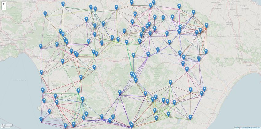
Finally, we tested a network of detectors to measure the time between the first detection
and the time when the message was received in the network. We built the test network
using 20 instances of the node code running in a single machine, each instance connected to
10 random neighbors (partial mesh). Figure 9 represents the network. The test machine is a
Dell XPS 15, 6-Core i7 @ 2.20GHz. Delays of 5 to 205 milliseconds were randomly injected
into the packet transmissions to emulate the network latency. We performed six tests using
the same topology but different points of origin for EEWs.
Figure 9. Detector network used in simulations. Lines between detectors represents connections.
Detectors are placed in a random pattern. Tile images by OpenStreetMap [18].
As shown in Figure 10, in all but two test, the EEW reached every node of the network
in less than 450 milliseconds (including simulated network delay).
Detectors warned since the first EQ detection
100
Test #1
Test #2
80 Test #3
Test #4
Test #5
Detectors warned
60 Test #6
Test #7
40
20
0
0 100 200 300 400 500 600
Time (ms)
Figure 10. Number of detectors warned since the first detection on the source node. Note that the number
of detectors is sampled each 10 ms. The y axis represent the cumulative number of detectors alerted.Information 2022, 13, 195 13 of 15
Limits
In this work, we did not address the security of the network. This area has multiple
aspects, mainly related to the trust in early warnings from neighbors’ sensors. Today, any
byzantine probe in the network can cause a false alarm by sending an alert with a signal that
resembles an earthquake wave (downloadable from public datasets). A byzantine detector
can even send an earthquake early warning. We originally designed the protocol message
so that a signal could be sent together with the EEW as a primary security measure: We
planned to check that the signal attached to the EEW was triggering an EEW by replicating
the detection on each detector. However, we did not clearly define or implement this part
at this time, so we omitted this from the proposal, and it constitutes future work.
Another limit is that we did not address the problem of setting up a secure transmission
between peers. In the prototype, we implemented a plain-text protocol in which attackers
can eavesdrop on the message exchange (loss of confidentiality) and even inject or modify
messages. However, this problem can be solved trivially by using widely studied and
deployed protocols such as TLS [19].
It is worth underlining that the accuracy of the detection algorithm plays a central role
in the trust of this system. Users will trust an EEW system with this architecture only if
they receive very low false positives and false negatives EEWs. We are working on this by
allowing different detection algorithms to plug in to compare their accuracy.
We did not consider epicenter location estimation while designing this proposal.
In a dense network, the location of the sensor that detects the earthquake before other
sensors can be considered an approximation of the epicenter. However, the approximation
error depends on how close the sensor is to the real epicenter, the sensor sensitivity, its
physical installation, and several different geophysical characteristics, such as the terrain
composition (which influences quake waves). Further analysis should be conducted on
minimizing the estimation error.
7. Discussion
We described a crowdsensing EEW architecture that moves the computation to the
edge, with detector nodes that probe the environment and process information from nearby
probes to detect earthquakes locally. Our approach tolerates multiple node faults and
partial network disruption and keeps all data locally, enhancing privacy. We described our
proposal’s rationale, explained its architecture, and presented an implementation using
Raspberry, NodeMCU, and the Crowdquake machine learning model.
On-going research on this topic focuses on the security of this architecture and its
implementations. It is essential to find a viable and secure solution to the problem of trust
in peer-to-peer EEW message exchange to use this architecture in crowdsensing networks.
At least the system should resist some byzantine nodes.
We are developing an app that will be integrated into this architecture both as a sensor
and as a “companion app” for IoT sensors. The app is being built using a user-centered
design as we aim to produce an interface that is easy to use. The app will be able to provide
the user with all data from its sensors and monitor them. Thanks to the app, we will be able
to test the system from the point of view of a typical user, starting from initial configuration,
to maintenance, to data access and retrieval.
Another focus of our current research is the implementation of the architecture that
we presented over low-power, long-range radio protocols (LPWAN), such as LoRa. These
wireless protocols are very effective in long-range transmissions and power efficiency com-
pared to Wi-Fi networks. However, they usually lack coordination, so collision-avoidance
algorithms such as water-filling cannot be used (unlike in LoRaWAN, where water-filling
can be implemented in BTS [20] or in the control plane [21]), and we will need to overcome
this limitation. The detection network can be deployed seamlessly from big cities to remote
sites using LPWAN for IoT [14], LTE for smartphones, and FWA/FTTx for others. In
the big cities, the Internet is ubiquitous, while in remote sites, LPWAN can be a low-cost,
low-latency alternative to satellite links.Information 2022, 13, 195 14 of 15
Author Contributions: Project administration, resources, supervision, writing—review and editing:
E.P.; conceptualization, data curation, formal analysis, investigation, methodology, resources, soft-
ware, validation, visualization, writing—original draft, writing—review and editing: E.B. All authors
have read and agreed to the published version of the manuscript.
Funding: This research was funded by the Italian National Institute for Geophysics and Volcanology
(INGV).
Conflicts of Interest: The authors declare no conflict of interest.
Abbreviations
The following abbreviations are used in this manuscript:
BTS Base Transceiver Station
CRNN Convolutional-Recurrent Neural Network
EEW Earthquake Early Warning
FWA Fixed-Wireless Access
GPIO General Purposes Input/Output
GPU Graphics Processing Unit
HA High availability
IoT Internet-of-Things
JMA Japan Meteorological Agency
LPWAN Low Power Wide Area Network
MEMS Micro-Electro-Mechanical Systems
MQTT Message Queuing Telemetry Transport
SDK Software-Development Kit
SPoF Single point of failure
TLS Transport Layer Security
UCD User-Centered Design
References
1. Hoshiba, M.; Kamigaichi, O.; Saito, M.; Tsukada, S.; Hamada, N. Earthquake early warning starts nationwide in Japan. EOS
Trans. Am. Geophys. Union 2008, 89, 73–74. [CrossRef]
2. Allen, R.M.; Kong, Q.; Martin-Short, R. The MyShake platform: A global vision for earthquake early warning. Pure Appl. Geophys.
2020, 177, 1699–1712. [CrossRef]
3. Zhang, L.; Pathak, P.H.; Wu, M.; Zhao, Y.; Mohapatra, P. Accelword: Energy efficient hotword detection through accelerometer.
In Proceedings of the 13th Annual International Conference on Mobile Systems, Applications, and Services, Florence, Italy,
18–22 May 2015; pp. 301–315.
4. Tsitsiklis, J. Decentralized Detection-Advances in Syatis—Tical Signal Processing; JAI: Greenwich, CT, USA, 1990.
5. Faulkner, M.; Liu, A.H.; Krause, A. A fresh perspective: Learning to sparsify for detection in massive noisy sensor networks.
In Proceedings of the 12th International Conference on Information Processing in Sensor Networks, Philadelphia, PA, USA,
8–11 April 2013; pp. 7–18.
6. Cochran, E.S.; Lawrence, J.F.; Christensen, C.; Jakka, R.S. The quake-catcher network: Citizen science expanding seismic horizons.
Seismol. Res. Lett. 2009, 80, 26–30. [CrossRef]
7. Kong, Q.; Allen, R.M.; Schreier, L.; Kwon, Y.W. MyShake: A smartphone seismic network for earthquake early warning and
beyond. Sci. Adv. 2016, 2, e1501055. [CrossRef] [PubMed]
8. Finazzi, F. The earthquake network project: Toward a crowdsourced smartphone-based earthquake early warning system. Bull.
Seismol. Soc. Am. 2016, 106, 1088–1099. [CrossRef]
9. Panizzi, E. The seismocloud app: Your smartphone as a seismometer. In Proceedings of the International Working Conference on
Advanced Visual Interfaces, Bari, Italy, 7–10 June 2016; pp. 336–337.
10. Huang, X.; Lee, J.; Kwon, Y.W.; Lee, C.H. CrowdQuake: A networked system of low-cost sensors for earthquake detection via
deep learning. In Proceedings of the 26th ACM SIGKDD International Conference on Knowledge Discovery & Data Mining,
Virtual Event, 6–10 July 2020; pp. 3261–3271.
11. Wu, A.; Lee, J.; Khan, I.; Kwon, Y.W. CrowdQuake+: Data-driven Earthquake Early Warning via IoT and Deep Learning.
In Proceedings of the 2021 IEEE International Conference on Big Data (Big Data), Orlando, FL, USA, 15–18 December 2021;
pp. 2068–2075.
12. Fischer, J.; Kühnlenz, F.; Ahrens, K.; Eveslage, I. Model-based Development of Self-organizing Earthquake Early Warning Systems.
Simul. Notes Eur. 2009, 19, 9–20. [CrossRef]Information 2022, 13, 195 15 of 15
13. Lee, J.; Khan, I.; Choi, S.; Kwon, Y.W. A smart iot device for detecting and responding to earthquakes. Electronics 2019, 8, 1546.
[CrossRef]
14. Boccadoro, P.; Montaruli, B.; Grieco, L.A. Quakesense, a LoRa-compliant earthquake monitoring open system. In Proceedings of
the 2019 IEEE/ACM 23rd International Symposium on Distributed Simulation and Real Time Applications (DS-RT), Cosenza,
Italy, 7–9 October 2019; pp. 1–8.
15. Anderson, D.P. Boinc: A system for public-resource computing and storage. In Proceedings of the Fifth IEEE/ACM International
Workshop on Grid Computing, Pittsburgh, PA, USA, 8 November 2004; pp. 4–10.
16. Crisnapati, P.N.; Wulaning, P.D.; Hendrawan, I.N.R.; Bandanagara, A.A.K.B. Earthquake Damage Intensity Scaling System based
on Raspberry Pi and Arduino Uno. In Proceedings of the 2018 6th International Conference on Cyber and IT Service Management
(CITSM), Parapat, Indonesia, 7–9 August 2018; pp. 1–4. [CrossRef]
17. Kumar, A.; Sharma, A. Internet of Life (IOL). In Proceedings of the International Conference of Advance Research and Innovation
(ICARI-2015), Istanbul, Turkey, 27–31 July 2015.
18. OpenStreetMap Contributors. Planet Dump. 2017. Available online: https://planet.osm.org and https://www.openstreetmap.
org (accessed on 2 February 2022).
19. Dierks, T.; Allen, C. The TLS Protocol Version 1.0; RFC 2246; IETF: Fremont, CA, USA, 1999.
20. Cuomo, F.; Campo, M.; Caponi, A.; Bianchi, G.; Rossini, G.; Pisani, P. EXPLoRa: Extending the performance of LoRa by suitable
spreading factor allocations. In Proceedings of the 2017 IEEE 13th International Conference on Wireless and Mobile Computing,
Networking and Communications (WiMob), Rome, Italy, 9–11 October 2017; pp. 1–8.
21. Cuomo, F.; Campo, M.; Bassetti, E.; Cartella, L.; Sole, F.; Bianchi, G. Adaptive mitigation of the Air-Time pressure in LoRa
multi-gateway architectures. In Proceedings of the European Wireless 2018; 24th European Wireless Conference, Catania, Italy,
2–4 May 2018; pp. 1–6.You can also read