DATASHEET gen4-Internet of Displays Series - 4D Systems
←
→
Page content transcription
If your browser does not render page correctly, please read the page content below

gen4-Internet of Displays Series

DATASHEET
DOCUMENT DATE: 19th August 2020
DOCUMENT REVISION: 1.4

gen4-IoD-24T (Resistive touch)
gen4-IoD-28T (Resistive touch)
gen4-IoD-32T (Resistive touch)

                                                                  Uncontrolled Copy when printed or downloaded.
                                                               Please refer to the 4D Systems website for the latest
                                                                                          Revision of this document

                             W W W . 4 D S Y S T E M S . C O M . A U
Table of Contents

Table of Contents
    1.    Description ...................................................................................................................4

    2.    Features .......................................................................................................................4

    3.    Hardware Overview ......................................................................................................5

    4.    Hardware Interface – Pins .............................................................................................6
            4.1.         Serial Ports – TTL Level Serial ........................................................................................ 6
            4.2.         System Pins .................................................................................................................... 6
            4.3.         SPI – (Used internally).................................................................................................... 6

    5.    ESP8266 SoC .................................................................................................................7

    6.    SD/SDHC Memory Cards ...............................................................................................7

    7.    FCC Cable .....................................................................................................................7

    8.    Application PCB Support ...............................................................................................7

    9.    Display/Module Precautions .........................................................................................8

    10. Hardware Tools ............................................................................................................8
            10.1.        Programming Adaptor ................................................................................................... 8

    11. Internal / External Antenna...........................................................................................9

    12. FCC Cable Orientation ...................................................................................................9

    13. Programming the IoD .................................................................................................. 10
            13.1.        Arduino IDE .................................................................................................................... 10
            13.2.        Additional Libraries ........................................................................................................ 10
            13.3.        4D Systems – Workshop 4 IDE ....................................................................................... 11

    14. Starter Kit ................................................................................................................... 12

    15. Display Module Numbers ............................................................................................ 12

    16. Mechanical Details – gen4-IoD 2.4’’ ............................................................................. 13

    17. Mechanical Details – gen4-IoD 2.8’’ ............................................................................. 14

    18. Mechanical Details – gen4-IoD 3.2 ............................................................................... 15

    19. Mechanical Details - 4D – Universal Programming Adaptor .......................................... 16

    20. Schematic Details – gen4-IoD Display .......................................................................... 17

    21. Schematic Details - 4D – Universal Programming Adaptor ............................................ 18

gen4-IoD-24T/28T/32T                                                Page 2 of 22                                             www.4dsystems.com.au
Table of Contents

    22. Specifications ............................................................................................................. 19

    23. Hardware Revision History .......................................................................................... 21

    24. Datasheet Revision History ......................................................................................... 21

    25. Legal Notice ................................................................................................................ 22

    26. Contact Information ................................................................................................... 22

gen4-IoD-24T/28T/32T                                         Page 3 of 22                                   www.4dsystems.com.au
gen4-Internet of Displays Series

1. Description                                                 2. Features
The gen4-IoD (Internet of Displays) series of is part of       • Powerful Intelligent LCD-TFT display module
the latest gen4 Range of modules Designed and                    powered by the Espressif ESP8266 SoC.
Manufactured by 4D Systems.                                    • 320 x 240 Resolution, RGB 65K true to life colours,
                                                                 TFT Screen with integrated 4-wire Resistive Touch
The gen4 series was designed specifically for ease of            Panel.
integration and use, with careful consideration for
space requirements and functionality.                          • Built in WiFi suitable for ‘Internet of things’
                                                                 applications.
This specific gen4 module features a 2.4”, 2.8” or a           • 802.11 b/g/n/e/i support
3.2” colour TFT LCD display, with Resistive Touch. It is
powered by the WiFi enabled ESP8266, which offers              • Integrated TCP/IP protocol stack
an array of functionality and options for any Designer         • WiFi 2.4 GHz, supporting WPA/WPA2 and
/ Integrator / User.                                             WEP/TKIP/AES, along with STA/AP/STA+AP/P2P
                                                                 operation modes
The gen4-IoD range can be easily programmed using
4D Systems Workshop4 or the Arduino IDE installed              • 4Mbit (512kb) of Flash memory (modules produced
with the ESP8266 core.                                           before July 2020) or 16Mbit (2MB) of Flash memory
                                                                 (modules products July 2020 or after) for User
The feature rich 4D Systems GFX4d library enables                Application Code and Data.
speedy development of applications by providing                • 128Kb of SRAM of which 80kb is available for the
extensive primitive graphics functions, enhanced                 User.
graphics via Workshop4, SD card and touch routines,
integrated into a single library.                              • 10pin FPC connection, for all signals, power,
                                                                 communications and programming.
The on-board SD card socket enables the use of FAT16           • On-board latch type microSD memory card
or FAT32 formatted cards for extensive storage                   connector for multimedia storage and data logging
capabilities.                                                    purposes.
                                                               • DOS compatible file access (FAT16 or FAT32 format).
The gen4-IoD series of Integrated Display Modules
features a 10 pin ZIF socket, designed for a 10 pin FFC        • Display full colour images, animations, and icons.
cable, for easy and simple connection to an application
                                                               • 4.0V to 5.5V range operation (single supply). A
or mother board, or for connecting to accessory
                                                                 1Amp+ supply is highly recommended for stability.
boards for a range of functionality advancements.
                                                               • Module dimensions:
The gen4 series of modules has been designed to                  (2.4”) 78.4 x 44.8 x 7.2mm.
minimise the impact of display related circuitry, and            (2.8”) 87.3 x 52.1 x 7.3mm.
provide a platform suitable for integration into a               (3.2”) 95.7 x 57.1 x 7.5mm.
product. Application boards can sit flush on the back          • Weighing: ~26 g (2.4”), ~36 g (2.8”), ~44 g (3.2”),
of the gen4 if required, as the display related
electronics sit inside the plastic mounting base, leaving      • 4x mounting tabs with 3.2mm holes for mechanical
the application board surface clear for User circuitry.          mounting using M3 screws.
                                                               • RoHS, REACH and CE compliant.
More information on the Espressif ESP8266 SoC can be
found on the Espressif website http://espressif.com,
and from the ESP8266EX SoC datasheet itself:                   NOTE: Arduino is a trademark of Arduino Team, and all
http://www.espressif.com/sites/default/files/docum             references to the word “Arduino” or use of its
entation/0a-esp8266ex_datasheet_en.pdf                         logo/marks are strictly in reference to the Arduino
                                                               product, and how this product is compatible with the
                                                               aspect of the product but is not associated with the
                                                               Arduino Team in anyway.
                                                               ESP8266 / ESP8266EX are products made by Espressif.
                                                               4D Systems is not associated with Espressif in anyway,
                                                               other than utilising their product inside of ours.

gen4-IoD-24T/28T/32T                                 Page 4 of 22                        www.4dsystems.com.au
gen4-Internet of Displays Series

 3. Hardware Overview

Latch Type                                                                                2.4”, 2.8” or 3.2” TFT LCD
microSD Socket                                                                            with Resistive Touch

  AR1021                                                                   USER I/O – 10 way ZIF Socket
  Resistive Touch                                                          0.5mm pitch Upper Contact
  Controller                                                               5.5mm wide FPC Cable
                      ESP8266 SoC
                                            PIN 10         PIN 1            Ceramic chip antenna, and
   4Mbit Flash
                                                                            U.FL external antenna connector
   Memory for the
   ESP8266

                                     USER I/O - 10 Way FPC
  Pin      Conditions        I/O                                   Description
   1           GND            P     Supply Ground.
   2           GND            P     Supply Ground.
                                    Master Reset signal. Internally pulled up to 3.3V via a 10K resistor. An
                                    active Low pulse greater than 2 micro-seconds will reset the module. If
                                    the module needs to be reset externally, only use open collector type
   3          RESET            I
                                    circuits. This pin is not driven low by any internal conditions. The host
                                    should control this pin via one of its port pins using an open
                                    collector/drain arrangement.
   4          GPIO0          I/O    I/O pin. This pin is used for backlight control and flash programming
                                    Asynchronous Serial Receive pin, TTL level. Connect this pin to the
                                    Transmit (Tx) signal of other serial devices. Used in conjunction with the
   5             RX            I
                                    TX pin for programming this module. This pin is tolerant up to 3.3V
                                    levels.
                                    Asynchronous Serial Transmit pin, TTL level. Connect this pin to the
   6             TX           O     Receive (Rx) signal of other serial devices. Used in conjunction with the
                                    RX pin for programming this module. This pin outputs 3.3V levels.
   7           GND            P     Supply Ground.
                                    I/O pin. Can be used as digital input or output. Can also be used for PWM
   8         GPIO16          I/O    and 1-wire device interfacing. This pin is available to the user. This pin is
                                    tolerant up to 3.3v levels.
   9          5V IN           P     Main Voltage Supply +ve input pin. Range is 4.0V to 5.5V, nominal 5.0V.
   10         5V IN           P     Main Voltage Supply +ve input pin. Range is 4.0V to 5.5V, nominal 5.0V.

 I = Input, O = Output, P = Power

 gen4-IoD-24T/28T/32T                          Page 5 of 22                            www.4dsystems.com.au
gen4-Internet of Displays Series

4. Hardware Interface – Pins                                       4.2. System Pins
This section describes in detail the hardware interface            +5V IN (Module Voltage Input)
pins of the device.                                                Module supply voltage input pins. Both of these pins
                                                                   should be connected to a stable supply voltage in the
                                                                   range of 4.0 Volts to 5.5 Volts DC. Nominal operating
4.1. Serial Ports – TTL Level Serial                               voltage is 5.0 Volts. Note backlight brightness will be
                                                                   dimmer for voltages under 5.0V.

The ESP8266 Processor has a hardware asynchronous                  GND (Module Ground)
serial ports that can be accessed via the 10 way FPC or            Device ground pins. Both pins should be connected to
via the gen4-Iod-programmer. The serial port can be                ground.
used to communicate with external serial devices.
The primary features are:                                          RESET (Module Master Reset)
• Full-Duplex 8 bit data transmission and reception.               Module Master Reset pin. An active low pulse of
                                                                   greater than 2μs will reset the module. Internally
•    Data format: 8 bits, No Parity, 1 Stop bit.                   pulled up to 3.3V via a 10K resistor. Only use open
•    Independent Baud rates from 300 baud up to                    collector type circuits to reset the device if an external
     921600 baud.                                                  reset is required.
•    Single byte transmits and receives or a fully
     buffered service. The buffered service feature                GPIO0 (Backlight/Flash)
     runs in the background capturing and buffering                This pin is dedicated to both backlight control and the
     serial data without the user application having to            Flashing of the IoD program memory via the
     constantly poll any of the serial ports. This frees           programming software. This pin must be left floating
     up the application to service other tasks.                    at power-up to enable the ESP8266 to boot correctly.
                                                                   If GPIO0 is set to be an input in User code once the
A single byte serial transmission consists of the start            ESP8266 has booted, then this pin could be controlled
bit, 8-bits of data followed by the stop bit. The start bit        externally to adjust backlight brightness using PWM or
is always 0, while a stop bit is always 1. The LSB (Least          simple on/off control. Else, the backlight can be
Significant Bit, Bit 0) is sent out first following the start      controlled from the ESP8266 itself, with appropriate
bit. Figure below shows a single byte transmission                 User code.
timing diagram.
                                                                   GPIO16 (User GPIO)
                                                                   Input/Output available to the user. This pin can be
                                                                   used as a digital input or digital output to connect to
                                                                   sensors, relays etc. This pin can also be used for ‘1-
                                                                   wire’ protocol devices and as a PWM output.

                                                                   4.3. SPI – (Used internally)
The serial port is also the primary interface for User             There is 1 hardware SPI channel (HWSPI) which is
program downloads, and configuration via the IDE.                  dedicated to drive the screen, SD card and Resistive
                                                                   Touch. The SPI channel can communicate at speeds up
                                                                   to 80Mhz. The SPI channel is Master only, and cannot
                                                                   be configured to be slave at this time, nor is it available
                                                                   for the User externally.

                                                                   Note: The SPI channel (HWSPI) is dedicated to
                                                                   memory card, screen and touch controller. The HWSPI
                                                                   channel cannot be reconfigured for alternate uses.

gen4-IoD-24T/28T/32T                                     Page 6 of 22                          www.4dsystems.com.au
gen4-Internet of Displays Series

5. ESP8266 SoC                                                8. Application PCB Support
The module is designed around the ESP8266 SoC from            The gen4-IoD Display Module Series is designed to
Espressif.                                                    accommodate a range of applications, and therefore is
                                                              suited for those wanting to make a customised
The ESP8266 is a 32bit RISC Microcontroller with built        module, without the need for piggy-back or daughter
in WiFi controller, and GPIO capability, however most         boards mounted on headers.
GPIO are utilised for on board features, such as the TFT
LCD, Touch Controller and microSD card.                       On the back of the gen4 module, the display related
                                                              circuitry will be found, which is recessed into the
The TFT-LCD display interfaces to the ESP8266 using           plastic. The level of the plastic on the back of the gen4
SPI, along with the microSD card and touch controller.        module is higher than the tallest component on the
This enables high speed transfers for these                   display circuit PCB, meaning an Application PCB can be
peripherals, providing fast graphics, fast SD card            mounted on the back of the gen4, without affecting
access and responsive touch control.                          the display related circuitry. An application board can
                                                              be made it fit inside the corner notches of the gen4
Powerful graphics, text, image, animation, internet           plastics.
access and countless more features are available to
the user via the 4D Systems GFX4d library and 4D
Systems Workshop 4 IDE. Alternatively, the Arduino
IDE can be used, and the User is able to write
drivers/software for the module as they require.

6. SD/SDHC Memory Cards
The gen4-IoD module supports microSD memory cards
via the on-board latch type micro-SD connector.

The memory card is used for
all multimedia file retrieval
such as images, animations
and data files.
The memory card can also be
used as general purpose                                                       Pictured: gen4-IoD-24T
storage for data logging applications.
                                                              The 10 way FFC flex cable can come out of the gen4
Support is available for off-the-shelf high capacity HC       display module and into the application board, either
memory cards (4GB and above). Memory cards up to              by coming up through a slot in the Users application
32GB is size can be used, as FAT16 or FAT32, however          board, or by travelling along the channel in the gen4
it must be noted that only a portion of this can be           plastic’s and emerging at the edge of the display
utilised by the FAT16 file system.                            module then curving around into the Users application
                                                              board.

7. FCC Cable                                                  The microSD socket is a latch type, so it is accessible
                                                              from the top, rather than a push/push or push/pull
                                                              style which is accessible from the side. A slot can be
The Standard FFC cable supplied has the following
                                                              routed in the Users application board so this is
specifications:
                                                              accessible, if required.
•   10 Pin Flexible Flat Cable, 150mm Long, 0.5mm
                                                              If an external antenna is being used, the antenna can
    (0.02") pitch
                                                              also run down the plastic channel next to the 10 way
•   Cable Type: AWM 20624 80C 60V VW-1
                                                              FFC cable, not affecting the Users Application Board, if
•   Heat Resistance 80 Degrees Celsius
                                                              fitted.
•   Connections on the opposite side at each end
    (Type B)

gen4-IoD-24T/28T/32T                                Page 7 of 22                         www.4dsystems.com.au
gen4-Internet of Displays Series

9. Display/Module Precautions                                     10. Hardware Tools
•   Avoid having to display the same image/object on              The following hardware tools are required for full
    the screen for lengthy periods of time. This can              control of the gen4 IoD Display Modules.
    cause a burn-in which is a common problem with
    all types of display technologies. Blank the screen           10.1. Programming Adaptor
    after a while or dim it very low by adjusting the
    contrast. Better still; implement a screen saver              The 4D Systems Universal Programming Adaptor (4D-
    feature.                                                      UPA) is an essential hardware tool to program,
                                                                  customise and test the gen4-IoD Display Module.
•   Moisture and water can damage the display.
    Moisture on the surface of a powered display                  The 4D - UPA is used to program the IoD via
    should not cause any problems, however if water               Workshop4 and the Arduino IDE. It even serves as an
    is to enter the display either from the front or              interface for communicating serial data to the PC.
    from the rear, or come in contact with the PCB,
    damage will certainly occur. Wipe off any
    moisture gently or let the display dry before
    usage. If using this display module in an
    environment where it can get wet, ensure an
    appropriate enclosure is used.

•   Dirt from fingerprint oil and fat can easily stain the
    surface of the display. Gently wipe off any stains
    with a soft lint-free cloth.

•   The performance of the display will degrade
    under high temperature and humidity. Avoid such
    conditions when storing.

•   Do not tamper with the display flex cable that is
    connected to the control board. This may affect
    the connection between the display and the
    driving circuitry and cause failure.

•   Displays are susceptible to mechanical shock and
    any force exerted on the module may result in
    deformed zebra stripes, a cracked display cell and
    broken backlight

•   Always use the mounting holes on the module's
    corner plates to mount the display where
    possible.
                                                                  The 4D - UPA is available from 4D Systems website,
•   Display modules have a finite life, which is                  www.4dsystems.com.au
    typically dictated by the display itself, more
    specifically the backlight. The backlight contains            Please note, the 4D-UPA can be used as a simple
    LED’s, which fade over time. In the Specifications            interface to power the IoD or to connect to other serial
    section is a figure for the typical life of the display,      devices.
    and the criteria are listed.
                                                                  The 4D - UPA features an Auto-Reset circuit (credit –
•   Resistive Touch model features a touch sensitive              NodeMCU), but also features Reset and Flash buttons,
    film over the display which is sensitive to                   for flexibility.
    pressure. Take note when mounting the display
    module in an enclosure that pressure is not                   Alternatively, other programming devices could be
    applied to the surface of the display by the                  used, including programming from a host controller.
    enclosure, or false touches will occur, or the touch          Please refer to the ESP8266 datasheet for more
    will simply not function at all.                              options on programming this SoC.

gen4-IoD-24T/28T/32T                                    Page 8 of 22                        www.4dsystems.com.au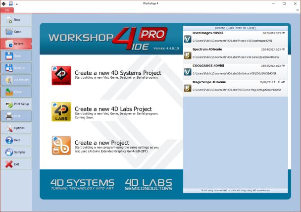
gen4-Internet of Displays Series

11. Internal / External Antenna                              12. FCC Cable Orientation
The gen4-IoD is capable of using either the on-board         The 10-way FFC cable connects to the gen4-IoD and
ceramic chip antenna, or using an external antenna           the 4D-UPA, the same way. Both feature Bottom
connecting using the U.FL connector on the PCB.              Contact FFC connectors, meaning the FFC cable
                                                             connects into the board with the contacts facing
By default, the on-board ceramic chip antenna is used,       down, blue side facing up.
and SB2 (Solder Bridge 2) is shorted, enabling contact
of the LBA pin to the ceramic chip antenna.

If the external antenna is desired instead, SB1 (Solder
Bridge 1) needs to be shorted, using a small blob of
solder via a soldering iron, and SB2 needs to be de-
soldered. SB2 ‘can’ be left connected if required,
however WiFi performance may be impeded to some
degree, due to two antennas being connected at the
same time, however it should still work in most
situations.

gen4-IoD-24T/28T/32T                               Page 9 of 22                     www.4dsystems.com.au
gen4-Internet of Displays Series

13. Programming the IoD
There are two IDE’s available to program the IoD.
Using the Arduino IDE, or using the 4D Systems
Workshop4 IDE.

Using the Workshop4 IDE provides additional
graphical benefits over using the Arduino IDE,
however the Worskhop4 IDE is only Windows based
(unless via a Virtual Machine).                                 Once it loads, scroll down to the bottom, and you
                                                                should see a listing for esp8266. Click on it, and then
If using the Workshop4 IDE, Workshop4 installation              on install, and install the latest version.
will call the Arduino IDE in the background for
programming the board (handled automatically and
invisibly). Some minor setup is required to install the
board into the Arduino IDE, using the Board Manager
and installing the JSON file. See the following section.

If the Workshop4 IDE is not going to be used at all,            Once this has been completed, click Close, and then
then the IoD board needs to be added into the Arduino           shut down the Arduino IDE.
IDE in the same way, using the Arduino Board
Manager. More details below.                                    The Arduino IDE should then be set up to start using
                                                                the gen4-IoD.

13.1. Arduino IDE                                               NOTE: For advanced users, the Github repository for
                                                                the Arduino esp8266 core (non-stable version), is not
The gen4-IoD is Arduino IDE compatible. The IoD can             classed as being stable by Espressif. Use at your own
be directly programmed via Arduino IDE like any other           risk.
ESP8266/Arduino module.
                                                                https://github.com/esp8266/Arduino
The gen4-IoD must be added to the Arduino IDE. This
is typically done using the Boards Manager.                     Follow the instructions on their Github readme.
Advanced users who wish to use the Github main
repository are welcome to, which also supports the              2.7.4 release of this Library included support for the
gen4-IoD, however is not classed as Stable by the               gen4-IoD Modules with 2MB of Flash, along with the
ESP8266 community so should be used with caution.               512KB option which was there in previous versions.

The easiest way to install the gen4-IoD into the                NOTE: The ESP8266 Core is not maintained or created
Arduino IDE, is by installing the Stable release JSON file      by 4D Systems. It belongs to esp8266.com
provided by the ESP8266 community. This is done by
starting up the Arduino IDE, going File, Preferences,
and entering the following line into the ‘Additional            13.2. Additional Libraries
Boards Manager URLs’ field. If you already have a
listing in there, simply add a comma after the last one,        Check out the GFX4d library from the 4D Systems
and paste this new URL in at the end:                           github page: https://github.com/4dsystems

http://arduino.esp8266.com/stable/packa                         This contains the library specifically for the gen4-IoD
ge_esp8266com_index.json                                        and some demo applications.

Click OK on the preferences window to close it.                 This library can be downloaded and added to the
                                                                Arduino IDE, like any normal library.
Go up to Tools, Board, and click on Board Manager.
                                                                Navigate to https://github.com/4dsystems/GFX4d
                                                                and download the repository, using the
                                                                download/clone button. Save the zip file to your PC.

gen4-IoD-24T/28T/32T                                  Page 10 of 22                        www.4dsystems.com.au
gen4-Internet of Displays Series
Open the Arduino IDE, and go to Sketch – Include
Library – Add Zip Library
The library will then be installed, and will be available
for you to use. There are example applications Note: Workshop requires the Arduino IDE to be
available in the examples folder. installed as Workshop calls the Arduino IDE for
compiling the Arduino sketches. The Arduino IDE
however is not required to be opened or modified to
13.3. 4D Systems – Workshop 4 IDE program the gen4-IoD, once it has been set up. Please
follow the steps found in the previous section to install
Workshop 4 is a comprehensive software IDE that and add the gen4-IoD to the Arduino IDE, prior to
provides an integrated software development installing the Workshop4 IDE.
platform for all 4D Systems Intelligent Display
Modules, including the IoD.
Workshop4 allows rapid development of applications,
and on the gen4- IoD can take full advantage of the
available extended graphics functions.
The Workshop IDE can create/edit Arduino code and
verify/compile and then load the code into the IoD’s
ESP8266 processor, without having to use the Arduino
IDE directly. It makes it possible to create both simple
and complex graphical user interfaces.
When Workshop4 is started, it presents the User with
a screen to start a new project, or to load a project.
Upon selecting to start a new project, another screen
is displayed, presenting the wide range of 4D Systems
products available to be programmed or configured by
the Workshop4 IDE, of which there is the gen4-IoD-
24T, gen4-IoD-28T and gen4-IoD-32T.
The Workshop4 IDE can be used to program the gen4-
IoD, just as the Arduino IDE does. This is possible due
to the integration of the Arduino compiler via the
Arduino IDE, which allows Arduino sketches to be
written and compiled from within the Workshop4 IDE,
which then provides WS4 the benefit of adding
graphical widgets and features to the gen4-IoD, which
would otherwise not be available when using the
Arduino IDE.
If you use the Workshop4 IDE, you can program the
gen4-IoD module and have the opportunity to create
graphics which you can call using Arduino code via the
GFX4d library. Many options are possible.
gen4-IoD-24T/28T/32T Page 11 of 22 www.4dsystems.com.augen4-Internet of Displays Series
14. Starter Kit 15. Display Module Numbers
4D Systems highly recommends all first-time buyers of The following is a breakdown on the part
4D Systems’ displays, to purchase the Starter Kit when numbers and what they mean.
purchasing their first 4D Systems display solution.
Example:
The Starter Kit provides all the hardware that is
gen4-IoD-24T
required to get the User up and running.
gen4-IoD-28T
Not all development environments and features will gen4-IoD-32T
be needed by every User. However, by purchasing the
display solution in a Starter Kit allows you to take full gen4 - gen4 Display Family
advantage of all of the features of the 4D Systems IoD - IoD (Internet of Displays) Range
Display Solution and try out each of the 4D Woskshop4 24 - Display size (2.4”)
Environments prior to settling with the preferred 28 - Display size (2.8”)
feature-set. 32 - Display size (3.2”)
T - Resistive Touch
Starter Kits typically include:
• gen4 IoD Display Module
• 4D-UPA
• 150mm 10-way FFC cable for connecting
gen4 display to 4D - UPA
• 4GB micro-SD Card
Please refer to the 4D Systems website for current
components included in the Starter Kit, if available.
Simply select the Starter Kit option when purchasing
the chosen display module on the 4D Systems
shopping cart, or from your local distributor.
gen4-IoD-24T/28T/32T Page 12 of 22 www.4dsystems.com.augen4-Internet of Displays Series 16. Mechanical Details – gen4-IoD 2.4’’ gen4-IoD-24T/28T/32T Page 13 of 22 www.4dsystems.com.au
gen4-Internet of Displays Series

17. Mechanical Details – gen4-IoD 2.8’’

gen4-IoD-24T/28T/32T                      Page 14 of 22         www.4dsystems.com.au
gen4-Internet of Displays Series

18. Mechanical Details – gen4-IoD 3.2

gen4-IoD-24T/28T/32T                    Page 15 of 22         www.4dsystems.com.au
gen4-Internet of Displays Series

19. Mechanical Details - 4D – Universal Programming Adaptor

gen4-IoD-24T/28T/32T                             Page 16 of 22         www.4dsystems.com.au
gen4-Internet of Displays Series

20. Schematic Details – gen4-IoD Display

gen4-IoD-24T/28T/32T                       Page 17 of 22         www.4dsystems.com.au
gen4-Internet of Displays Series

21. Schematic Details - 4D – Universal Programming Adaptor

gen4-IoD-24T/28T/32T                             Page 18 of 22         www.4dsystems.com.au
gen4-Internet of Displays Series

22. Specifications

                                                    ABSOLUTE MAXIMUM RATINGS
 Operating ambient temperature ................................................................................................... -20°C to +70°C
 Storage temperature .......................................................................................................................... -30°C +80°C
 Voltage on any digital input pin with respect to GND ....................................................................... -0.3V to 6.0V
 Voltage on VCC with respect to GND ................................................................................................. -0.3V to 6.0V
 Maximum current sunk/sourced by any pin .............................................................................................. 12.0mA
 NOTE: Stresses above those listed here may cause permanent damage to the device. This is a stress rating only
 and functional operation of the device at those or any other conditions above those indicated in the
 recommended operation listings of this specification is not implied. Exposure to maximum rating conditions for
 extended periods may affect device reliability.
 Operating ambient temperature ................................................................................................... -20°C to +70°C

                                       RECOMMENDED OPERATING CONDITIONS
         Parameter                                       Conditions                                 Min            Typ           Max            Units
  Supply Voltage (VCC)                 Stable external supply required                               4.0            5.0           5.5              V
  Operating Temperature                                                                              -10             --           +60              °C
  Input Low Voltage                    3.3V, all pins                                                -0.3            --        0.25VCC              V
  Input High Voltage                   GPIO0, GPIO16, and RX Pins                                  0.7VCC            --           3.3               V
  Output Low Voltage                                                                                  --             --         0.1VCC              V
  Output High Voltage                                                                              0.8VCC            --            --               V

                   GLOBAL CHARACTERISTICS BASED ON OPERATING CONDITIONS
            Parameter                                       Conditions                              Min            Typ           Max            Units
                                            gen4-IoD-24T – Average, not Peak                           --          200              --            mA
  Supply Current (ICC)                      gen4-IoD-28T – Average, not Peak                           --          200              --            mA
                                            gen4-IoD-32T – Average, not Peak                           --          220              --            mA
                                            Hours of operation, measured to
  Display Endurance                         when display is 50% original                           30000             --             --              H
                                            brightness
                                            Number of touches/hits with a
                                            12.5mm tip at a rate of 2x per                             --           1M              --         Touches
  Touch Screen Endurance                    second with 250gf force
  (Resistive Touch)                         Slide stylus on screen, 100gf force,
                                            60mm/s speed with a 0.8mm                                  --         100K              --           Slides
                                            polyacetal tip stylus pen
  Touch Screen Transparency                 Resistive Touch                                           82             --             --             %
  Touch Screen Operational                  Only use Finger or Stylus, do not
                                                                                                      20             --           100              Gf
  Force (Resistive Touch)                   use anything sharp or metal

gen4-IoD-24T/28T/32T                                                Page 19 of 22                                         www.4dsystems.com.au
gen4-Internet of Displays Series
LCD DISPLAY INFORMATION
Parameter Conditions Specification
Display Type TFT Transmissive LCD
gen4-IoD-24T 2.4” Diagonal
Display Size gen4-IoD-28T 2.8” Diagonal
gen4-IoD-32T 3.2” Diagonal
Display Resolution 240 x 320 (Portrait Viewing)
gen4-IoD-24T 182 cd/m2
Display Brightness gen4-IoD-28T 140 cd/m2
gen4-IoD-32T 160 cd/m2
Typical (2.4”, 2.8”) 250:1
Display Contrast Ratio
Typical (3.2”) 500:1
Above Centre 35 Degrees
Below Centre 55 Degrees
Display Viewing Angles
Left of Centre 55 Degrees
Right of Centre 55 Degrees
6 o’clock Display
Display Viewing Direction (Optimal viewing is from below when in
Portrait mode)
gen4-IoD-24T 1x4 Parallel LED’s
Display Backlighting gen4-IoD-28T 1x4 Parallel LED’s
gen4-IoD-32T 1x6 Parallel LED’s
gen4-IoD-24T 0.153 x 0.153mm (Square pixels)
Pixel Pitch gen4-IoD-28T 0.18 x 0.18mm (Square pixels)
gen4-IoD-32T 0.2025 x 0.2025mm (Square pixels)
166 DPI/PPI
Number of pixels in 1 row in
Pixel Density 141 DPI/PPI
25.4mm
127 DPI/PPI
gen4-IoD-24T/28T/32T Page 20 of 22 www.4dsystems.com.augen4-Internet of Displays Series
23. Hardware Revision History
Revision Date Description
Number
1.4 29/03/2017 Initial Public Release Version
1.4 (update) 07/07/2020 Same hardware, however modules now shipping with 2MB (16Mbit) of
Flash Memory, instead of 512KB. Allows OTA and more program space
for User code.
24. Datasheet Revision History
Revision Date Description
Number
1.0 12/06/2017 Initial Public Release
1.1 28/02/2019 Format Change, Arduino Instruction update
1.2 05/03/2019 Cosmetic Changes to gen4 Datasheet range
1.3 13/08/2020 Updated information about Flash Memory change (2MB)
1.4 19/08/2020 Update Schematic
gen4-IoD-24T/28T/32T Page 21 of 22 www.4dsystems.com.augen4-Internet of Displays Series
25. Legal Notice
Proprietary Information
The information contained in this document is the property of 4D Systems Pty. Ltd. and may be the subject of patents
pending or granted, and must not be copied or disclosed without prior written permission.
4D Systems endeavours to ensure that the information in this document is correct and fairly stated but does not
accept liability for any error or omission. The development of 4D Systems products and services is continuous and
published information may not be up to date. It is important to check the current position with 4D Systems. 4D
Systems reserves the right to modify, update or makes changes to Specifications or written material without prior
notice at any time.
All trademarks belong to their respective owners and are recognised and acknowledged.
Disclaimer of Warranties & Limitation of Liability
4D Systems makes no warranty, either expressed or implied with respect to any product, and specifically disclaims all
other warranties, including, without limitation, warranties for merchantability, non-infringement and fitness for any
particular purpose.
Information contained in this publication regarding device applications and the like is provided only for your
convenience and may be superseded by updates. It is your responsibility to ensure that your application meets with
your specifications.
Images and graphics used throughout this document are for illustrative purposes only. All images and graphics used
are possible to be displayed on the 4D Systems range of products, however the quality may vary.
In no event shall 4D Systems be liable to the buyer or to any third party for any indirect, incidental, special,
consequential, punitive or exemplary damages (including without limitation lost profits, lost savings, or loss of
business opportunity) arising out of or relating to any product or service provided or to be provided by 4D Systems,
or the use or inability to use the same, even if 4D Systems has been advised of the possibility of such damages.
4D Systems products are not fault tolerant nor designed, manufactured or intended for use or resale as on line control
equipment in hazardous environments requiring fail – safe performance, such as in the operation of nuclear facilities,
aircraft navigation or communication systems, air traffic control, direct life support machines or weapons systems in
which the failure of the product could lead directly to death, personal injury or severe physical or environmental
damage (‘High Risk Activities’). 4D Systems and its suppliers specifically disclaim any expressed or implied warranty
of fitness for High Risk Activities.
Use of 4D Systems’ products and devices in 'High Risk Activities' and in any other application is entirely at the buyer’s
risk, and the buyer agrees to defend, indemnify and hold harmless 4D Systems from any and all damages, claims, suits,
or expenses resulting from such use. No licenses are conveyed, implicitly or otherwise, under any 4D Systems
intellectual property rights.
26. Contact Information
For Technical Support: www.4dsystems.com.au/support
For Sales Support: sales@4dsystems.com.au
Website: www.4dsystems.com.au
Copyright 4D Systems Pty. Ltd. 2000-2020.
gen4-IoD-24T/28T/32T Page 22 of 22 www.4dsystems.com.auYou can also read