CITY OF PORT ST LUCIE FIBER OPTIC NETWORK 2022 - PSL Utilities
←
→
Page content transcription
If your browser does not render page correctly, please read the page content below
2022
City of PSL

PSL US, PW, TE, IT

              CITY OF PORT ST LUCIE

              FIBER OPTIC NETWORK

         Minimum Design Standards and Details

                         V1 2022
City of Port St Lucie               Fiber Optic Network 2022

                                      Table of Contents
    General Conditions                                          2-4

    Definition of Terms                                         4-5

    1.0        Fiber Optic Cable System
           1.1         Fiber Optic Cable                        6-9
           1.2         Fiber Optic Splice Closure             10-11
           1.3         Patch Panels                              11
           1.4         Pigtails                               11-12
           1.5         Pigtail Module                         12-13
           1.6         Pigtail Splice Cassette                   13
           1.7         Patch Cords/Cables                     13-14
           1.8         Splicing Equipment                     14-15
           1.9         OTDR Test Equipment                       15
           1.10        Installation                           16-19
           1.11        Fiber Optic Splicing Requirements      19-21
           1.12        Fiber Optic Termination Requirements   21-22
           1.13        Acceptance Testing                     22-23
           1.14        OSP Multi-Pair Cables                  23-24

    2.0       Network Devices                                 25-28

    3.0       CCTV                                            29-30

    4.0       Guarantee Provisions                              31

    5.0       Conduit                                         32-36

    6.0       Locate Procedures                                 37

    7.0       Locate Tracer Wire                                37

    8.0       Marking Tape                                      38

    9.0       Pull Tape-Mule Tape                               38

    10.0      Cable Route Markers                               38

    11.0      Hub Sites                                         39

    12.0      MDF-indoor facilities-MIS                         40

               Appendix A                                     41-43
               Appendix B – Sample shop drawing cut sheets    44-50
               Appendix C – QPL                               51-58

1     Fiber Optic Specifications                                V1 2022
City of Port St Lucie Fiber Optic Network 2022
DESIGN
The Engineer of Record shall submit, through the City’s Project Manager, the design plans for review to
the City at the 60% and 90% plan review.
The plans should include the fiber optic conduit, pull box, and splice box location. The size of the conduit,
fiber size and type and the type of splice/pull box shall also be included on the drawing. The location of
the trunk line splice shall be shown for review and approval. A proposed splice diagram shall be included.
Midspan splices should be avoided to the trunk line and will need to be approved by the City.
CONSTRUCTION
The contractor shall provide complete installation of conduits and pull boxes including materials,
equipment, labor and documentation, in accordance with these specifications and recognized industry
standards and the system must be fully operational.
SHOP DRAWINGS
Contractor may utilize products on the City of Port St Lucie (CPSL) Qualified Product List (QPL 2022) without
requirement to provide individual project submittals. For each work order or contract with the City, the
Contractor shall submittal a QPL cover sheet noting the items to be implemented on the project. In the
event the Contractor wishes to utilize a product not on the CPSL QPL, the Contractor must submit complete
manufacturer cut sheets, shop drawings or schematics of proposed alternate items.
Contractor to include on product submittal cover sheet, a complete listing of pathway, closure and fiber
optic infrastructure intended for use on the project to include the following:
Conduit
Pull Boxes, Splices Boxes, Splice Vaults, Splice Enclosures, Splice Cabinets
Locate Tracer Wire, Wire Ground Units, Side Leg/Liner Terminators or Switch Boxes
Marking Tape
Pull Tape
Cable Route Markers
Fiber Optic Cable
Splice Closures – Trays
Termination Housings - Components
Fiber Optic Test Procedures
IP Network Devices
Communication Devices
QPL cover sheet or shop drawings shall be approved prior to construction. Any work conducted prior to
approval may result in Contractor expense for approved replacement items.
PULL BOX, SPLICE BOX AND SWEEPS
Conduit plans need to be approved prior to construction. All items identified in the design section shall be
shown on the construction plans. Designer and Contractor to follow Building Industry Consulting Service
International (BICSI) Outside Plant Design Manual (OSP) which follows and implements standards set forth in
the American National Standards Institute/Telecommunications Industry Association/ Electronics Industry
Association (ANSI/TIA/EIA-758) for “telecommunication infrastructure designed of for installation exterior to
buildings.”
2 Fiber Optic Specifications V1 2022
City of Port St Lucie                    Fiber Optic Network 2022
For each CPSL work order, project or contract, Engineer or Contractor shall provide schematics or drawings
including proposed locations of pull and splice boxes with provisions for maximum pull box spacing.

Desired spacing for fiber optic backbone route interim pull box (17” x 30”), interim run single drop splice pull
boxes (24” x 36”) and splice pull boxes (30” x 48”) shall be used at every divided boulevard intersection to
allow for multidirectional conduit and cable routing as well as additional splice access. Standard depth of each
pull box size is 24” unless exiting utilities limit to 18” minimum.

The maximum spacing for backbone routes is 750 linear feet between interim pull boxes and no greater than
2,500 feet between a splice box (24” x 36”) or an intersection splice box (30” x 48”). This establishes a pattern
of one splice box after every four pull boxes (i.e., intersection box, pull box, pull box, pull box, splice box, pull
box, pull box, pull box, intersection box, etc.).

Any pull box designed to be placed in sidewalks, must be a minimum of 24” x 36” x 24”. All pull boxes that are
not in concrete or asphalt sidewalks, shall have a concrete collar placed for protection that shall be a minimum
of 12” length and width outside the pull box dimension with 4” of concrete with mesh for depth.

The Project Design Engineer shall review these default distances which need to be modified for more frequent
splice box placement to facilitate backbone cable connection for certain parcels or routes with more frequent
project connections.

Designs should follow the OSP manual and accommodate ducts entering pull and splice boxes by multiple
means of deployment. The contractor shall provide 45-degree conduit sweeps with long radius consistent
with site conditions or sweep HDPE ducts in gradual bend attempting to avoid 90 degree bends. Conduit
sweeps should be referenced on the construction plans and Contractor must follow must be approved prior to
construction.

SPLICING REQUIREMENTS
The Contractor shall follow approved Project Splice Plans or submit splice diagrams for review and approval
prior to splicing unless responding to an emergency damage restoration. Once the splice diagram is approved,
the CPSL requests the Contractor give three (3) business days’ notice to CPSL for circuit preparation. No
splicing of the fiber optic cable system will be permitted without appropriate qualified City Information
Technology staff approval, by onsite direction or written approval.

All splicing shall be by fusion splice method. Although CPSL staff may not be present for Contractor splice
activity, Contractor to follow manufacturers’ recommended procedures and provide test reports confirming
adherence to ANSI/TIA/EIA and CPSL splice standards where no splice shall exceed .15dB on a bidirectional
average of the OTDR traces or .05 as reflected on a core alignment fusion splice machine.

If Contractor experiences mismatched fiber optic core alignment that may causing excessive losses, Contractor
to follow ANSI/TIA/EIA requiring re-splicing 3 times before acceptance.

AS-BUILT DRAWINGS
As-built drawings shall be provided by means of a secure file transfer method. If included by specific item
inclusion on any CPSL contract, work order or project, all fiber optic pathways and cables are to be asbuilt in
FiberTrak® inclusive of individual fiber allocations in Bentley Communications, GPS recording in ESRI GIS format
inclusive of MySQL GIS referenced datasets of CPSL infrastructure attributes. All GPS points shall be sub-meter
accuracy. All fiber optic asbuilts shall be turned in to the Department who issued the contract and the CPSL
Information Technologies Department for update to the CPSL Master Fiber Optic Network records.

     3     Fiber Optic Specifications                                               V1 2022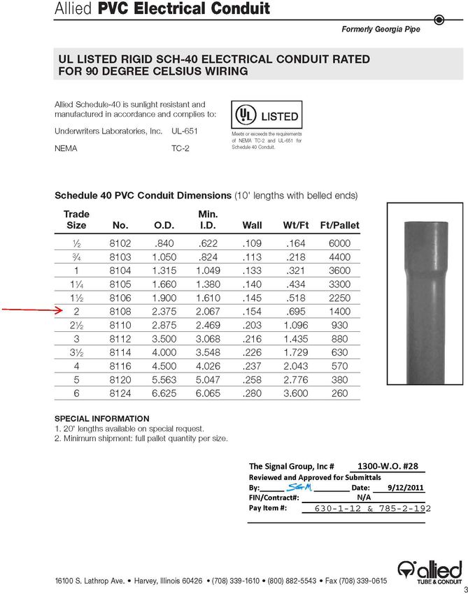
City of Port St Lucie                   Fiber Optic Network 2022
QUALIFIED PRODUCT LIST (QPL)
All material used shall be per the Approved products noted at the end of each appropriate section and
shall be new, unused and of current design and manufacturer. Any materials not found in the Approved
products section shall not be used without the City’s approval.

Contractor to submit product cut sheets, technical data, calculations for materials intended for project use
that are not found in the CPSL QPL to the Project Engineer 30 days before use to allow for review and approval
by the City IT Dept.

All material will be inspected and verified prior to installation. All other applicable specifications will be adhered
to as directed by the City.

DEFINITION of TERMS:

       CITY: The terms “City” and “the City” shall refer to the City of PSL personnel, or their
representatives.

          CONTRACTOR: “Contractor “shall mean an individual, firm, partnership, or corporation, and his,
their or its heirs, executors, administrators, successors and assigns or the lawful agent of any such
individual, firm, partnership, covenanter, or corporation, or his, their or its surety under any contract
bond, constituting one of the principals to the Contract and undertaking to perform the work specified
in the design plans and specifications. Where any pronoun is used as referring to the word “Contractor”,
it shall mean the Contractor as defined herein.

        CITY ONLINE SPECIFICATIONS ACCESS: “Online Access” is available for City of Port St. Lucie
performance specifications and Qualified Products Listing for fiber optics supporting the Public Works,
Traffic Engineering/Operations, Utility Systems, Parks & Recreation and Information Technologies
Department’s available through online City webpage for review at:
        https://utility.cityofpsl.com/media/1590/appendix-c-fiber-optic-standards-and-details.pdf

        ENGINEER OF RECORD: The terms “Engineer” and “Engineer of Record” shall be a duly licensed
and registered engineer in the State of Florida.

         BACKBONE Fiber Optic cable: The term used for any fiber optic cable in City of PSL rights of way the
traverses the entire City in multiple pathways, routes and network architectures supporting multiple City
Departments or other entities for Core Site to Core Site and Core Site to Device Site connections. This shall be
no less than 96F and is to be called out by any Project EOR for proper route capacity.
         All Backbone Fiber Optic cables shall be taken into Tier 1 and Tier 2 facilities for full (100%)
terminations.

       LATERAL (Drop) Fiber Optic Cable: The term used for the fiber optic cable making a single
communication node connection where specific, select numbers of fibers are intercepted off the CPSL
backbone cable for device/site connectivity into the overall City of PSL Optical Network by specific User
Departments.

     4     Fiber Optic Specifications                                               V1 2022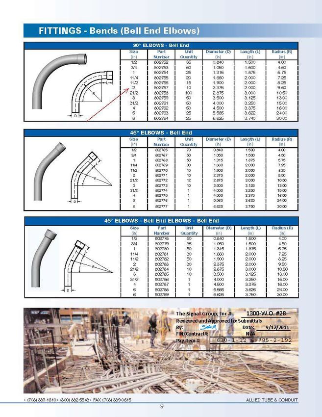
City of Port St Lucie                   Fiber Optic Network 2022
         The drop cables are to be identified on ever plan set by the EOR, but shall be no less than the following
size for Department and Connection Type:

    Utility Systems:              12F cable for Field Sites (Pump, Repump, Well Site SCADA)
                                  48F cable for Core Facilities (Admin, Water Treatment)

    Public Works:                 12F cable for CPSL tier 3-4 sites
                                  48F cable for CPSL tier 2 sites
                                  96F cable for CPSL tier 1 sites

    Traffic Engineering:          12F cable for Public Safety site connections (Police, Fire Facilities)
                                  12F cable for Traffic Signals, ITS Device Sites
                                  96F cable for designated Traffic/ITS Hub Aggregation Sites

    Parks & Rec Services:         12F cable for City Parks & Constitutional Offices
                                  48F cable for multiple Department facilities
                                  96F cable for designated City Core Ring Sites

        TIER Site Classifications: Refers to the criticality of services provided to a site.
    Tier 4: Low priority field device sites that do not affect the overall functioning of the system if offline. Site
    response required within 48 hours for any remediation required.

    Tier 3: High priority field device sites that are connected into a system that affects the functionality of
    another site in the system. Site response required within 48 hours for any required remediation.

    Tier 2: Critical Network Hub/Aggregation Facility where system applications are initiated, monitored,
    and managed and are connected to both Tier 3 & 4 for systems operations and Tier 1 sites for network
    operations. Sites are 24x7x365 operational requiring response within 8 hours and remain engaged
    until restored.

    Tier 1: Critical Network Data Center where Intra & Inter Networking is created, connected, routed and
    data is stored and exchanged between other servers and applications and broadband internet
    providers is made. Sites are 24x7x365 operational requiring response within 4 hours and remain
    engaged until restored. These sites are those with redundant entrance facilities and backup power
    from external generators.

     5     Fiber Optic Specifications                                               V1 2022
City of Port St Lucie Fiber Optic Network 2022
1.0 FIBER OPTIC CABLE SYSTEM for OUTSIDE PLANT CITYWIDE DISTRIBUTED NETWORK
1.1 FIBER OPTIC CABLE
Furnish fiber optic cable that shall be 100% compatible with the City of PSL QPL & existing fiber
optic cable plant.
1.1.1 MANUFACTURER:
The cable manufacturer shall be ISO9001 certified and shall be TL9000 registered.
1.1.2 CABLE CONSTRUCTON:
The cable shall be free of hazardous materials in compliance with RoHS 2002/95/EC. The
cable shall be of all-dielectric (non-shielded, non-metal) construction. The cable shall be
of loose- tube construction. The cable shall be of entirely gel-free construction.
1.1.3 OUTER JACKET:
Carbon Black Medium Density Polyethylene (MDPE)
1.3mm Thickness
UV Resistant
Fungus Resistant
2.5mm White Length Markings in Feet (US)
Labeled must have labels of “Fiber Optic Cable”, Year of Mfg, Cable Count and length
marking
1.1.4 RIPCORD or FAST ACCESS RIDGE: The cable may contain a ripcord under the sheath (outer
jacket) or have FastAccess ™ Ridge for accessing cable jacket.
1.1.5 WATER BLOCKING COMPOUND:
The cable shall contain a dry water blocking material under the outer jacket.
1.1.6 STRANDING/STRUCTURE:
The cable shall contain standard 12 buffer tubes in a reverse oscillation stranding
structure.
1.1.7 STRENGTH MEMBER:
The central strength member shall consist of a dielectric central element.
1.1.8 FILLER: Filler(s) may be used in the cable core. Fillers shall be 2.5mm in diameter.
1.1.9 BUFFER TUBES:
Polypropylene
Dry Water-Blocking Material inside (Gel-Free, Foam-Free)
2.5mm Outer Diameter
EIA/TIA-598-B Color Code Compliant
Standard is 12 fibers per Buffer Tube
6 Fiber Optic Specifications V1 2022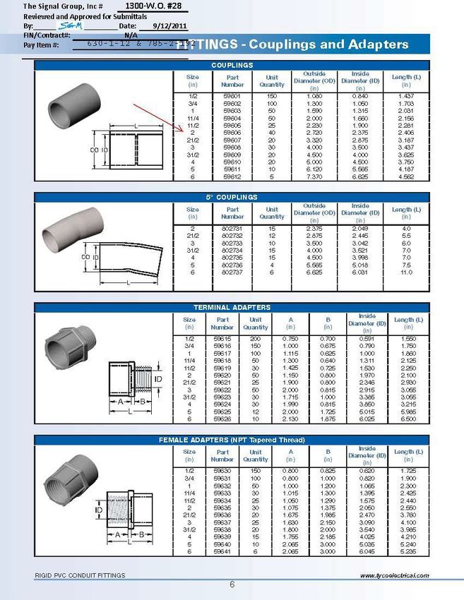
City of Port St Lucie Fiber Optic Network 2022
1.1.10 OTHER:
Fibers shall not adhere to the inside of the buffer tube. Fibers shall not stick together.
The optical fibers shall not require cleaning before placement into a splice tray.
1.1.11 OPTICAL FIBER CONSTRUCTION:
Optical fibers shall be dispersion-unshifted, step-index, single-mode fibers. Each fiber
shall consist of a Germania-doped silica core surrounded by a concentric glass cladding.
Fibers shall be a matched clad design. All fiber optic glass shall be from the same
manufacturer. Fibers shallbe coated with a dual layer acrylate protective coating. Fiber
coatings shall be colored with ultraviolet (UV) curable inks. Fibers shall be colored in
compliance with EIA/TIA-598-B.
1.1.12 OPTICAL FIBER GEOMETRY & OPTIC SPECIFICATIONS:
Core Diameter: 8.2 µm
Cladding Diameter: 125 µm +/- 0.7 µm
Core-to-Cladding Concentricity: ≤ 0.5 µm
Cladding Non-Circularity: ≤ 0.7%
Coating Diameter: 245 µm +/- 5 µm
Attenuation @ 1310 nm: ≤ 0.35 dB/km
Attenuation @ 1550 nm: ≤ 0.25 dB/km
Cutoff Wavelength: ≤ 1260 nm
1.1.13 CABLE OPERATING REQUIREMENTS:
OPERATING TEMPERATURE RANGE: -40°F to 158°F.
MINIMUM BEND RADIUS: 10 X cable outer diameter (installed), 15 X under tension
CABLE STRENGTH/MAX PULLING TENSION: 600 lbf during installation, 200 lbf installed.
CRUSHING RESISTANCE: Withstands a minimum compressive load of 125 lbf/in.
1.1.14 MANUFACTURER TESTING:
All optical fibers shall be 100% attenuation tested at the factory for compliance with
performance specifications described herein. The attenuation data for each fiber shall
be provided with each cable reel.
The cable shall be subjected to testing by the cable manufacturer in accordance with
the following ANSI/EIA/TIA-455-xx testing procedures (FOTP’s):
FOTP-3, FOTP-41, FOTP-104, FOTP-25, FOTP-33 and FOTP-8 (Result = Δ Attenuation
≤ 0.15 dB @ 1550 nm)
FOTP-37 (Result = Δ Attenuation ≤ 0.3 dB @ 1550 nm)
FOTP-82 without leakage through the open cable end.
(1 meter of cable shall withstand 1 meter static head water pressure for 1 hour)
FOTP-81 exhibiting no flow (drip or leak) of filling or flooding material @ 70° C.
FOTP-181 without loss of fiber continuity.
(Cable shall withstand a simulated lightning strike w/ 55kA peak current pulse)
7 Fiber Optic Specifications V1 2022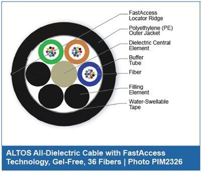
City of Port St Lucie                Fiber Optic Network 2022
    1.1.15 MISCELLANEOUS:
           The top and bottom ends of the cable shall be accessible for testing. Both ends of the
           cable shall be sealed.

            Cables included in the Corning 2021 Local Area Networks and Data Center Core Products
            Catalog will be considered when submitted for approval by specific project or work order
            application from standard outside plant interconnections.
            https://www.corning.com/catalog/coc/documents/selection-guides/LAN-1273-AEN.pdf

8     Fiber Optic Specifications                                         V1 2022
City of Port St Lucie Fiber Optic Network 2022
GENERAL PROPERTIES EXTERNAL PROPERTIES
1.3mm Medium Density Polyethylene (MDPE)
ISO 9001 Compliant Manufacturer
UV Resistant
TL 9000 Registered Manufacturer
Fungus Resistant
RoHS 2002/95/EG Compliant Materials
Black Color
All-Dielectric (Non-Shielded, Non-Metal)
2.5mm Length Markings in Feet (US)
Gel-Free, Foam-Free Construction
Labeled “City of PSL Fiber Optic Cable” every X Feet
Loose-Tube Cable
600 lbf Max Tensile Strength (Installation)
200 lbf Max Tensile Strength (Static)
125 lbf/in Crush Resistance
Operating Temperature Range of -40°F to 158°F
Minimum Bend Radius = 10 x Cable Diameter (Static)
Min. Bend Radius = 15 x Cable Diameter (Tension)
INTERNAL PROPERTIES
Water-Blocking Tape (Outside of Buffer Tubes)
Up to 12 Buffer Tubes
Reverse Oscillation Stranding Structure
2.5m Polypropylene Buffer Tubes
EIA/TIA-598 Color Code Compliant Buffer Tubes
Dry Water-Blocking Material Inside Buffer Tubes
12 Fibers per Buffer Tube
All Fibers contained in Buffer Tubes
FIBER PROPERTIES
CONSTRUCTION:
Dispersion-Unshifted Step-Index Single-Mode Fibers
Germania-Doped Silica Core surrounded by a Concentric Glass Cladding
Matched Clad Design
Dual Layer Acrylate
Coatings Ultraviolet (UV)
Curable Inks
EIA/TIA -598-B Color Code
Compliant GEOMETRY & OPTICS:
Core Diameter: 8.3µm
Cladding Diameter: 125µm +/-0.7µm
Core-to-Cladding Concentricity: ≤ 0.5µm
Cladding Non-Circularity: ≤ 0.7%
Coating Diameter: 245µm +/-5µm
Attenuation @1310nm: ≤ 0.35 dB/km
Attenuation @1550nm: ≤ 0.25 dB/km
Cut-Off Wavelength: 1260nm
9 Fiber Optic Specifications V1 2022City of Port St Lucie Fiber Optic Network 2022
1.2 FIBER OPTIC SPLICE CLOSURES
1.2.1 MANUFACTURER:
The splice closure manufacturer shall be ISO9001 certified and shall be TL9000 registered.
1.2.2 GENERAL:
Splice closures shall be “dome type” splice closures. Splice closures shall be designed for
all outdoor applications (aerial, duct, buried, etc.). Splice closures shall be free of
hazardous substances according to RoHS 2002/95/EC. Splice closures shall be
constructed of a black thermoplastic material. Splice closures shall be capable of
through, branch and mid-span type splice applications. Splice closures shall be airtight
and prevent water intrusion. Splice closures shall permit pressurization. Splice closures
shall not contain gel, or any substance which requires cleaning or removal before
splicing.
1.2.3 ENTRY MECHANISM:
Splice closures shall allow tool-less re-entry via an exterior mechanical base-to-dome
seal. The interior shall permit access to splice trays without kinking buffer tubes or
macro-bending.
1.2.4 CABLE ENTRY PORTS:
Splice closures shall have a total of 4 or 6 cable entry ports. Splice closures shall permit
the use of all ports without the use of expansion kits. Cable entry ports shall be sealed
with heat shrinkable materials.
1.2.5 DIMENSIONS:
Splice closures shall have enough interior space to accommodate 10 feet of slack
from each cable that enters the splice without exceeding the minimum bend radius of
the cable.
Splice closure shall be used as directed by the City:
SMALL CLOSURES: ≤ 22”L x 9”W x 7”D (Accommodates 6 trays/144 splices)
Through splices of 2 x ≤96 fiber trunk cables
Drop/Midspan splice sites for 1 x 12 fiber drop cable into ≥96 fiber backbone cable
LARGE CLOSURES: ≤ 28”L x 10.5”W x 10.5”D (Accommodates 8 trays/>288
splices)
Splices of 2 or more 96 to 144 fiber cables with 1 or more 12-48 fiber drop cables
Complex splices of 3 or more trunk cables
Upsizing may be required at locations depending on the City’s future plans
1.2.6 SLACK BASKET: Splice closures shall include a slack basket for managing loose buffer tubes.
10 Fiber Optic Specifications V1 2022City of Port St Lucie Fiber Optic Network 2022
1.2.7 SPLICE TRAYS:
Splice trays shall be specifically designed for use with the selected splice closure and
shall fit accordingly into the splice closure. Splice closures shall use hinged splice trays.
Splice trays shall be re-enterable. Splice trays shall provide storage and protection for
minimum of 12 splices for drop site small closures and minimum 24 splices for large
closures. Splice trays shall hold (splice sleeves) rigidly in place. Splice trays shall provide
sufficient space to prevent macro-bending of the optical fibers.
1.3 PATCH PANELS
Furnish modular interconnect centers (Patch Panels) for installation inside the equipment
cabinets.
1.3.1 MANUFACTURER:
The manufacturer shall be ISO 9001 certified and TL9000 registered.
1.3.2 PATCH PANEL CONSTRUCTION:
Patch panel housings shall be constructed of powder-painted baked-epoxy galvanized
steel. Patch panels shall be designed for cable entry parallel to the rear of the panel.
Cable openings shall be protected by grommets. The front of the panel shall form a shelf
providing physical protection of connectors and routing options for the patch cords. The
housing shall include strain relief, bend radius protection, and short-term cable
retention clamps.
1.3.3 PORTS:
Patch panels shall provide 12 LC SM coupler ports with ceramic inserts on its front-facing
panel unless restoring a legacy site with ST or SC splice on pigtail connectors.
Compatible with pre-assembled coupling plates (6 or 8 ports per plate, 3 plates per row).
Designed to contain 24 ports per unit of rack space (1U=1.75”H).
Expandable up to 144 ports (24 ports per unit of rack space, 6U total).
Dust caps included with all coupler ports.
Couplers shall be configured in an arrangement to facilitate easy access to each coupler pair.
1.4 PIGTAILS
1.4.1 MANUFACTURER:
The manufacturer shall be ISO 9001 certified compliant.
1.4.2 PIGTAIL CONSTRUCTION:
Pigtails shall consist of a standard 250µm fiber single-mode fiber enveloped with a
900µm tight buffer. The fiber shall be constructed with a Dual-Acrylate Slip Layer
between the 250µm fiber and 900µm tight buffer. Stripping the 900µm tight buffer off
the 250µm fiber shall only require the use of standard mechanical strippers and shall
not require the use of thermal strippers.
11 Fiber Optic Specifications V1 2022City of Port St Lucie Fiber Optic Network 2022
The fiber type shall be single mode and the core characteristics shall be splice
compatible with existing fiber, matching the specifications stated in Section 1.1.12
unless campus project specifically calls for multi-mode cable.
Pigtails shall be LC, 12 or 24-fiber capacities Pigtails shall be protected with dust caps on the
connector ferrules until connected to a port.
1.4.3 SPECIFICATIONS:
Pigtails and their pre-assembled connectors shall also meet or exceed the following
specifications:
CONNECTOR:
Connector Type: LC (Non-Keyed/No Security)
Polish/Contact Type: UPC (Ultra Polish/Physical Contact)
Boot: Blue, Fungus Resistant material
Body: Composite
Ferrule: 2.5mm Zirconia Ceramic
Max. Typical Loss 0.15dB
Reflectance/Back Reflection: ≤ -58dB
Operating Temperature: -40°F to 185°F
Intermateability Standard: TIA/EIA-604-2
Durability Testing: ≤ 0.2 dB loss/1000 re-matings, FOTP-21
CABLE:
Type: Simplex (1F) or 12F, Single-Mode
Jacket: 0.9mm, color coded OFNR rated
Length: 2 meters
Minimum Bend Radius: 30mm
GENERAL:
Material Compliance: ITU-T G.652.D and ITU-T G.657.A1
Substance Restrictions: RoHS Compliant construction
1.5 PIGTAIL MODULE
1.5.1 MANUFACTURER:
The manufacturer shall be ISO 9001 certified compliant.
1.5.2 PIGTAIL MODULE CONSTRUCTION:
Pigtail Modules are allowed for use when terminating backbone cables. Pigtail Modules
shall be LC, 12 or 24-fiber capacities. For use in Corning CCH housings.
Each module provides strain-relief for the pigtail and offers the advantage of greater
protection to the cables and connectors being installed when the pigtails will be routed and
spliced in a separate housing. Available with both ribbon and 900 μm tight-buffer MIC®
Cable types, each CCH pigtail module is factory terminated and tested.
12 Fiber Optic Specifications V1 2022City of Port St Lucie Fiber Optic Network 2022
The fiber type shall be single mode and the core characteristics shall be splice
compatible with existing fiber, matching the specifications stated in Section 1.1.12.
Pigtails shall be protected with dust caps on the connector ferrules until connected to a port.
The optical specification of the hardware is a typical module insertion loss, typical 0.15 dB and
maximum of 0.40 dB.
1.6 PIGTAIL SPLICE CASSETTE
1.6.1 MANUFACTURER:
The manufacturer shall be ISO 9001 certified compliant.
1.6.2 PIGTAIL SPLICE CASSETTE CONSTRUCTION:
Pigtail Splice Cassette are allowed for use when terminating backbone cables. Pigtail Splice
Cassettes shall be LC, 12 or 24-fiber capacities.
Each cassette provides strain-relief for the pigtail and offers the advantage of greater
protection to the cables and connectors being installed when the pigtails will be routed and
spliced in a separate housing. Available with both ribbon and 900 μm tight-buffer MIC®
Cable types, each CCH pigtail module is factory terminated and tested.
The fiber type shall be single mode and the core characteristics shall be splice
compatible with existing fiber, matching the specifications stated in Section 1.1.12.
Pigtails shall be protected with dust caps on the connector ferrules until connected to a port.
The optical specification of the hardware is a typical module insertion loss, typical 0.15 dB and
maximum of 0.40 dB.
For use in Corning CCH housings.
1.7 PATCH CORDS/CABLES
1.7.1 MANUFACTURER:
The manufacturer shall be ISO 9001 certified.
1.7.2 PATCH CORD CONSTUCTION:
Patch cordage shall be factory pre-assembled, pre-terminated patch cords that are
compatible with the existing fiber system, adhering to the fiber specifications found in
Section 1.1.12. All inside plant (IP) assemblies shall meet NEC jacketing requirements
for the application.
Jumpers shall be of the same fiber core size, performance and connector type as the
existingcable system (see Section 1.1 “Fiber Optic Cable”).
Patch cords shall be protected with dust caps on the connector ferrules.
13 Fiber Optic Specifications V1 2022City of Port St Lucie Fiber Optic Network 2022
1.7.3 SPECIFICATIONS:
Patch cords and their connectors shall also meet or exceed all of the following specifications:
CONNECTOR:
Connector Type: LC (preferred by the City), ST, SC (Legacy)
Polish/Contact Type: UPC (Ultra Polish / Physical Contact)
Connector Body: Composite, Blue (Typical)
Connector Boot: White (Typical)
Connector Ferrule: 2.5mm Zirconia Ceramic
Max. Typical Loss: ≤ 0.15dB (UPC)
Reflectance/Back Reflection: ≤ -59dB (UPC)
Operating Temperature: -40°F to 185°F
Intermateability Standard: TIA/EIA-604-2
Durability Testing: ≤ 0.2 dB loss per 1000 re-matings, FOTP-21
CABLE:
Type: Duplex, Single-Mode
Jacket: 3mm, Yellow, OFNR rated
Length: Varies 1 to 3 meters
Minimum Bend Radius: 30mm
Crush Resistance: 1000 N/10cm
Tensile Strength: 200 N
GENERAL:
Materials/Construction: LSZH, FRNC
Substance Restrictions: RoHS Compliant construction
1.8 SPLICING EQUIPMENT
1.8.1 MANUFACTURER:
The fusion splicer manufacturer shall be ISO9001 certified and TL9000 registered.
1.8.2 FUSION SPLICER FEATURES:
The fusion splicer shall be designed to splice standard single-mode fibers with a
cladding diameter of 125µm and coating diameters from 250 µm to 900 µm. The fusion
splicer shall be equipped with a heat shrink oven compatible with 60mm splice sleeves.
The fusion splicer shall be equipped with a light injection detection (LID) splice loss
measurement system (not only a splice loss estimation system). The fusion splicer shall
be equipped with a monitor display that allows inspection of the fiber ends with 120 X
magnification.
14 Fiber Optic Specifications V1 2022City of Port St Lucie Fiber Optic Network 2022
1.8.3 SPECIFICATIONS:
The fusion splice shall also meet or exceed all of the following specifications:
Typical Splice Loss (Standard Single-Mode): < 0.05 dB (similar fibers)
Splice loss measurement accuracy: +/- 0.02 dB
Operating Temperature Range: -15° to +50°C
Relative Humidity:City of Port St Lucie Fiber Optic Network 2022
1.10 INSTALLATION
1.10.1 PRECONSTRUCTION:
Before starting any installation, the City shall be notified 3 business days in advance. Failure
to notify the City may result in rejection of the installation and may subject the contractor
to be responsible for removal of the installation at no cost to City of PSL. Before installation,
the cable to be installed shall be reel tested (Section 1.11.12).
1.10.2 PERSONNEL:
Personnel performing the cable installation shall be adequately trained and shall be IMSA
MOT Level 1 certified. All Contractor personnel (including subcontractors) shall be
thoroughly familiar with and shall comply with all Occupational Safety and Hazard Act
(OSHA) regulations.
1.10.3 MAINTENANCE of TRAFFIC (MOT) PLAN:
An approved MOT Plan shall be required any time work is being performed within the City
of PSL Right of Way, regardless of permit requirements. MOT Plans shall conform to the
latest FDOT Design Standards 600 Series and the latest Manual on Uniform Traffic Control
Devices (MUTCD). The Contractor shall be responsible for setup and removal of all MOT
devices.
1.10.4 COMPLIANCE:
The Contractor shall obtain a Road Closure Permit from the City of PSL or FDOT, where
necessary. Cable shall be installed in compliance with NEC requirements where
applicable. The Contractor shall receive an Excavation Permit from the City of PSL, where
necessary.
1.10.5 INSTALLATION:
Conventional fiber optic cable installation techniques shall be used within the conduit
in such a manner that the optical and mechanical characteristics of the cables are not
degraded in any manner at the time of installation. Use of Air Blown Fiber System cable
and/or Air Blown Fiber System installation techniques (such as HASB and the piston
method) shall not be permitted. Cables shall not be pushed into conduits. (Pushing can
violate the bend radius)
1.10.6 UNREELING:
Cable shall be rolled off of the spool. Spinning off the side of the spool end shall not be
permitted. (It will put a twist in the cable for every turn on the spool.) The figure-eight
configuration shall be used for storing cable at intermediate locations to prevent kinking
or twisting when the cable must be unreeled and backfed. Pulling and reel locations
should be set near the sharpest conduit bend locations (i.e. corner vaults, etc.) where
possible.
16 Fiber Optic Specifications V1 2022City of Port St Lucie Fiber Optic Network 2022
1.10.7 PULLING:
Fiber optic cable shall be installed by hand or by using a mechanical pulling machine.
When a mechanical/automated pulling machine is used it shall be equipped with a
monitored tension meter/tension control. Cable pulling tension shall be continuously
monitored; the pulling process shall not be allowed to exceed the maximum tension
specified by the manufacturer of the cable. A proper wire mesh pulling grip and swivel
shall be used in the cable pulling process. Fuse links and breaks shall be used to insure
that the cable will not be subjected to stresses exceeding 600 lbf.
The minimum-bending radius of the cable shall not be exceeded. Corner rollers
(wheels), if used, shall not have radii less than the minimum installation bend radius of
the cable. A series array of smaller wheels may be used for accomplishing the bend if
the cable manufacturer specifically approves the array. Entry guide chutes shall be used
to guide the cable into the pull- box conduit ports. When simultaneously pulling fiber
optic cable with other cables, separate grooved rollers shall be used for each cable.
On runs over 100 feet, lubricating compound shall be used to minimize cable-to-conduit
friction. Lubricating compound shall be a water-based compound specifically produced
for fiberoptic cable lubrication. Lubricants such as dish soap and other substitutes shall
not be permitted.
Every effort shall be made to pull cables from a conduit in as straight an angle as
possible. “Offset” pulling shall be avoided whenever possible. (Pulling on an angle can
cause damage to the cable.) The number of 90° turns on a pull shall not exceed 4 within
750lf segment.
The cable shall be installed in continuous lengths from splice point to splice point, as
indicated in the plans.
1.10.8 CABLE SLACK REQUIREMENTS:
Throughout the cable plant, pull and store excess cable slack at each pull box, splice box,
hub, and each TMC or TOC. The following lengths of slack cable are minimums:
Fiber Pull Box (17”x30”): 50 ft.
Fiber Splice Box (24”x36” or 30” x48”): 220 ft.
(100’ each side of any splice closure and allotting 20lf for inside the splice closure)
Bridge Barrier Wall: 5 ft.
(Contractor must maintain the minimum bend radius inside bridge box)
Device Cabinet: 20 ft.
Hub Building (Inside): 100 ft.
Cable slack shall be neatly arranged and looped horizontally on the floor of each pull
box. Coils of slack from separate cables shall be grouped together and taped individually.
17 Fiber Optic Specifications V1 2022City of Port St Lucie Fiber Optic Network 2022
Do not leave slack cable lying free (uncoiled) on the ground, bottom of a pull box, or
floor of a Device Cabinet, Hub Building, etc., except during the installation/pulling
process.
When coiling and storing cable slack the cable minimum bend radius shall not be
exceeded. The cable slack/coils shall not protrude above the pull box/splice vault cover
or in any way interferewith the placing or replacing the splice box cover.
1.10.9 LABELING & DOCUMENTATION:
Document the sequential cable length markings at each pull box and splice vault wall
that the cable passes through and include this information with the as-built
documentation.
Each cable that enters/exits a conduit inside a pull box shall be clearly labeled with a
weatherproof colored tape within 3 foot of exiting the conduit. The color of the “tape”
placed on each cable shall identify which direction the cable is “headed” from this
pullbox. The color standard to be utilized is:
Yellow – East
Green – West
Blue – North
Red - South
Each cable that enters/exists inside a pullbox shall have a tag/label attached to indicate:
the cable type, fiber count, direction, and date. The tag shall provide enough space for
all info to be written clearly and legibly on its front in permanent marker.
1.10.10 INSPECTION:
Prior to splicing and/or termination, the City shall be notified immediately when cable
installation (pulling) is complete so that they may be present during inspection of the
cable installation. The cable shall be inspected at all accessible locations (pull boxes,
splice vaults, traffic cabinets, etc.) for correctness and for damage to the cable that may
have occurred or may have been preexisting.
Once the cable installation has been inspected and met by approval from the City, then
the contractor may proceed with completion of the installation (splicing, termination,
testing, etc.).
1.10.11 DAMAGE:
The City shall be notified immediately of any damage to the cable, including, but not
limited to: any nick that penetrates the outer jacket of the cable (even if buffer tubes,
gel, fibers, etc., are not exposed); any breaks, kinks, twists, warps, bends, or crushing of
the cable that result in a deformation that does not restore to normal on its own, even
if the damage appears to be only superficial.
18 Fiber Optic Specifications V1 2022City of Port St Lucie Fiber Optic Network 2022
If any damage to the fiber optic cable occurs before, during or after installation, the
contractor shall not attempt to repair the damage before the City has been notified and
exercised its option to inspect the damage prior to any splicing or termination activity.
The Contractor may present a repair plan, consistent with above specified restoration
periods, inclusive of the procedure to be implemented, the beginning or end point of
any such repair, the location of any additional proposed splice points.
Once inspected, the City will choose the repair method and direct all repair operations,
including but not limited to placing a new fiber segment from two (2) existing original
reel end splice points, sealing the cable, required emergency temporary or permanent
splicing -or re-splicing of damaged cable at approved vaults, etc.
The City reserves the right to perform any repairs itself wherever to maintain critical
operations and/or it deems necessary and seek compensation for damage restoration
from any party damaging the City’s Fiber Optic Network Infrastructure (cable, conduit
or pull boxes).
When making repairs to damaged cable segments, the existing damaged fiber optic
cable must be removed from the restored pathways so no damaged or un useable fiber
optic cable is left in any City conduit.
Any Contractor, Owner or Third Party who damages the City of Port St. Lucie fiber optic
infrastructure, including conduits, fiber optic cables, tracer wires, handholes and locate
system assets, without having previously sought locates from 811 Sunshine One Call, or
who damages the infrastructure that is clearly marked within eighteen (18”) inches of a
locate flag or mark, shall bear the full financial responsibility for the remediation costs
including any emergency or temporary repair activity which may include duct repairs,
cable replacement, splicing and termination; and, permanent cable segment
replacement with associated cabling, splicing, terminations and testing.
1.11 FIBER OPTIC SPLICING REQUIREMENTS
All fibers in the fiber optic cable shall be spliced and/or terminated.
1.11.1 SPLICE PLAN:
CPSL is to provide a fiber allocation and/or splice plan showing the location and splices to be
performed at any location to ensure maintaining proper allocation within Departments
and/or Networks.
Contractor may be asked to provide splice schematic for large fiber cross splice sites or sites
where >3 cables are splices between cables, buffers and fibers as a plan to follow for field
personnel.
19 Fiber Optic Specifications V1 2022City of Port St Lucie Fiber Optic Network 2022
All splicing shall be performed according to the plan. Document each splice location and
identify the source and destination of each fiber in each splice tray. Document all fiber
colors and buffer jacket colors used during installation. Develop and document a sequential
fiber numbering plan as required in the TIA/EIA-598-A standard.
Contractor to asbuild every splice closure and termination housing to ensure compliance
with optical allocation, routing and assignment.
1.11.2 FUSION SPLICING:
The fusion technique shall be used for all splices and terminations. A fusion splicing
machine (Fusion Splicer) shall be used to splice all optical fiber as specified in Section
1.6.
1.11.3 PERSONNEL:
All splicing personnel shall be adequately trained for the fusion splicing, and shall
possess a fiber optic splicing certification from an industry recognized authority such as
Corning, FIS, Light Brigade, ETA or other recognized industry resource.
1.11.4 SPLICING EQUIPMENT PREPARATION:
Provide splice closures, organizers and incidentals, and cable end preparation tools and
procedures, compatible with the cable type being delivered. Fusion splicing equipment
shall be cleaned and calibrated per the manufacturer’s specifications, and specifically
adjusted to the fiber and environmental conditions at the start of each splicing shift.
1.11.5 SPLICE CLOSURE PREPARATION:
Select a splice closure appropriate for the application that complies with section (1.2
Splice Enclosures) and shall allow all of the fibers in each cable to be spliced and stored.
All cables shall enter into the splice closure on only one side (“butt” configuration). Only
one cable per entry port shall be allowed (except for mid-span “oval” ports). A minimum
of 10 feet of cable from each cable entering the closure (i.e. 20 feet of trunk cable in
mid-span splicing) shall be prepared and installed within the enclosure.
1.11.6 SPLICE TRAY PREPARATION:
Splice trays shall be selected that will accommodate the required number of splices and
provide sufficient storage space and protection to prevent micro-bending of slack fiber.
Accomplish loose tube entry using a mid-access tool or split-entry tool. Only open the
buffer(s) that contain(s) the fibers to be spliced, and only cut the fibers that must be
spliced. Buffer tubes shall be secured onto the splice tray and held rigidly in place. At
least 24” of loose fiber shall be exposed for splicing and the remainder shall be stored
as slack, along with any exposed fibers that will not be spliced.
20 Fiber Optic Specifications V1 2022City of Port St Lucie Fiber Optic Network 2022
1.11.7 SPLICING:
Perform fusion splicing according to latest version of the cable manufacturer’s and
fusion splicer’s procedures, accepted standards, codes, and practices; or as directed by
the City. Fibers shall not be fused or re-fused more than a total of 3 times.
1.11.8 SPLICE LOSS:
Individual splice loss shall not exceed 0.05 dB loss as measured by the fusion splicer and
0.15dB on a bi-directional average of an OTDR.
1.11.9 SPLICE PROTECTION:
Each spliced fiber shall be packaged in a 60mm heat shrinkable splice protection sleeve
with strength member. The protection sleeve shall cover the splice and any bare fiber
stripped of its coating.
1.11.10 STORAGE:
A maintenance loop at each Pull Box or Fiber Splice Box shall be per Section 1.10.
1.11.11 LABELING:
Each cable entering a splice closure shall be clearly labeled with a weatherproof
tape/tag within 1 foot of the splice closure, which shall indicate: the cable type, fiber
count, length marking, “from” direction, and the cable’s origination and termination
points. Splice closures shall be tagged with a weatherproof tag/label.
The tag shall provide enough space for all info to bewritten clearly and legibly on its front.
Labeling shall include: date of installation, splicing technician initials, splice
diagram/chart reference #, etc. A splice diagram/chart shall be included inside the
splice. The diagram will define each fiber from every cable that enters the enclosure.
1.12 FIBER OPTIC TERMINATION REQUIREMENTS
All fiber optic cables shall be terminated by means of fusion splicing onto factory pre-
terminated assemblies (pigtails) with LC connectors. Patch Panels, Pigtails and Splice Trays
shall be provided as specified earlier in this document. Patch panels shall accommodate all
fibers entering equipment cabinets. Splice Trays shall be selected that fit the patch panel.
1.12.1 PATCH PANEL PREPARATION:
The cable shall be clamped to the patch panel by means of a “hose clamp”. The cable
central strength member shall be secured (clamped) to the patch panel. Protective spiral
wrap shall be placed and secured (taped) over the cable and buffer tubes where the
cable enters the panel and passes through the grommet. 10 feet of cable entering the
panel shall be prepared and installed within the enclosure.
Pigtails shall be spliced onto the bare fibers as detailed in section 1.9. The splicing
sequence shall follow the order of the fiber # position within the buffer and cable.
21 Fiber Optic Specifications V1 2022City of Port St Lucie Fiber Optic Network 2022
Once all bare fibers have been terminated onto pigtails, the pigtails shall be connected
to the LC or SC coupler ports according to their position within the fiber or cable. Pigtails
shall be arranged neatly within the panel without crushing, exceeding the minimum
bend radius, or introducing losses. Dust caps shall be placed on all unused coupler ports.
All fiber terminations shall be visually inspected, and optically tested for attenuation
and reflectance, and shall exhibit an optical performance with a maximum insertion loss
and a minimum return loss as noted on the qualified product cut sheet.
1.12.2 LABELING:
PATCH PANELS:
Patch panels shall be labeled to indicate which cable and direction they provide access
to. Port plates shall be labeled to indicate which buffer within the cable they provide
access to. Coupler ports shall be labeled to identify which fiber # or color that the port
provides access to.
EQUIPMENT PATCH CORDS:
Patch cords that provide connections to network switches shall be labeled at each end
to indicate the source cable & fiber #/color it connects to for transmit and receive, and
which porton the switch it connects to.
JUMPER PATCH CORDS:
Jumper patch cords, if any, shall be labeled at each end to indicate which cable & fiber
#/colors that they are connected to for transmit and receive and shall include labeling
which indicates the “To” and “From” connection end points.
1.13 ACCEPTANCE TESTING
The Fiber Optic Cable Network shall be tested as follows:
1.13.1 MANUFACTURER’S TEST AND CERTIFICATION:
Each reel of fiber optic cable shall be accompanied by the manufacturer's test data
(Section 1.1.14). The manufacturer’s test data shall identify each fiber in each cable and
list its factory- tested attenuation in dB/km. Attenuation shall meet attenuation
requirements Section 1.1.12.
1.13.2 PRE-INSTALLATION TESTS (REEL TEST):
The Contractor is to reel test the fiber optic cable prior to its installation. Each optical
fiber in the cable shall be tested from one end at one wavelength with a compatible
OTDR. Test for continuity, length, anomalies, and approximate attenuation. Record
each measurement with color, location and fiber type measured, and submit the
documentation to the City in electronic format. If the tested loss per Km exceeds the
loss from the manufacturer's test data the City will reject the cable.
22 Fiber Optic Specifications V1 2022City of Port St Lucie Fiber Optic Network 2022
1.13.3 POST INSTALLATION TESTS (FINAL TEST):
1. Contractor to attempt to notify the City 3 business days via email or test in advance of
the Final Testing so that the City may elect to be present for the testing.
2. After installation (splicing and termination) is complete, the optical fibers shall be tested
for loss characteristics. A full bi-directional test (using bi-directional averaging) shall be
performed on all terminated fibers in each cable using an Optical Time Domain
Reflectometer (OTDR) (See Section 1.9).
3. Any fibers in a “building or device cabinet or other horizontal drop cable” that remain
un-terminated or un-spliced at one end on the project and therefore are "left bare at
one end" shall be protected for future use at the "bare end" and shall be tested from
the terminated end in a uni-directional OTDR test to prove termination attenuation and
fiber continuity.
4. All Singlemode Fibers shall be tested at 1310nm and 1550nm. All Multimode fibers shall
be tested at 850nm and 1300nm. There may be instances where Contractor(s) are
required to test additional wavelengths for CPSL course or dense wave division
multiplexed deployment projects which will be shown in plans for project by the EOR.
5. If the OTDR does not have internal fiber to eliminate any dead zone effects on the test,
the Contractor shall use a factory assembled patch cord, or launch cables equal to a
length of 150% of the Dead Zone as published by the OTDR Manufacturer. The launch
cable shall have the appropriate connectors to allow for connection to the terminated
fiber port without the use of additional couplers.
6. Test result printouts shall include, but not be limited to, the following:
a. Cable ID and Fiber ID;
b. Distance of trace;
c. Total Loss;
d. Splice Loss;
e. Beginning Testing Location;
f. End of Fiber Testing Location;
g. Operator/Technician Name or Initials;
h. Date and Time test was performed;
i. Test Wavelength;
j. Test Pulse Width;
k. Refractory Index
7. All installation test data shall be submitted in electronic format both PDF summary
reports as well as native OTDR trace files (.trc file format unidirectional traces & .bdr
file format for bidirectional traces) to the City as basis for acceptance. The Contractor
23 Fiber Optic Specifications V1 2022City of Port St Lucie Fiber Optic Network 2022
shall provide to the City of PSL Department at no charge a “viewer” license of any
OTDR software.
1.14 TRAFFIC & UTILITIES OSP MULTI-PAIR CABLES (COPPER DATA CABLES):
For department specific device connections, the Contractor shall supply manufacturer
specified multi-conductor composite cables to support SCADA, serial or ethernet
communications and/or power for such devices.
For ethernet connected devices, the Contractor shall furnish and install multi-pair data cable
(CAT6) that will support full-duplex Fast Ethernet operations up to 10GB operations. Furnish
all tools, materials, connectors, and required consumables, and perform all installation
operations necessary to provide a complete, fully operational multi-pair data cable (CAT6).
For all City of PSL ISP applications refer to specifications on the city website at:
https://www.cityofpsl.com/Home/ShowDocument?id=8075
1.14.1 MANUFACTURER:
The manufacturer shall be ISO9001 certified and TL9000 registered.
1.14.2 SPECIFICATIONS:
Multi-pair data cable, CAT6 shall meet the minimum specifications as published on city
website in table 27 10 11.01.B.
1.14.3 CONNECTORS:
CAT6 cabling shall be terminated with Connectors shall be RJ-45 (8P8C) type connectors and
110 style IDC pair terminations.
1.14.4 TESTING:
Category 6A performance testing shall be done according to the requirements of
ANSI/TIA-568.2-D-2018 and ANSI/TIA-1152-A-2016.
24 Fiber Optic Specifications V1 2022City of Port St Lucie Fiber Optic Network 2022
2 NETWORK DEVICES
Provide hardened, Managed Field Ethernet Switches (MFES) for drop termination connections
supporting field devices for Traffic Engineering, Utility Systems, Parks and Recreation, Public
Works, and Information Technologies. The MFES shall be 100% compatible and interoperable with
the existing Ethernet networks.
The Contractor shall follow project plans for determining the number of POE+ connected devices
and shall size the power supply to support the required power draw over POE ports.
2.1 MANUFACTURER:
The manufacturer shall be ISO9001 compliant.
2.2 CONSTRUCTION:
All parts shall be made of corrosion resistant materials such as plastic, stainless steel,
anodized aluminum, brass, or gold-plated metals. Every conductive contact surface shall be
gold-plated or made of a noncorrosive, non-rusting, conductive metal. The MFESs shall be
constructed with no moving parts (Fan-Less Design).
2.3 PHYSICAL/MECHANICAL:
Height: ≤ 8”H x ≤ 8”W x ≤ 5.5”D
Mounting: DIN rail mounted
2.4 ELECTRICAL:
All wiring shall meet NEC requirements and standards.
Power Consumption: ≤ 42W
Input Voltage: 9.6-60 VDC; 110/220 VAC
2.5 ENVIRONMENTAL:
Operating Temperature Range: -40°C to +75°C
Humidity: ≤ 95 % non-condensing
Ingress protection: IP40 rated (1mm objects)
Compliance: NEMA TS 2 Standard (Traffic Control Equipment)
2.6 ETHERNET PORTS:
The Contractor is to review the project plans in order to determine the required number of ports.
“Fast Ethernet” (10/100BaseTX) Copper Ports.
Copper ports shall be RJ-45 Type.
Auto-negotiate speed (10/100/1000) and duplex (half/full).
IEEE 802.3 standard compliant pinouts.
Fiber Optic single-mode “Gigabit Ethernet” (1000BaseX) ports
Each optical port shall consist of a pair of SC or LC Type connectors only
Optical power budget ≥ 15 dB
25 Fiber Optic Specifications V1 2022City of Port St Lucie Fiber Optic Network 2022
2.7 WARRANTY: 5 years manufacturer warranty from the date of purchase.
2.8 PERFORMANCE:
Switching Bandwidth: ≥ 20 Gbps non-blocking
VLANS: 1,000
IGMP Groups: 1,000
Minimum 32KB MAC address table (16,000 MAC addresses)
Minimum Mean Time Before Failures (MTBF) of 10 years (≥519,190 hours)
2.9 OTHER:
Diagnostic Light Emitting Diodes (LEDs) indicating Link, TX, RX and speed for each port, as
well as Alarms and Power on unit. LED indicators shall be on the front panel of the unit.
2.10 MANAGEMENT CAPABILITIES:
The City shall be able to manage each MFES individually or as a group/cluster for switch
configuration, performance monitoring, and troubleshooting. The MFES shall support
setup/configuration and management and/or monitoring of all user programmable features
and functions via the following:
Fast Boot Express setup
Web Device Manager, Industrial Network Director (IND)
MIB, Smartport, SNMP, Syslog, storm control, unicast, multicast, broadcast
SPAN sessions, RSPAN
DHCP server, customized DOM (digital optical management)
Embedded Event Manager (EEM), Plug-n-Play Agent
2.11 CYBER SECURITY FEATURES:
The MFES shall support the following standard and advanced cyber security features:
SCP, SSH, SNMPv3, TACACS+
RADIUS Server/Client
MAC Address Notification, BPDU Guard
Port-Security, Private VLAN
DHCP Snooping, Dynamic ARP Inspection, IP Source Guard
802.1x, Guest VLAN, MAC, Authentication Bypass
802.1x Multi-Domain Authentication, Storm Control, Trust Boundary
FIPS 140-2, Netflow Lite
2.12 NETWORKING FEATURES:
Standard and advanced (layer 2+) networking features shall include, but are not limited to:
Layer 2 IPv6 - IPv6 Host support, HTTP over IPv6, SNMP over IPv6
Layer 3 Routing -
Internet Group Messaging Protocol (IGMP) IGMPv1, v2, v3 Snooping, IGMP filtering, IGMP
Querier
Quality of Service (QoS) priority classify by port, Ingress Policing, Rate-Limit, Egress
Queueing/shaping, AutoQoS, QoS
26 Fiber Optic Specifications V1 2022City of Port St Lucie Fiber Optic Network 2022
2.13 NETWORKING STANDARDS / IEEE COMPLIANCE:
The MFES shall comply with all applicable IEEE networking standards for Ethernet
communications, including but not limited to:
IEEE 802.1D MAC Bridges, STP IEEE 802.3at Power over Ethernet
IEEE 802.1p Layer2 COS provides up to 25.5W DC power to each
prioritization end device
IEEE 802.1q VLAN IEEE 802.3af Power over Ethernet
IEEE 802.1s Multiple Spanning- IEEE 802.3at Power over Ethernet Plus
Trees IEEE 802.3ah 100BASE-X SMF/MMF only
IEEE 802.1w Rapid Spanning- IEEE 802.3x full duplex on 10BASE-T
Tree IEEE 802.3 10BASE-T specification
IEEE 802.1x Port Access IEEE 802.3u 100BASE-TX specification
Authentication
IEEE 802.3ab 1000BASE-T specification
IEEE 802.1AB LLDP
IEEE 802.3z 1000BASE-X specification
IEEE 802.3ad Link Aggregation
(LACP) IEEE 1588v2 PTP Precision Time Protocol
IEEE 802.3af Power over IEEE 802.1AS PTP
Ethernet provides up to 15.4W IEEE 802.1Qbv TSN
DC power to each end device
2.14 IETF RFC COMLIANCE:
RFC 768: UDP RFC 1256: ICMP Router Discovery
RFC 783: TFTP RFC 1305: NTP
RFC 791: IPv4 protocol RFC 1492: TACACS+
RFC 792: ICMP RFC 1493: Bridge MIB Objects
RFC 793: TCP RFC 1534: DHCP and BOOTP
RFC 826: ARP interoperation
RFC 854: Telnet RFC 1542: Bootstrap Protocol
RFC 951: BOOTP RFC 1643: Ethernet Interface MIB
RFC 959: FTP RFC 1757: RMON
RFC 1157: SNMPv1 RFC 2068: HTTP
RFC 1901,1902-1907 RFC 2131, 2132: DHCP
SNMPv2 RFC 2236: IGMP v2
RFC 2273-2275: RFC 3376: IGMP v3
SNMPv3 RFC 2474: DiffServ Precedence
RFC 2571: SNMP RFC 3046: DHCP Relay Agent Information
Mgmt Option
RFC 1166: IP RFC 3580: 802.1x RADIUS
Addresses RFC 4250-4252 SSH Protocol
27 Fiber Optic Specifications V1 2022You can also read