CE850 ELLIPTICAL TRAINER OWNER'S MANUAL
←
→
Page content transcription
If your browser does not render page correctly, please read the page content below
CE850 ELLIPTICAL TRAINER
OWNER’S MANUAL


TABLE OF CONTENTS
4       IMPORTANT SAFETY INSTRUCTIONS
4       IMPORTANT ELECTRICAL INSTRUCTIONS
7       IMPORTANT OPERATION INSTRUCTIONS
7       PRODUCT REGISTRATION
8       CE850 ASSEMBLY INSTRUCTIONS
16      CONSOLE OPERATION
20      PROGRAMMABLE FEATURES
31      USING HEART RATE TRANSMITTER
33      ENGINEERING MODE
34      GENERAL MAINTENANCE
35      MANUFACTURER’S LIMITED WARRANTY

Thank you for purchasing our product, please save these instructions. Please do not perform or attempt any
customizing, adjustments, repair or maintenance that is not described in this manual.

                                                                                                             3
Congratulations on your new elliptical trainer and welcome to the Spirit Fitness family!
Thank you for your purchase of this quality elliptical trainer from Spirit Fitness. Your new elliptical trainer was manufactured by
one of the leading fitness manufacturers in the world and is backed by one of the most comprehensive warranties available.
Through your dealer, Spirit Fitness will do all we can to make your ownership experience as pleasant as possible for many
years to come. If not purchased direct from Spirit Fitness, the local dealership where you purchased this elliptical trainer is
your administrator for all Spirit Fitness warranty and service needs. Their responsibility is to provide you with the technical
knowledge and service personnel to make your experience more informed and any difficulties easier to remedy.
Please take a moment at this time to record the name of the dealer, their telephone number, and the date of purchase below
to make any future, needed contact easy. We appreciate your support and we will always remember that you are the reason
that we are in business.
Yours in Health,
Spirit Fitness
NAME OF DEALER______________________________________
DEALER PHONE #______________________________________
PURCHASE DATE______________________________________
4Important Safety Instructions • Never drop or insert any object into any openings.
• Do not use outdoors.
WARNING • To disconnect, turn all controls to the off position, then
When using an electrical appliance, basic precautions should remove the plug from the outlet.
always be followed, including the following: • Do not attempt to use your elliptical for any purpose
Read all instructions before using this appliance. other than for the purpose it is intended.
DANGER - To reduce the risk of electric shock: • The hand pulse sensors are not medical devices.
Always unplug this appliance from the electrical outlet Their purpose is to provide you with an approximate
immediately after using and before cleaning. measurement in relation to your target heart rate. Use
WARNING - To reduce the risk of burns, fire, electric shock, or injury of a chest transmitter strap (sold separately) is a much
to persons, install the elliptical on a flat level surface with access to a 110- more accurate method of heart rate analysis. Various
volt, 5-amp grounded outlet with only the elliptical plugged into the circuit. factors, including the user’s movement, may affect the
accuracy of heart rate readings. The pulse sensors are
DO NOT USE AN EXTENSION CORD UNLESS IT IS A 14AWG OR
BETTER, WITH ONLY ONE OUTLET ON THE END:
intended only as exercise aids in determining heart rate
trends in general.
• Do not operate elliptical on deeply padded, plush or
shag carpet. Damage to both carpet and elliptical • Wear proper shoes. High heels, dress shoes, sandals
may result. or bare feet are not suitable for use on your elliptical.
Quality athletic shoes are recommended to avoid
• Keep children away from the elliptical. There are leg fatigue.
obvious pinch points and other caution areas that can
cause harm. • This appliance is not intended for use by persons with
reduced physical, sensory or metal capabilities, or lack
• Keep hands away from all moving parts. of experience and knowledge, unless they have been
• Never operate the elliptical if it has a damaged cord given supervision or instruction concerning use of the
or plug. If the elliptical is not working properly, call your appliance by a person responsible for their safety.
dealer. • Keep children under the age of 13 away from this
• Keep the cord away from heated surfaces. machine.
• Do not operate where aerosol spray products are SAVE THESE INSTRUCTIONS - THINK SAFETY!
being used or where oxygen is being administered.
Sparks from the motor may ignite a highly gaseous
environment. 5Important Electrical Instructions resistance for electric current, reducing the risk of electric shock.
This product is equipped with a cord having an equipment-
WARNING grounding plug. The plug must be plugged into an appropriate
outlet that is properly installed and grounded in accordance with
NEVER remove any cover without first disconnecting AC power.
all local codes and ordinances.
If voltage varies by ten percent (10%) or more, the performance
of your Elliptical may be affected. Such conditions are not covered
DANGER - Improper connection of the equipment-
under your warranty. If you suspect the voltage is low, contact your
local power company or a licensed electrician for proper testing. grounding conductor can result in a risk of electric shock.
NEVER expose this elliptical to rain or moisture. This product Check with a qualified electrician or serviceman if you are
is NOT designed for use outdoors, near a pool or spa, or in any in doubt as to whether the product is properly grounded.
other high humidity environment. The operating temperature Do not modify the plug provided with the product if it will
specification is 40 to 120 degrees Fahrenheit, and humidity is 95% not fit the outlet; have a proper outlet installed by a qualified
non-condensing (no water drops forming on surfaces). electrician.
Circuit Breakers: Some circuit breakers used in homes are not
rated for high inrush currents that can occur when a elliptical This product is for use on a nominal 110-volt/5 amp
is first turned on or even during use. If your elliptical is tripping dedicated circuit, and has a grounding plug that looks like the
the house circuit breaker (even though it is the proper current plug illustrated below. A temporary adapter that looks like
rating) but the circuit breaker on the elliptical itself does not trip, the adapter illustrated below may be used to connect this
you will need to replace the home breaker with a high inrush
type. This is not a warranty defect. This is a condition we as a
manufacture have no ability to control. This part is available through
most electrical supply stores. Examples: Grainger part # 1D237, or
available online at www.squared.com part #QO120HM.The electrical
outlet used should have a dedicated 5 amp circuit breaker.
Grounding Instructions
This product must be grounded. If the elliptical should plug to a 2-pole receptacle as shown below if a properly
malfunction or breakdown, grounding provides a path of least grounded outlet is not available. The temporary adapter
6should be used only until a properly grounded outlet, (shown below) can be installed by a qualified electrician. The green
colored rigid ear-lug, or the like, extending from the adapter, must be connected to a permanent ground such as a properly
grounded outlet box cover. Whenever the adapter is used, it must be held in place by a metal screw.
Important Operation Instructions
• NEVER operate this elliptical trainer without reading and completely understanding the results of any operational
change you request from the computer.
• Understand that changes in resistance do not occur immediately. Set your desired resistance level on the computer
console and release the adjustment key. The computer will obey the command gradually.
• Use caution while participating in other activities while pedaling on your elliptical trainer; such as watching television,
reading, etc. These distractions may cause you to lose balance which may result in serious injury.
• Do not use excessive pressure on console control keys. They are precision set to function properly with little finger
pressure. Serial Number Location
Record Your Serial Number
Please record the serial number of this fitness product in the space provided
below.
Serial Number:
Register Your Purchase
The self-addressed product registration card must be completed in full and returned to Spirit Fitness.
You can also go to https://www.spiritfitness.com/commercialwarrantyregistration.html under the
Support tab to register online.
7CE850 PRE ASSEMBLY
UNPACKING TOOLS INCLUDED:
1. Cut the straps, then lift the box over the unit and unpack. 13/14mm Wrench
2. Carefully remove all parts from the carton and inspect for any damage or missing parts. 12/14mm Wrench
If parts are damaged or missing, contact your dealer immediately. Phillips Screwdriver
3. Locate the hardware package. Remove the tools first. Remove the hardware for each 8mm L Allen Wrench
step as needed to avoid confusion. The numbers in the instructions that are in paren- PARTS INCLUDED:
thesis (#) are the item number from the assembly drawing for reference. 1 Main Frame
1 Console Mast
1 Console Mast Cover
2 Swing Arms
2 Connecting Arms
6 Levelers
1 Console
2 Foot Pedals
1 Power Cord
1 Audio Cable
2 Transport Wheels
1 Hardware Kit
8CONSOLE FAN
CONSOLE
SWING ARM
CONSOLE MAST
PULSE GRIPS
FRONT STABILIZER
WATER BOTTLE
HOLDER
MAIN FRAME
CONNECTING ARM
FOOT PEDALS
LEVELERS
RAILS
REAR STABILIZER
9CE850 STEP ONE
HARDWARE FOR STEP 1
PART TYPE DESCRIPTION QTY
137 BOLT 3/8”X2-1/4” 2
139 BOLT 3/8”X3-3/4” 4
176 FLAT WASHER 3/8”X19X1.5T 2
187 CURVED WASHER 3/8”X23X2T 4
1. Gather HARDWARE FOR STEP 1.
2. Put the 2 FLAT WASHERS (176) on the 2 HEX
HEAD BOLTS (137) and hand-tighten them,
through the TOP of the MIDDLE STABILIZER
TUBE , into the REAR RAIL ASSEMBLY (2)
with the WRENCH (194).
3. Put 4 CURVED WASHERS (187) on the 4 HEX
HEAD BOLTS (139) and hand-tighten them
through the FRONT of the MIDDLE STABILIZ-
ER TUBE, into the REAR RAIL ASSEMBLY (2)
with the WRENCH (194).
10CE850 STEP TWO
HARDWARE FOR STEP 2
PART TYPE DESCRIPTION QTY
145 BOLT 3/8”X3/4” 4
150 SCREW M5X10 4
176 FLAT WASHER 3/8”X19X1.5T 4
186 SPRING WASHER 3/8”X2T 4
1. Gather HARDWARE FOR STEP 2.
2. Use WRENCH (193) to release 2 SOCKET
HEAD CAP BOLTS and take apart side back
disposed. Pierce 14P COMPUTER CABLE (68)
from bottom of the mast tube through it and pull
out of the top. Use 4 SOCKET HEAD CAP
BOLTS (145), 4 SPRING WASHERS (186) and
4 FLAT WASHERS (176) to secure.
3. Untie the COMPUTER CABLE (68) , connect
2 HANDPULSE W/CABLE ASSEMBLY (58)
and HANDLE WIRE (Upper), RESISTANCE/
INCLINE (White/Red) (61/62) with the CON-
SOLE ASSEMBLY (55) respectively. Then place
the CONSOLE on top of the MAST and use
PHILLIPS HEAD SCREW DRIVER (192) to
tighten 4 PHILLIPS HEAD SCREWS (150) to
secure.
11CE850 STEP THREE
HARDWARE FOR STEP 3
PART TYPE DESCRIPTION QTY
134 BOLT 5/16”X1-1/4” 2
136 BOLT 3/8”X3/4” 2
163 NYLOC NUT 3/8”X8T 2
175 CURVED WASHER 3/8”X30X2.0T 2
183 WAVE WASHER ø25 4
1. Gather HARDWARE FOR STEP 4.
2. Locate LEFT and RIGHT LOWER SWING
ARMS (13, 14) together with 4 WAVE WASH-
ERS onto LEFT and RIGHT SHAFTS of the
MAST TUBE then tighten with 2 HEX HEAD
BOLTS (136) and two FLAT WASHERS (175)
by using the WRENCH (194).
3. Untie Rod end Bearing on LEFT CONNECT-
ING ARM (8) and pierce HEX HEAD BOLT
(134) through the rod end holes and rod end
bearing then tighten with FLAT WASHER
(180) and NYLOC NUT (168) by using the
WRENCH (194) and WRENCH (195). Do it
the same way for RIGHT CONNECTING ARM
(9) and RIGHT LOWER HANDLE BAR (14).
12CE850 STEP FOUR
HARDWARE FOR STEP 4
PART TYPE DESCRIPTION QTY
97 SWITCH WIRE CAP - 2
138 BOLT 3/8”X2-1/4” 6
165 NYLOC NUT 3/8”X7T 6
176 FLAT WASHER 3/8”X19X1.5T 8
187 CURVED WASHER 3/8”X23X2T 4
1. Gather HARDWARE FOR STEP 4.
2. Insert LEFT UPPER SWING ARM (10) onto
LEFT LOWER SWING ARM (13) and secure
with 3 HEX HEAD BOLTS(138), 4 FLAT
WASHERS (176), 2 CURVED WASHERS (187)
and 3 NYLOC NUTS (165) by using WRENCH
(194) and WRENCH (195). Do it the same
way for RIGHT UPPER SWING ARM(11) and
RIGHT LOWER SWING ARM (14).
3. Connect HANDLE WIRE (UPPER), RESIS-
TANCE(WHITE, 61) and HANDLE WIRE
(UPPER), STRIDE(RED, 62) to 2 HANDLE
WIRES (LOWER), RESISTANCE/STRIDE (63)
respectively and save the excessive wires in the
mast tube. Finally, plug in SWITCH WIRE CAPS
onto the MAST TUBE to secure the wire.
13CE850 STEP FIVE
HARDWARE FOR STEP 5
PART TYPE DESCRIPTION QTY
152 SCREW M5X15L 14
1. Gather HARDWARE FOR STEP 5.
2. Secure LEFT CONNECTING ARM COVER
B (121) on left Connecting Arm with PHILLIPS
HEAD SCREW (152) by using PHILLIPS
HEAD SCREW DRIVER (192) then secure
LEFT CONNECTING ARM COVER A (119)
with 2 PHILLIPS HEAD SCREWS (152) on
Lower Handle Bar. Do it the same way for RIGHT
CONNECTING ARM COVER B (122) and
RIGHT CONNECTING ARM COVER A (120)
on right Connecting Arm and right Lower Handle
Bar, respectively.
3. Secure 2 SLIDE WHEEL COVERS (99) on both
LEFT and RIGHT PEDAL ARMS with 4 PHIL-
LIPS HEAD SCREWS(152) by using PHILLIPS
HEAD SCREW DRIVER (192).
4. Use PHILLIPS HEAD SCREW DRIVER (192)
with 4 PHILLIPS HEAD SCREWS(152) Secure
2 REAR STABILIZER COVERS (A) (104) and
2 REAR STABILIZER COVER (B) (105) on
both left and right sides of rear tube of rear rail
assembly.
14CE850 STEP SIX
HARDWARE FOR STEP 6
PART TYPE DESCRIPTION QTY
153 SCREW 3.5X12L 8
154 SCREW 4X15MM 2
1. Gather HARDWARE FOR STEP 6.
2. Match LEFT and RIGHT CONSOLE MAST
COVERS (111, 112) with LEFT and RIGHT
side cases respectively and secure with 2 SHEET
METAL SCREWS (153) by using PHILLIPS
HEAD SCREW DRIVER (192).
3. Match FRONT HANDLE BAR COVER (100)
and REAR HANDLE BAR COVER (101) with
each other on LEFT LOWER HANDLE BAR
and use PHILLIPS HEAD SCREW DRIVER to
tighten 4 SHEET METAL SCREWS (153). Do
the same for RIGHT FRONT HANDLE BAR
COVERS (102) and REAR HANDLE BAR
COVER (103). (Be aware not to pinch the wire)
4. Plug in both OVAL END CAPS (89) onto both
ends of the FRONT STABILIZER TUBE.
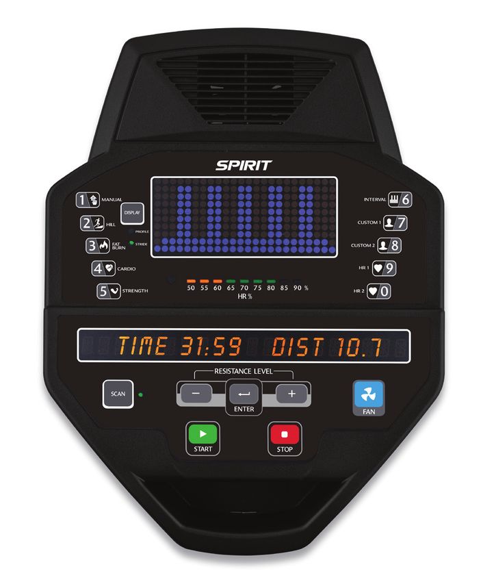
15CE850 CONSOLE OPERATION
Fan to keep
you cool
Ten innovative
Large Blue-LED programs offer a
Matrix Window variety of work-outs
Heart Rate % Profile
20-Character
Message Center
Easy-Touch
Control Buttons
Convenient cargo
compartment for
keys, phone, or
MP3 player
16POWER When the A.C. power cord is connected to the Elliptical, the console will automatically power up. In stand-by mode the console display will turn off. To turn the console on press any key. When initially powered on the console will perform an internal self-test. During this time all the lights will turn on. When the lights go off, the Message Center will show the software version (i.e.: VER 1.0). The window shows the distance total and total hours of use. The odometer will remain displayed for only a few seconds then the console will go to the start up display. The dot matrix display will be scrolling through the different profiles of the programs and the Message Center will be scrolling the start up message. You may now begin to use the console. Quick Start This is the quickest way to start a workout. After the console powers up you just press the Start key to begin. This will initiate the Quick Start mode. In Quick Start the Time will count up from zero, all workout data will start to accrue and the workload may be adjusted manually by pressing the Up and Down buttons. The dot matrix display will show a ¼ mile (0.4km) track display or just the bottom row lit at first, depending on how the display button has been set (see Basic information below). As you increase the workload more rows will light indicating a harder workout. The Elliptical will get harder to pedal as the rows increase. The dot matrix has 24 columns of lights and each column represents 1 minute. At the end of the 24th column (or 24 minutes of work) the display will wrap around and start at the first column again. There are 20 levels of resistance – displayed as 10 rows of lights - available for plenty of variety. The first 5 levels are very easy workloads, and the changes between levels are set to a good progression. 17
for de-conditioned users. Levels 5-10 are more challenging but the increases from one level to the next
     remain small. Levels 10-15 start getting tough as the levels jump more dramatically. Levels 15-20 are
     extremely hard and are good for short interval peaks and elite athletic training.

     Basic Information
     The Dot Matrix, or Profile Window, has two display modes. When you begin a program the dot matrix
     will display the workout Profile. To the left of the dot matrix there is a button labeled Display. Pressing
     this button once will switch the display to show a quarter mile track. If the Display button is pressed
     again the dot matrix will switch back and forth between Track and Profile mode every few seconds. To
     turn off the scan mode press the Display key again. This will return you to the profile display mode.
     The Message Window will initially be displaying Time and Distance information. On the bottom left
     of the Message Window is a button labeled Display. Each time this Display button is pressed the
     next set of information will appear, four windows in all. In order: Time and Distance, Pulse and Kcal
     (Calories), Speed in RPM and MPH, Work Level and Watts, then METs. If the Display button is
     pressed during the METs display the Scan light will come on and the Message Window will show
     each set of data for four seconds then switch to the next set of data in a continuous loop. Pressing the
     Display button again will bring you back to the beginning.
     Below the Dot matrix display is a Heart Icon and a Bar Graph. The Elliptical has a built in heart
     rate monitoring system. Simply grasping the hand pulse sensors, or wearing a heart rate chest belt
     transmitter, will start the Heart Icon blinking (this may take a few seconds). The Message Window will
     display your heart rate, or Pulse, in beats per minute. The Bar Graph represents the percentage of your
     maximum heart rate you are currently achieving. NOTE: You must enter your age during program setup
18
for the Bar Graph to be accurate. Refer to Heart Rate section for details about these features and how
they can help you work out more efficiently.
The Stop/Reset button actually has several functions. Pressing the Stop/Reset key once during a
program will pause the program for 5 minutes (when you stop pedaling without AC power the display
will turn off but the memory will be saved for 5 minutes just like the pause mode). If you need to get
a drink, answer the phone, or any of the many things that could interrupt your workout, this is a great
feature. To resume your workout during Pause just press the Start key or start pedaling. If the Stop/
Reset button is pressed twice during a workout the program will end and the console will return
to the start up screen. If the Stop/Reset key is held down for 3 seconds the console will perform
a complete Reset. During data entry for a program the Stop/Reset key performs a Previous Screen
function. This allows you to go back one step in the programming each time you press the Stop/Reset
key.
The Program Keys are used to preview each program. When you first turn the console on you may
press each program key to preview what the program profile looks like. If you decide that you want
to try a program, press the corresponding program key and then press the Enter key to select the
program and enter into the data-setup mode.
The program keys also act as a Number Key Pad when you are in the data-setup mode. Under each
program key is a number. If you are setting new data such as age, weight etc., you can use these keys to
enter the numbers quickly.
The console includes a built-in fan to help keep you cool. To turn the fan on press the key on the right
side, front of the console
19Programming The Console
Each of the programs can be customized with your personal information and changed to suit your
needs. Some of the information asked for is necessary to ensure the readouts are correct. You will be
asked for your Age and Weight. Entering your Age ensures that the Heart Rate bar graph shows
the correct number. Your Age is also necessary during the Heart Rate control program to ensure the
correct settings are in the program for your Age. Otherwise the work settings could be too high or
low for you; entering your Weight aides in calculating a more correct Calorie reading. Although we
cannot provide an exact calorie count we do want to be as close as possible.
CALORIE NOTE: Calorie readings on every piece of exercise equipment, whether it is in a gym or at home, are not
accurate and tend to vary widely. They are meant only as a guide to monitor your progress from workout to workout. The
only way to measure your calorie burn accurately is in a clinical setting connected to a host of machines. This is because
every person is different and burns calories at a different rate. Some good news is that you will continue to burn calories at
an accelerated rate for at least an hour after you have finished exercising!
Entering A Program & Changing Settings
When you enter a program (by pressing a program key, then Enter key) you have the option of
entering your own personal settings. If you want to workout without entering new settings then just
press the Start key. This will bypass the programming of data and take you directly to the start of your
workout. If you want to change the personal settings then just follow the instructions in the Message
Window. If you start a program without changing the settings the default - or pre-saved – settings will
be used.
20Stride Length Adjustment
The CE850 has a unique adjustable stride length feature that will further increase the variety of your
workouts. When the stride setting is at its lowest (shortest) position the stride length will be 18 inches.
This setting is used when pedaling slowly, during quick bursts at very high resistance, and to closely
simulate a walking motion. The highest (longest) setting is 24 inches and closely simulates the longer
stride of a running motion. The stride adjustment can also be used to select a stride length that is
comfortable for you. The stride length can also be computer controlled in some programs. The stride
length can be controlled by buttons on the left swing arm and also can be automatically adjusted during
the built-in workout programs.
MANUAL
The Manual program works as the name implies, manually. This means that you control the workload
yourself and not the computer. To start the Manual program follow the instructions below or just press
the Manual button then the Enter button and follow the directions in the
Message Window.
1. Press the Manual key then press the Enter key.
2. The Message Window will ask you to enter your Age. You may enter your Age, using the Up and Down keys or the
numeric key pad, then press the Enter key to accept the new number and proceed on to the next screen.
3. You are now asked to enter your Weight. You may adjust the Weight number using the Up and Down keys, or the
numeric key pad, then press enter to continue.
4. The next setting is Time. You may adjust the Time and press enter to continue.
5. Now you are finished editing the settings and can begin your workout by pressing the Start key. You can also go back
21and modify your settings by pressing the Enter key.
NOTE: At any time during the editing of data you can press the Stop key to go back one level, or screen.
6. The program automatically starts you at level one. This is the easiest level and it is a good idea to stay at level one for a
while to warm up. If you want to increase the work load at any time press the Up key; the Down key will decrease the
workload.
7. During the Manual program you will be able to scroll through the data in the Message Window by pressing the
adjacent Display key. You may also switch between the profile display and a quarter mile track by pressing the Display
key adjacent to the dot matrix display.
8. When the program ends you may press Start to begin the same program again or Stop to exit the program, or
you can save the program you just completed as a custom program by pressing the Custom key and following the
instructions in the Message Window.
22Preset Programs
The elliptical trainer has seven different programs that have been designed for a variety of workouts.
These five programs have factory preset work level profiles for achieving different goals.
HILL
This program follows a triangle or pyramid type of gradual progression from approximately 10% of maximum effort (the level
that you chose before starting this program) up to a maximum effort which lasts for 10% of the total workout time, then a
gradual regression of resistance back to approximately 10% of maximum effort
RESISTANCE LEVEL
FAT BURN
This program follows a quick progression up to the maximum resistance level (default or user input level) that is sustained for
2/3 of the workout. This program will challenge your ability to sustain your energy output for an extended period of time.
RESISTANCE LEVEL
23CARDIO
This program presents a quick progression up to near maximum resistance level (default or user input level). It has slight
fluctuations up and down to allow your heart rate to elevate, and then recover repeatedly, before beginning a quick cool
down. This will build up your heart muscle and increase blood flow and lung capacity
RESISTANCE LEVEL
STRENGTH
This program has a gradual progression of resistance up to 100% of maximum effort that is sustained for 25% of workout
duration. This will help build strength and muscular endurance in the lower body and glutes. A brief cool down follows.
RESISTANCE LEVEL
24INTERVAL
This program takes you through high levels of intensity followed by recovery periods of low intensity. This program utilizes
and develops your “Fast Twitch” muscle fibers which are used when performing tasks that are intense and short in duration.
These deplete your oxygen level and spike your heart rate, followed by periods of recovery and heart rate drop to
replenish oxygen. Your cardiovascular system gets programmed to use oxygen more efficiently.
RESISTANCE LEVEL
25Programming Preset Programs
1. Select the desired program button then press the Enter key.
2. The Message Window will ask you to enter your Age. You may adjust the age setting, using the Up and Down keys,
then press the Enter key to accept the new number and proceed on to the next screen.
3. You are now asked to enter your Weight. You may adjust the weight number using the Up and Down keys, then press
Enter to continue.
4. Next is Time. You may adjust the Time and press Enter to continue.
5. Now you are asked to adjust the Max Level. This is the peak exertion level you will
experience during the program (at the top of the hill). Adjust the level and then press Enter.
6. Now you are finished editing the settings and can begin your workout by pressing the Start key. You can also go back
and modify your settings by pressing the Stop key to go back one level, or screen.
7. If you want to increase or decrease the workload at any time during the program press the Up or Down key. This
will change the workload settings of the entire profile, although the profile picture on the screen will not change. The
reason for this is so that you can see the entire profile at all times. If the profile picture is changed it will look distorted
and not a true representation of the actual profile. When you make a change to the workload, the
Message Window will show the current column, and program maximum, levels of work.
8. During the program you will be able to scroll through the data in the Message Window by pressing the Display key
next to the Message Window.
9. When the program ends the Message Window will show a summary of your
workout. The summary will be displayed for a short time then the console will
return to the start-up display.
Custom User Defined Programs
The Custom Program allows you to build and save a custom program. You can build your own custom
program by following the instructions below or you can save any other preset program you complete
as a custom program. The Custom Program allows you to further personalize it by adding your facility
26 name.1. Press the Custom key. The Message Window will show a welcome message; if you had previously saved a program
the message will contain the name you gave it. Then press the Enter key to begin programming.
2. When you press Enter, the Message Window will show “Name – A”, if there is no name saved. If the name “Custom
Workout” had been previously saved the Message
Window will show “Name – Custom Workout” and the C in Custom will be blinking. If there is a name saved you can
change it or you may press the Stop key to keep the name and continue to the next step. If you want to enter a name
use the Up and/or the Down key to change the first letter then press Enter to save the first letter and continue to
the next letter. When you have finished entering the name press the Stop key to save the name and continue to the
next step.
3. The Message Window will ask you to enter your Age. You may enter your Age, using the Up and Down keys or the
numeric key pad, then press the Enter key to accept the new number and proceed on to the next screen.
4. You are now asked to enter your Weight. You may adjust the Weight number using the Up and Down keys or the
numeric key pad then press enter to continue.
5. Next is Time. You may adjust the Time and press Enter to continue.
6. Now you are asked to adjust the Max Level and Max Stride. This is the peak exertion level you will experience
during the program. Adjust the level and then press Enter.
7. Now the first column will be blinking and you are asked to adjust the level for the first segment of the workout. When
you finish adjusting the first segment, or if you don’t want to change, then press Enter to continue to the next segment.
8. The next segment will show the same level as the previously adjusted segment. Repeat the same process as the last
segment then press Enter. Continue this process until all twenty segments have been set.
9. The Message Window will then tell you to press Enter to save the program. After saving the program the Message
Window says “New program saved” then will give you the option to start or modify the program. Pressing Stop will
exit to the start up screen.
10. If you want to increase or decrease the workload at any time during the program press the Up or Down key. This will
only affect the workload for the present position in the profile. When the profile changes to the next column it will
return to the preset work level.
11. During the User 1 or User 2 program you will be able to scroll through the data in the Message Window by pressing
the adjacent Display key, switch between the profile display and a quarter mile track by pressing the Display key
adjacent to the matrix, use the heart rate monitoring features and can switch to heart rate Auto-Pilot mode. See Heart 27
Rate section for details of this feature).Heart Rate Programs
The old motto, “no pain, no gain”, is a myth that has been overpowered by the benefits of exercising
comfortably. A great deal of this success has been promoted by the use of heart rate monitors. With
the proper use of a heart rate monitor, many people find that their usual choice of exercise intensity
was either too high or too low and exercise is much more enjoyable by maintaining their heart rate in
the desired benefit range.
To determine the benefit range in which you wish to train, you must first determine your Maximum
Heart Rate. This can be accomplished by using the following formula: 220 minus your age. This will give
you the Maximum Heart Rate (MHR)for someone of your age. To determine the effective heart rate
range for specific goals you simply calculate a percentage of your MHR. Your Heart rate training zone is
50% to 90% of your maximum heart rate. 60% of your MHR is the recommended for burning fat while
80% is recommended for strengthening the cardio vascular
system. This 60% to 80% is the zone to stay in for maximum
benefit.
For someone who is 40 years old their
target heart rate zone is calculated:
220 – 40 = 180 (maximum heart rate)
180 x .6 = 108 beats per minute (60% of maximum)
180 X .8 = 144 beats per minute (80% of maximum)
So for a 40 year old the training zone would
be 108 to 144 beats per minute.
28If you enter your age during programming the console will perform this calculation automatically.
Entering your age is used for the Heart Rate programs. After calculating your MHR you can decide
upon which goal you would like to pursue.
The two most popular reasons for, or goals, of exercise are cardiovascular fitness (training for the heart
and lungs) and weight control. The black columns on the chart above represent the MHR for a person
whose age is listed at the bottom of each column. The training heart rate, for either cardiovascular
fitness or weight loss, is represented by two different lines that cut diagonally through the chart. A
definition of the lines’ goal is in the bottom left-hand corner of the chart. If your goal is cardiovascular
fitness or if it is weight loss, it can be achieved by training at 80% or 60%, respectively, of your MHR
on a schedule approved by your physician. Consult your physician before participating in any exercise
program.
With all Spirit Fitness Heart Rate programs you may use the heart rate monitor feature without using
the Heart Rate program. This function can be used during manual mode or during any of the nine
different programs. The Heart Rate program automatically controls resistance at the pedals.
29Rate of Perceived Exertion
Heart rate is important but listening to your body also has a lot of advantages. There are more
variables involved in how hard you should workout than just heart rate. Your stress level, physical health,
emotional health, temperature, humidity, the time of day, the last time you ate and what you ate, all
contribute to the intensity at which you should workout. If you listen to your body, it will tell you all of
these things.
The rate of perceived exertion (RPE), also know as the Borg scale, was developed by Swedish
physiologist G.A.V. Borg. This scale rates exercise intensity from 6 to 20 depending upon how you feel
or the perception of your effort.
The scale is as follows:
Rating Perception of Effort
6 Minimal 10 Very light + 14 Somewhat hard + 18 Very hard +
7 Very,very light 11 Fairly light 15 Hard 19 Very,very hard
8 Very,very light + 12 Comfortable 16 Hard + 20 Maximal
9 Very light 13 Somewhat hard 17 Very hard
You can get an approximate heart rate level for each rating by simply adding a zero to each rating. For example a
rating of 12 will result in an approximate heart rate of 120 beats per minute. Your RPE will vary depending up the
factors discussed earlier. That is the major benefit of this type of training. If your body is strong and rested, you will feel
strong and your pace will feel easier. When your body is in this condition, you are able to train harder and the RPE will
support this. If you are feeling tired and sluggish, it is because your body needs a break. In this condition, your pace will
feel harder. Again, this will show up in your RPE and you will train at the proper level for that day.
30Wearing The Chest Strap *Not Included
1. Attach the transmitter to the elastic strap using the interlocking key.
2. Adjust the strap as tightly as possible as long as the strap is not too tight to remain
comfortable.
3. Position the transmitter with the logo centered in the middle of your torso facing away
from your chest (some people must position the transmitter slightly left of center). Attach
the final end of the elastic strap by inserting the round end and, using the locking parts,
secure the transmitter and strap around your chest.
4. Position the transmitter directly below the pectoral muscles.
5. Sweat is the best conductor to measure very minute heart beat electrical signals. However,
plain water can also be used to pre-wet the electrodes (2 ribbed oval areas on the reverse
side of the belt and both sides of the transmitter). It’s also recommended that you wear
the transmitter strap a few minutes before your work out. Some users, because of body chemistry, have a more difficult
time in achieving a strong, steady signal at the beginning. After “warming up”, this problem lessens.
6. Your workout must be within range - distance between transmitter/receiver – to achieve a strong steady signal. The
length of range may vary somewhat but generally stay close enough to the console to maintain good, strong, reliable
readings. Wearing the transmitter directly on bare skin assures you of proper operation. If you wish, you may wear the
transmitter over a shirt. To do so, wet the areas of the shirt that the electrodes will rest upon.
Note:The transmitter is automatically activated when it detects activity from the user’s heart. Additionally, it automatically deactivates when it
does not receive any activity. Although the transmitter is water resistant, moisture can have the effect of creating false signals, so you should take
precautions to completely dry the transmitter after use to prolong battery life (estimated transmitter battery life is 2500 hours).The replacement
battery is Panasonic CR2032.
31Erratic Operation
Caution! Do not use this Elliptical for Heart Rate programs unless a steady, solid Actual Heart Rate
value is being displayed. High, wild, random numbers being displayed
indicate a problem.
Areas to look for interference which may cause erratic heart rate:
1. Microwave ovens, TV’s, small appliances, etc.
2. Fluorescent lights.
3. Some household security systems.
4. Perimeter fence for a pet.
5. Some people have problems with the transmitter picking up a signal from their skin. If you have problems try wearing
the transmitter upside down. Normally the transmitter will be oriented so the Spirit Fitness logo is right side up.
6. The antenna that picks up your heart rate is very sensitive. If there is an outside noise source,
turning the whole machine 90 degrees may de-tune the interference.
7. Another Individual wearing a transmitter within 3’ of your machine’s console.
If you continue to experience problems contact your dealer.
Heart Rate Program Operation
To start the HR program follow the instructions below or just press the HR key then the Enter button
and follow the directions in the Message Window.
1. Press the HR key then press the Enter key.
2. The message window will ask you to enter your Age. You may enter your Age, using the Up/Down keys or the numeric
key pad, then press the Enter key to accept the new number and proceed on to the next screen.
323. You are now asked to enter your Weight. You may adjust the Weight number using the Up/Down keys or the numeric
key pad, then press Enter to continue.
4. Next is Time. You may adjust the Time and press Enter to continue.
5. Now you are asked to adjust your target Heart Rate. This is the heart rate level you will try to maintain during the
program. Adjust the value and then press Enter.
6. Now you are finished editing the settings and can begin your workout by pressing the Start key. You can also go back
and modify your settings by pressing the Enter key. Note: At any time during the editing of data you can press the Stop
key to go back one level, or screen.
7. If you want to increase or decrease the resistance at any time during the program press the Up/Down key. This will
allow you to change your target heart rate at any time during the program.
8. The program will automatically increase or decrease the amount of resistance, depending on whether your heart rate is
above or below your target.
9. During the HR program you will be able to scroll through the data in the Message Window by pressing the adjacent
Display key.
10. When the program ends you may press Start to begin the same program again or Stop to exit the program or
you can save the program you just completed as a custom user program by pressing a User key and following the
instructions in the Message Window.
Engineering Mode
Maintenance Menu in console software:
The console has built in maintenance/diagnostic software. The software will allow you to change the console
settings from English to Metric and turn off the beeping of the speaker when a key is pressed for example. To
enter the Maintenance menu (may be called Engineering mode, depending on version) press and hold down
the Start, Stop and Enter keys. Keep holding the keys down for about 5 seconds and the message window will
display ENGINEERING MODE MENU PRESS ENTER. Press the enter button to access the menu below:
33a. Key test(will allow you to test all the keys to make sure they are functioning)
b. Display test (tests all the display functions)
c. Functions (Press enter to access settings)
i. Sleep mode (Turn on to have the console power down automatically after 30 minutes of inactivity)
ii. Pause Mode (Turn on allow 5 minutes of pause, turn off to have the console pause indefinitely)
iii. ODO reset (reset the odometer)
iv. Units (Set to English or Metric display readings)
v. Beep (Turn on or off the beep when a key is pressed)
vi. D/A test (tests the brake resistance)
vii. SAFETY
d. Security (Allows you to lock the keypad so no unauthorized use is allowed)
Stride Calibration: If there is a problem with the stride, try running the calibration. Press the Start key and
Level up key at the same time. Hold them down for 5 seconds and the stride calibration, press Enter and run
automatically. If the problem persists, contact service department.
GENERAL MAINTENANCE
8. Wipe down all areas in the sweat path with a damp cloth after each workout.
9. If a squeak, thump, clicking or rough feeling develops the main cause is most likely one of two reasons:
I. The hardware was not sufficiently tightened during assembly. All bolts that were installed
during assembly need to be tightened as much as possible. It may be necessary to use a larger wrench than the
one provided if you cannot tighten the bolts sufficiently. I cannot stress this point enough; 90% of calls to the ser-
vice department for noise issues can be traced to loose hardware.
II. The crank arm nut needs to be retightened
III. If squeaks or other noises persist, check that the unit is properly leveled. There are 2 leveling pads on the bottom
34 of the rear stabilizer, use a 14mm wrench (or adjustable wrench) to adjust the levelers.Elliptical Trainer Warranty - Effective December 23, 2015
Spirit Fitness, Inc. (Spirit Fitness) warrants all its elliptical trainer parts for a period of time listed below from the date of retail sale, as determined by sale
receipt, or in the absence of a sales receipt eighteen (18) months from the original factory shipping date. Spirit Fitness’ responsibilities include providing new or
remanufactured parts, at Spirit Fitness’ option, and technical support to our independent dealers and servicing organizations.
In the absence of a dealer or service organization, these warranties will be administered by Spirit Fitness directly to a consumer.
The warranty period applies to the following components:
Warranty Frame Brake Parts Labor
Light Commercial (5 Hours use or less in a Lifetime 5 Years 5 Years 2 Years
non-dues paying facility)
Residential Lifetime 10 Years 10 Years 2 Years
NORMAL RESPONSIBILITIES OF THE CONSUMER
This warranty applies only to products in ordinary household or Light Commercial use (see restrictions above), and the consumer/facility is responsible for
the items listed below:
1. The warranty registration card must be completed and returned to the address listed on the card within 10 days of the original purchase to validate
the manufacturer’s limited warranty.
2. Proper use of the elliptical trainer in accordance with the instructions provided in this manual
3. Proper installation in accordance with instructions provided with the elliptical trainer and with all local electric codes.
4. Expenses for making the elliptical trainer accessible for servicing, including any item that was not part of the elliptical trainer at the time it was shipped
from the factory.
5. Damages to the elliptical trainer finish during shipping, installation or following installation.
6. Routine maintenance of this unit as specified in this manual.
EXCLUSIONS
This warranty does not cover the following:
1. CONSEQUENTIAL, COLLATERAL, OR INCIDENTAL DAMAGES SUCH AS PROPERTY DAMAGE AND INCIDENTAL EXPENSES
RESULTING FROM ANY BREACH OF THIS WRITTEN OR ANY IMPLIED WARRANTY.
Note: Some states do not allow the exclusion or limitation of incidental or consequential damages, so this limitation or exclusion may not apply to
you.
2. Service call reimbursement to the consumer. Service call reimbursement to the dealer that does not involve malfunction or defects in workmanship
or material, for units that are beyond the warranty period, for units that are beyond the service call reimbursement period, for elliptical trainer not
requiring component replacement, or elliptical trainer not in ordinary household or light commercial use.
3. Damages caused by services performed by persons other than authorized Spirit Fitness service companies; use of parts other than original Spirit
Fitness parts; or external causes such as corrosion, discoloration of paint or plastic, alterations, modifications, abuse, misuse, accident, improper
maintenance, inadequate power supply, or acts of God.
4. Products with original serial numbers that have been removed or altered.
355. Products that have been: sold, transferred, bartered, or given to a third party.
6. Products that do not have a warranty registration card on file at Spirit Fitness. Spirit Fitness reserves the right to request proof of
purchase if no warranty record exists for the product.
7. THIS WARRANTY IS EXPRESSLY IN LIEU OF ALL OTHER WARRANTIES EXPRESSED OR IMPLIED, INCLUDING THE WARRANTIES OF MER-
CHANTABILITY AND/OR FITNESS FOR A PARTICULAR PURPOSE.
8. Product use in any environment other than a residential setting or non-dues paying facility with 5 hours use or less per day.
9. Warranties outside of the United States may vary. Please contact your local dealer for details.
SERVICE
Keep your bill of sale. Twelve (12) months from the date on the bill of sale or eighteen (18) months from the date of factory shipping as
determined by the serial number establishes the labor warranty period should service be required. If service is performed, it is in your best
interest to obtain and keep all receipts. This written warranty gives you specific legal rights. You may also have other rights that vary from
state to state. Service under this warranty must be obtained by following these steps, in order:
1. Contact your selling authorized Spirit Fitness dealer. OR
2. Contact your local authorized Spirit Fitness service organization.
3. If there is a question as to where to obtain service, contact our service department at (870) 935-1107.
4. Spirit Fitness’ obligation under this warranty is limited to repairing or replacing, at Spirit Fitness’ option, the product through one of our authorized
service centers. All repairs must be preauthorized by Spirit Fitness. If the product is shipped to a service center freight charges to and from the
service
center will be the customer’s responsibility. For replacement parts shipped while the product is under warranty, the customer will be
responsible for shipping and handling charges. For in-home service, the customer will be responsible for a trip charge. There will be an
additional trip charge if the customer is located over 100 miles from the nearest service center.
5. The owner is responsible for adequate packaging upon return to Spirit Fitness. Spirit Fitness is not responsible for damages in shipping. Make all freight
damage claims with the appropriate freight carrier. DO NOT SHIP ANY UNIT TO OUR FACTORY WITHOUT A RETURN AUTHORIZATION
NUMBER. All units arriving without a return authorization number will be refused.
6. For any further information, or to contact our service department by mail, send your correspondence to:
Spirit Fitness, Inc.
P.O. Box 2037
Jonesboro, AR 72402-2037
Product features or specifications as described or illustrated are subject to change without notice. All warranties are made by Spirit Fitness, Inc. This warran-
ty applies only in the 48 contiguous United States. NOTE: This does not apply to Alaska or Hawaii.
36NOTES
37NOTES 38
39
800.258.4555                      Spirit Fitness
spiritservice@spiritfitness.com   3000 Nestle Road
www.spiritfitness.com             Jonesboro, AR 72401

                                  CE850 Owners Manual
                                  © 2015 All Rights Reserved
                                  Revision: 12 .23. 2015
You can also read