Boundary curvature guided programmable shape-morphing kirigami sheets
←
→
Page content transcription
If your browser does not render page correctly, please read the page content below

ARTICLE
                  https://doi.org/10.1038/s41467-022-28187-x                 OPEN

                  Boundary curvature guided programmable
                  shape-morphing kirigami sheets
                  Yaoye Hong           1,   Yinding Chi1, Shuang Wu1, Yanbin Li1, Yong Zhu1 & Jie Yin                            1✉

                  Kirigami, a traditional paper cutting art, offers a promising strategy for 2D-to-3D shape
                  morphing through cut-guided deformation. Existing kirigami designs for target 3D curved
1234567890():,;

                  shapes rely on intricate cut patterns in thin sheets, making the inverse design challenging.
                  Motivated by the Gauss-Bonnet theorem that correlates the geodesic curvature along the
                  boundary with the Gaussian curvature, here, we exploit programming the curvature of cut
                  boundaries rather than the complex cut patterns in kirigami sheets for target 3D curved
                  morphologies through both forward and inverse designs. The strategy largely simplifies the
                  inverse design. Leveraging this strategy, we demonstrate its potential applications as a uni-
                  versal and nondestructive gripper for delicate objects, including live fish, raw egg yolk, and a
                  human hair, as well as dynamically conformable heaters for human knees. This study opens a
                  new avenue to encode boundary curvatures for shape-programing materials with potential
                  applications in soft robotics and wearable devices.

                  1 Department   of Mechanical and Aerospace Engineering, North Carolina State University, Raleigh, NC 27695, USA. ✉email: jyin8@ncsu.edu

                  NATURE COMMUNICATIONS | (2022)13:530 | https://doi.org/10.1038/s41467-022-28187-x | www.nature.com/naturecommunications                   1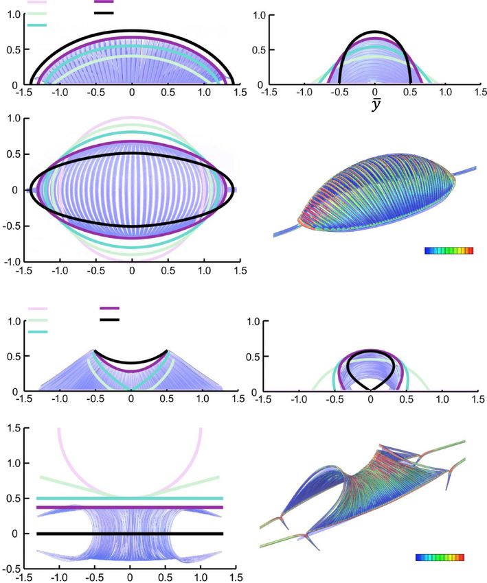
ARTICLE                                                                  NATURE COMMUNICATIONS | https://doi.org/10.1038/s41467-022-28187-x

D
          esigning shape-programming materials from 2D thin                   objects and a biomimetic conformable heating pad with
          sheets to 3D shapes has attracted broad and increasing              intrinsic adaptivity for human knees.
          interest in the past decades due to their novel materials
properties imparted by geometrical shapes1. Programmable shape                Results
shifting in different materials and structures was realized at all            Manipulating 2D boundary curvatures for 3D curved
scales utilizing folding, bending, and buckling2. These shape-                morphologies. The classical Gauss–Bonnet theorem37 correlates
programmable materials are attractive for broad applications in               the boundary curvature with the global Gaussian curvature K.
programmable machines and robots3,4, functional biomedical                    Motivated by the theorem, as shown in Fig. 1a–f, we start by
devices5, and four-dimensional (4D) printing6,7.                              designing the 2D precursors of kirigami sheets with different
   Kirigami, the traditional art of paper cutting, has recently emerged       boundary curvatures kbo to exploit its effects on the Gaussian
as a new promising approach for creating shape morphing structures            curvature of their 3D deployed shapes, where kbo is set to be
and materials8–19. Cuts divide the original continuous thin sheets            positive (circular boundary in Fig. 1a), zero (rectangular bound-
into discretized cut units without sacrificing the global structural           ary in Fig. 1b), and negative (biconcave circular boundary in
integrity. Compared to continuous thin sheets, the kirigami sheet             Fig. 1c), respectively. We use the polyethylene terephthalate
enables more freedom and flexibility in shape shifting through local           (PET) sheet with Young’s modulus of 3.5 GPa, Poisson’s ratio of
or global deformation between cut units17. Starting from a thin sheet         0.38, and thickness of 127 μm to fabricate the kirigami sheets
with patterned cuts, it can morph into varieties of 2D and pop-up             using laser cutting (see “Methods” section). The thin sheets are
3D structures via rigid rotation mechanism20 and/or out-of-plane              cut into a number of discrete parallel thin ribbons enclosed by
buckling21. The cuts impart new properties such as auxeticity9,11,            continuous boundary ribbon.
stretchability8,10,15,22–24, conformability8, multistability25, and opti-        Figure 1d–f show that stretching the 2D precursors leads to
cal chirality26, which have found broad applications in mechanical            distinct spheroidal, cylindrical, and saddle shapes with positive,
metamaterials11,15,27,28, stretchable devices8,10,23,29,30, 3D mechan-        zero, and negative Gaussian curvature K, respectively (Supple-
ical self-assembly31, tunable adhesion32, and soft machines17,18,33.          mentary Movie 1). Upon stretching, the boundary ribbon starts
   Despite the advance, most studies focus on the local buckling              bending and compresses the enclosed discrete ribbons to induce
of cut units in a thin sheet patterned with arrays of parallel slits or       their out-of-plane buckling. Thus, it renders a 3D pop-up
networked triangular or square cuts etc8–13,15,17,18, generating              morphology. Once the 3D shape is formed, the global shape will
quasi-3D pop-up structures without global curvatures. There are               not change but with its magnitude of curvature increasing with
few studies on the shape shifting from a kirigami sheet to 3D                 the applied strain. The three samples exhibit similar J-shaped
shapes with intrinsic curvature34–36. Recent work shows that                  force–displacement curves as shown in Fig. 1g, where the force
starting from a kirigami sheet or shell, 3D shapes with non-zero              increases approximately linearly with the initial displacement due
Gaussian curvature can be generated by utilizing either forward               to the bending-dominated deformation in the discrete ribbons,
designs of non-periodic patterns of square cuts/cutouts34,36                  followed by the steep rise arising from the stretching-dominated
or inverse designs of tessellation of non-uniform square cuts                 deformation in the boundary ribbon. Such stiffness strengthening
patterning with irregular polygon cut units35. The local hetero-              mechanical responses are similar to that observed in the kirigami
geneous deformation among non-periodic tessellated cut units                  sheet patterned with orthogonal square cuts24. Among the
induces global out-of-plane buckling of the 2D kirigami sheets,               three samples, the circular one morphing into a spheroidal shape
thus, resulting in the formation of different 3D curved                       shows the highest stiffness and the least stretchability, while the
shapes34,35. However, it often requires programming intricate cut             biconcave one deforming into a saddle shape is the most
patterns and arrangements of non-periodic cut units, making the               compliant and stretchable (Fig. 1g).
inverse design and optimization for target 3D shapes complicated                 We note that distinct from the kirigami sheets composed of
and challenging35,36. In addition, how to utilize the 3D curved               networked polygon cut units in previous studies8,11,34–36 or
shapes in kirigami sheets for functionalities remains largely                 discrete structures composed of disconnected non-geodesic
unexplored34–36.                                                              ribbons38, the simple design of parallel cuts in this work endows
   Theoretically, the curvature of a boundary can be harnessed                the unique characteristic, i.e., parallel cuts make each discrete
to tune 3D curved shapes based on the classical Gauss-Bonnet                  ribbon a geodesic curve of the morphed morphologies (see
theorem in differential geometry37, which correlates the                      “Methods” section). It will facilitate the inverse design and
Gaussian curvature and the geodesic curvature along the                       dynamically programming morphologies, as discussed later.
boundary (i.e., the projection of boundary curvature). Moti-                     By extending the classical Gauss–Bonnet theorem in differ-
vated by this theorem, here, we propose a simple strategy of                  ential geometry to the two neighboring enclosed ribbons and the
utilizing the boundary curvature of cut edges rather than                     multiple-connected enclosed kirigami surface morphology (Sup-
complex cut patterns to program 3D curved shapes through                      plementary Fig. 1 and see “Methods” section), we can
both forward and inverse designs. In contrast to previous net-                qualitatively explain the observed 3D curved shapes and their
worked polygon cut units with square cut patterning8,11,34–36,                dynamic shape morphing. Mathematically, for the morphed 3D
our kirigami sheet is composed of parallel discrete ribbons                   pop-up morphologies, the theorem can be simplified as
enclosed by continuous boundaries (Fig. 1a–c) through simple                                      Z           I
patterning of parallel cuts. We demonstrated that simply                                             KdA þ        kgb ds ¼ C;                 ð1Þ
stretching the kirigami sheet with prescribed curved cut                                               Ω             ∂Ω
boundaries could generate varieties of well-predicted 3D curved                                                             p
shapes with positive, negative, and zero Gaussian curvatures                  where the constant C ¼ 2πχðΩÞ  ∑i¼1 θi with χ(Ω) and θi
and their combinations. We proposed a straightforward inverse                 denoting the Euler characteristic of the Riemannian manifold Ω
design strategy for target 3D curved shapes, avoiding the                     with boundary ∂Ω and the exterior angles at the vertices of the
necessity of shape optimization by building on top of theore-                 manifold, respectively. C remains unchanged during shape shifting
tical insights from applying the Gauss–Bonnet theorem to                      (see “Methods” section). kgb ¼ kb sin φ is the geodesic curvature
the geodesic ribbons. Leveraging this, we demonstrated                        along the boundary ribbon according to the Meusnier theorem37,
their potential applications in designing a universal gripper                 i.e., the projection of the deformed boundary curvature kb with φ
with dynamically programmable morphology for delicate                         being the projection angle (see “Methods” section).

2                 NATURE COMMUNICATIONS | (2022)13:530 | https://doi.org/10.1038/s41467-022-28187-x | www.nature.com/naturecommunications
NATURE COMMUNICATIONS | https://doi.org/10.1038/s41467-022-28187-x                                                                          ARTICLE

                                 2D precursors before stretch                                 After stretch
                                              >                                                      >0
                             a                                                  d
                                                  1

                            stretch                                 stretch

                                                          ─
                                                              ─
                                         cut
                                                       =                                               =0
                             b                                                  e

                             c                        <                         f                       0 at an applied strain of 0.30. e Cylindrical shape with K = 0 at an applied strain of 0.65.
f Saddle shape with K < 0 at an applied strain of 1.47. Scale bars = 10 mm. g Force–displacement curves for the three 2D precursors. The shaded areas are
the standard deviation between four different tests.

                                                                                R              H           H           H
  For the 2D kirigami precursor H with positive boundary                                 ¼ C  ∂Ω0 kgb ds ¼ ∂Ω kgb ds  ∂Ω0 kgb ds in terms of
                                                                                    Ω0 KdA
curvature, i.e., kbo > 0, we have C ¼ ∂Ω kgb ds by setting K = 0
                                                                                                              o

                                        o                                       Eq. (1). As the applied strain increases, both kb and sin φ
with Ωo denoting the manifold before deformation. After                         decrease, which results
                                                                                                    R in a decreased geodesic curvature kgb,
deformation, for the deformed manifold Ω′, we have                              and consequently Ω0 KdA > 0. Given the C2 continuous

NATURE COMMUNICATIONS | (2022)13:530 | https://doi.org/10.1038/s41467-022-28187-x | www.nature.com/naturecommunications                                     3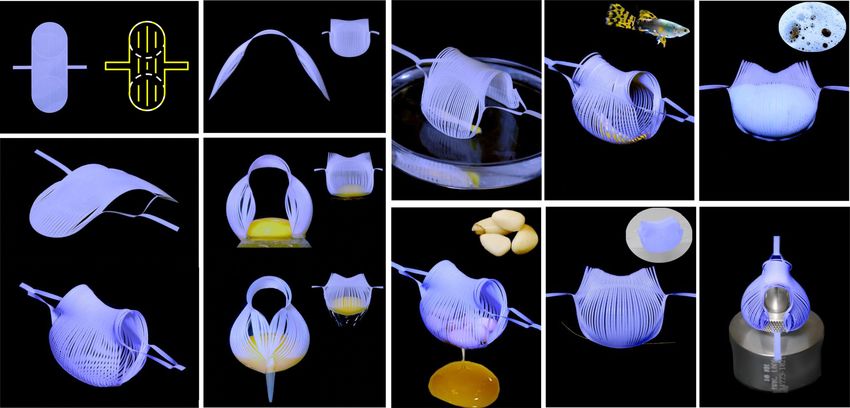
ARTICLE                                                                               NATURE COMMUNICATIONS | https://doi.org/10.1038/s41467-022-28187-x

boundary curves in the three characteristic precursors (C2                                 the xy plane during deformation by setting z = 0 in Eqs. (2–4),
continuity means that both the first and second derivatives of                              which can be parametrized by
the
R curves are continuous, i.e., continuous in curvature), both                                             r b ðsb ; εÞ ¼ ðx; y; 0Þ ¼ ðf ðsb ; εÞ; gðsb ; εÞ; 0Þ;   ð5Þ
  Ω0 KdA and K will be simultaneously positive or negative.
Thus, we have a globally positive K in the deformed manifold                               where
Ω′, i.e., K > 0 in Ω′, which is consistent with the observed
spheroidal shape in Fig. 1d. Similarly, for the 2D precursor                                                                2Eðπ2 ; mÞ
                                                                                                               gðsb ; εÞ ¼             1 gðsb ; 0Þ;                  ð6Þ
with kbo < 0, as the strain increases, the absolute value of                                                                 Fðπ2 ; mÞ
the boundary curvature jkb j becomes smaller and sin φ
decreases, which results in an increased geodesic curvature.                                describes the y coordinate at sb of the deformed boundary
Thus, we have the generated saddle shape with globally K < 0 in                             ribbon at the strain of ε. Equation (6) describes the relationship
Fig. 1f. For the 2D precursor with kbo = 0, during the                                      between m and ε. Thus, combining Eqs. (2–4) and Eq. (6) will
deformation, kbo = 0 does not change, which leads to a zero                                 determine the unknown parameters of x, y, z, and m to predict
geodesic curvature. Thus, we have a cylindrical shape with                                  the deformed 3D shapes with the applied strain. The side view
K = 0 in Fig. 1e.                                                                           shows the projection of similar elastica shapes of discrete
                                                                                            ribbons onto the yz plane (Fig. 2c, g and Supplementary
                                                                                            Fig. 5c), which depends on m and the tilting angle of the longest
 Analytical modeling and simulation on 3D shape shifting.
                                                                                            discrete ribbon. Its deformed elastica shape can be expressed by
 To quantify the shape shifting of the kirigami structures with
                                                                                           yd ¼ 2λEðAMðλsd ; mÞ; mÞ  sd and z d ¼ 2m            sd ; mÞ, where the
                                                                                                                                               λ CNðλ
 the applied strain, we combine both analytical modeling and
 finite element method (FEM) simulation to predict their mor-                                length of the discrete ribbons is assumed to be unchanged
 phology changes (see “Methods” section). The deformation of                                during deformation.
 the kirigami structures is dominated by bending of the discrete                                 Next, we apply both the generalized analytical model and FEM
 ribbons, where the elastic strain energy in the boundary ribbon                            simulation to analyze the 3D shape shifting in the specific
 is negligible due to its small width (Supplementary note 1).                               examples shown in Fig. 1. Figure 2a–c theoretically predict the
 Thus, all the discrete ribbons share similar deformed elastica                             variation of the three profiled shapes with the applied strain ε
 shapes39–42. The deformed 3D shape at an applied strain ε can                              during the formation of a spheroidal shape. As ε increases from 0
 be described by r s ðsb ;sd Þ ¼ ðxðsb ;sd Þ; yðsb ;sd Þ; z ðsb ;sd ÞÞ, where    to 0.4, top-view profiles show that the circular boundary gradually
sb and sd denote the normalized arc length coordinate of the                              deforms into an elliptical shape (Fig. 2b), where we have
 boundary and the discrete ribbon as illustrated in Fig. 1a,                                f ðsb ; εÞ ¼ ð1  w    Þ sin sb þ v cos sb    and        gðsb ; εÞ ¼ ð1
 respectively. ðx; y; zÞ denote the Cartesian coordinates of any                          Þ cos sb  v sin sb (sb 2 ½π2 ; π2 ) in the model (Supplementary
                                                                                            w
 point Pðsb ;sd Þ on the surface with its origin set at the center of                     note 1). w     ðsb ; εÞ and vðsb ; εÞ denote the radial and tangential
 the 2D precursor. Considering the deformed surface shape                                   displacement of the boundary ribbon43, respectively. Correspond-
 foliated by continuously varying discrete ribbons along the                                ingly, the compressed discrete ribbons deform into an elastica
 boundary, its generalized shape functions can be expressed as                              shape (side view in Fig. 2c). The backbone expands and shows an
 (see details in Supplementary note 1)                                                      elliptical profile (front view in Fig. 2a and Supplementary note 1).
                                                                                            As shown in Fig. 2a–c, the superposition of the three theoretically
                             2m
             xðsb ;sd Þ ¼    CNðλsd ; mÞ cos α1 þ f ðsb ; εÞ;                   ð2Þ    predicted front-view, top-view, and side-view profiles (high-
                              λ                                                             lighted in purple color) with images retrieved from the
                                     2                                                      experimental observation at ε = 0.3 shows an excellent agree-
                   yðsb ;sd Þ ¼     EðAMðλsd ; mÞ; mÞ  sd ;                   ð3Þ     ment. The corresponding FEM simulated deformed 3D shape
                                     λ
                                                                                            shows an excellent overlapping with the experiment (Fig. 2d).
                                 2m                                                         Differently, during the formation of the cylindrical shape, both
                     z ðsb ;sd Þ ¼CNðλsd ; mÞ sin α1 ;              ð4Þ                 the boundary ribbon and backbone profile remain straight during
                                  λ
                                                                                            deformation and all the discrete ribbons take the same elastic
by sweeping the varying discrete ribbons modeled as an elastica
                                                                                            shape, the modeling of which is consistent with both experiments
shape along the boundary. m ¼ mðsb ; εÞ is the elliptical modulus
                                                                                            and FEM simulation (Supplementary Fig. 5).
that characterizes the bending deformation of a discrete ribbon.
                                                                                                 Figure 2e–g show the predicted shape change during the
λ ¼ 2Fðπ2; mÞ=ld is related to the normalized length ld of the                            formation of a saddle shape. In contrast to simultaneous buckling
discrete ribbon. AM and CN denote the Jacobian amplitude and                                in generating the spheroidal and cylindrical shapes, we observe a
the elliptic cosine, respectively. E and F denote the incomplete                            sequential buckling during the formation of the saddle shape in
elliptic integral of the second kind and the first kind, respec-                             experiments (Supplementary Movie 1). The discrete ribbons near
tively. α1 ¼ α1 ðsb ; εÞ is the tilting angle of the discrete ribbon                       two stretching ends pop up first, followed by the ribbons in the
with respect to the horizontal plane (i.e., xy plane) as shown in                           center when beyond a critical strain εc (Supplementary Fig. 6).
Fig. 1d, which varies from 0 to 180° depending on its boundary                              The physical origin of the sequential buckling is due to the
location and the applied strain. f ðsb ; εÞ describes the x coordi-                        coupling effects of the concave boundary geometry and different
nate at sb of the deformed boundary ribbon.                                                critical buckling forces of the discrete ribbons (Supplementary
   Without losing generality, we can use three profiles from the                             note 1), where the curvature varies sequentially during deforma-
front view, top view, and side view to characterize the 3D shape                            tion along the boundary ribbon from its two ends to the center
shifting with the applied strain (Fig. 2a–c for spheroidal shapes,                          (Fig. 2f). Such sequential buckling behavior disappears for the
Fig. 2e–g for saddle shapes and Supplementary Fig. 5a–c for                                 large radius of curvature since the 2D precursor is close to a
cylindrical shapes). The front view shows the backbone profile                               rectangle shape. As the applied strain further increases, the
on the xz plane (Fig. 2a, e and Supplementary Fig. 5a), which                               discrete ribbons contact with each other, leading to structural
can be predicted by xbb ¼ 2m          λ cos α1 þ f ð sb ; εÞ and z bb ¼                  frustration. Reducing the number of ribbons facilitates a
2m
 λ  sin α 1 after setting
                             s d =  0 and
                                           y   =  0  in  Eqs. (2–4). The                    frustration-free structure without self-contact (Supplementary
top-view profile shows the deformed shape of the boundary                                    Fig. 7). Such a sequential shape shifting is well captured by both
ribbon (Fig. 2b, f and Supplementary Fig. 5b) that remains in                               the analytical model and FEM simulation. As predicted by the

4                      NATURE COMMUNICATIONS | (2022)13:530 | https://doi.org/10.1038/s41467-022-28187-x | www.nature.com/naturecommunications
NATURE COMMUNICATIONS | https://doi.org/10.1038/s41467-022-28187-x                                                                             ARTICLE

                        a         Theory                                            c
                                            0.00            0.30
                                            0.10            0.40
                                            0.20
                                                                         Sample

                        b                                                           d

                                                                                                      FEM
                                                                                             Sample

                                                                                                                                    0.30

                                                                                                                             0          0.4%

                        e         Theory
                                                                                    g
                                             0.00             1.47
                                             1.17             1.53
                                             1.42

                        f                                                           h

                                                                                                                                 1.47

                                                                                                                         0          0.6%

Fig. 2 Quantifying the 3D shape shifting through analytical modeling and simulation. a–h Predicted shape changes with the applied strain ε in the
samples of spheroidal (a–d) and saddle shapes (e–h). a, e Front-view profile. b, f Top-view profile. c, g Side-view profile. d, h Overlapping of FEM simulation
results (contours of the maximum principal strain εmax) with the experimental image at ε = 0.30 (d) and 1.47 (h). Scale bars = 10 mm.

model, Fig. 2f shows that at the critical strain εc ≈ 1.42, the initial                  and the Gaussian curvature K of their popped 3D morphologies
concave boundary ribbon deforms into a straight line and                                 at a given applied strain (see details in Supplementary Note 2).
remains straight upon furtherpdeformation,                      where   ffi we have
                                      ffiffiffiffiffiffiffiffiffiffiffiffiffiffiffiffiffiffiffiffiffiffiffiffiffiffiffiffiffiffiffiffiffiffiffi                Figure 3a, b show the theoretically predicted 3D maps of the
f ðsb ; εÞ ¼ sb and gðsb ; εÞ ¼ 1:46  ðε  0:32Þ with sb 2        2                 normalized Gaussian curvature K       at the center point Cðsb ¼
½1:32; 1:32 in the model (Supplementary Note 1). Correspond-                           0;sd ¼ 0Þ as a function of both normalized boundary curvature
ingly, the backbone profile (Fig. 2e) transits from an initial sharp                     k (see illustration of tuning different kbo in the insets of
                                                                                           bo
V shape to a smooth concave shape, which exhibits a sudden                               Fig. 3a, b) and applied strain ε. It shows that for 2D kirigami
jump of the displacement along the z-axis when the applied strain                        precursors with either positive (Fig. 3a) or negative boundary
is slightly beyond εc. Further stretching results in the formation of                    curvature (Fig. 3b), generally, the absolute value of K increases
the saddle shape with a concave backbone, which is consistent                            with an increasing strain ε and jkbo j. Note that for the
with both experiments (Fig. 2e–g) and FEM simulation results                             formed saddle shapes, we have K      = 0 before reaching the cri-
(Fig. 2h).                                                                                                                     suddenly decreases due to a
                                                                                         tical strain εc. At the onset of εc, K
                                                                                         dramatic increase in the boundary curvature. Beyond εc, K
Quantitative correlation between the boundary curvature and                              barely changes because the boundary ribbon remains straight
the Gaussian curvature. Based on the validated theoretical                               (Fig. 3b). Interestingly, Fig. 3c shows that theoretically,
model, we further establish the general quantitative correlation                         the normalized variation of Gaussian curvature jΔK=        K max j
between the boundary curvature kbo of 2D kirigami precursors                             increases approximately linearly with the normalized variation

NATURE COMMUNICATIONS | (2022)13:530 | https://doi.org/10.1038/s41467-022-28187-x | www.nature.com/naturecommunications                                    5
ARTICLE                                                                   NATURE COMMUNICATIONS | https://doi.org/10.1038/s41467-022-28187-x

     a                                                 b                                                  c        Experimental    Theoretical

                          C                                                    C

Fig. 3 Quantifying the correlation between the boundary curvature and the Gaussian curvature. a, b Theoretically predicted 3D maps of the normalized
Gaussian curvature K  at the center point C as a function of the normalized boundary curvature k in 2D kirigami precursors (insets) and the applied strain
                                                                                                  bo
ε for the cases of spherical (a) and saddle (b) shapes. The color bars represent the normalized Gaussian curvature. c Theoretical and experimental results
of the approximately linear relationship between the normalized variation of the Gaussian curvature jΔK=  K  j and the normalized variation of the
                                                                                                              max

boundary curvature jΔkb =kbo j.

of boundary curvature jΔkb =kbo j(slope ≈ 1) (Supplementary                  Gaussian curvature. This is also consistent with the Gauss-Bonnet
note 2), i.e.,                                                                 theorem, where the localized non-zero Gaussian curvature arises
                                                                               from the localized curvature change (variation of the exterior
             K
         jΔK=   max j                4m2 kbo                                 angle in Eq. (1)) of the C0 smooth inner and outer boundary
                     ¼  2                                  1;      ð7Þ
          jΔkb =kbo j                                    max
                         ½kbo x ðγ=kbo ; 0Þ  yð0; 1ÞK                      curves of the units (Supplementary Note 3). The holes divide the
                                                                               face into eight independent popping regions (e.g., forehead, eyes,
which is consistent with the experimental measurements. K      max            nose, cheek, mouth, and chin). We note that the face will not
is the maximum Gaussian curvature at the center point, and γ                   change its pattern under different loading rates. Similarly,
denotes half of the central angle of the boundary curve. Note                  stretching an array of 3 × 1 rectangle units with identical parallel
that there are few data points for the square and biconcave                    cuts and zero boundary curvature (Fig. 4e) along the x-axis leads
shapes because the cylinder and the saddle shape have zero                     to a sinusoidal wavy shape (Fig. 4f) with zero Gaussian curvature.
and sudden-jumping Gaussian curvature, respectively. Specifi-                   Furthermore, Fig. 4h shows that two circular units with positive
cally, this near-linear relationship holds regardless of the initial           boundary curvatures bridged with a biconcave unit with negative
boundary curvature of a 2D kirigami precursor, which can be                    boundary curvatures form a vertically tessellated 2D precursor.
harnessed to program the morphology and the dynamic                            Stretching the 2D precursor along the x-axis generates an
deployment trajectories.                                                       increasingly enclosing 3D shape, where the two circular units
                                                                               pop up into a spheroidal shape with positive Gaussian curvature
Combinatorial designs for more complex 3D shapes. Next,                        while the concave unit buckle into a saddle shape with negative
equipped with the knowledge of the correlation between the                     Gaussian curvature (Fig. 4i). As the stretching strain further
boundary curvature and the deformed 3D shapes, we extend                       increases, their two end circular boundaries contact with each
it to achieve more varieties of 3D shape-morphing morpholo-                    other, forming an encapsulated Venus flytrap-like structure
gies through tuning the smoothness of the boundary curves                      (Fig. 4j) that could be used for delicate grippers, as discussed later.
of individual units in combinatorial and tessellated designs                      We note that given the combinatorial design of units and the
(Fig. 4a–j).                                                                   bistability in each unit, the formed 3D shapes in the kirigami
   We first explore the 3D shape shifting in 2D kirigami                        sheets could be further reconfigured to other distinct 3D
precursors through tessellating the three basic units in Fig. 1a±c.            morphologies via the bistability switch25 in the buckled discrete
Figure 4a shows a 2D diamond-shaped kirigami precursor                         ribbons locally or globally, where each ribbon could pop up or
composed of tessellated 2 × 2 square units with zero boundary                  pop down independently and locally as shown in Supplementary
curvature. Each unit has the same parallel cut pattern. Upon                   Fig. 10. For example, manipulating the bistable switch in eight
vertically stretching the 2D diamond precursor along the y-axis,               independent popping regions of the human face-like morphology
both top and bottom square units pop up spontaneously                          in Fig. 4b, i.e., the popping directions of discrete ribbons in each
(represented by the symbol of “+” in the inset of Fig. 4b) via                 region, could generate more potential facial expressions. As a
out-of-plane buckling while the square units on two sides pop                  proof of concept, manually flipping all the popping directions in
down (denoted by the symbol of “−”), generating a smiley 3D                    the eight regions of the smiley face under the stretched state
human face-like morphology (Fig. 4b). Note that both the inner                 generates a sad face (Fig. 4c), which can be reversibly switched to
and outer boundaries of an individual unit in the combinatorial                the smiley face. Furthermore, localized flipping of two single
design still belong to the cut boundaries following our model,                 ribbons in the eye area generates a face with eyeglasses (Fig. 4d).
both of which contribute to the geodesic curvature kgb in Eq. (1)              The bistable states of the ribbons could be either manually
and satisfy the Gauss–Bonnet theorem locally and globally.                     switched25 or potentially remotely tuned using the magnetic field
Specifically, the eyes and mouth in the form of a hole are formed               (Supplementary Fig. 11, Supplementary Movie 2, and Supple-
due to its discontinuous slope (changed smoothness) at the                     mentary Note 4). Similarly, Fig. 4g shows that flipping the
intersections of boundaries, which results in a localized non-zero             popping direction in the central unit of the sinusoidal wavy shape

6                  NATURE COMMUNICATIONS | (2022)13:530 | https://doi.org/10.1038/s41467-022-28187-x | www.nature.com/naturecommunications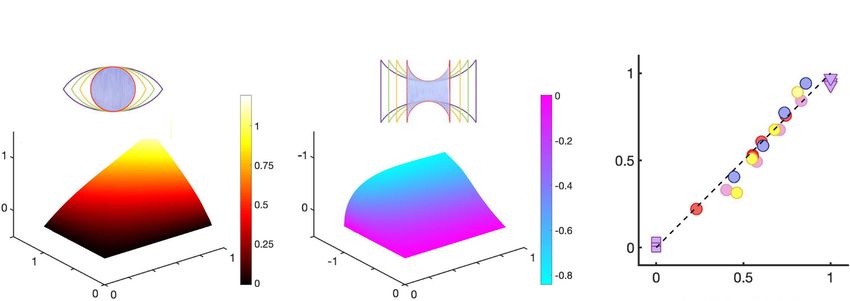
NATURE COMMUNICATIONS | https://doi.org/10.1038/s41467-022-28187-x                                                                      ARTICLE

                             a     stretch           b                  +     c                 −
                                                                                               +−+
                                                                                                        d                  −
                                                                      − +−                                                +−+
                                                                      −+−                      +−+                        −+−
                                                                        +                       −                          −
                            unit               cut

                            boundary
                                                                        +: pop-up
                                    stretch                            −: pop-down
                             e                       f                        g                         o
                                                                         −

                                                                                                             multilayer

                             h                       i                         j

                                                         partially closed          fully closed

                             k                       l                         m                        n

Fig. 4 Combinatorial designs of 2D kirigami precursors for complex 3D shapes under uniaxial tension. a–j Reconfigurable 3D shapes through bistability
of discrete ribbons. a 2D precursor composed of 2 × 2 square units with zero boundary curvature. b–d Uni-axial stretching induced reconfigurable human
face-like morphologies with switchable smiley (b) and sad (c) expressions, as well as eyeglasses (d) by tuning the popping directions of ribbons (insets).
e 2D precursor composed of 3 × 1 rectangle units with zero boundary curvature. f, g Formation of switchable sinusoidal wavy and coiled shapes. h 2D
precursor composed of an array of two circular units bridged with a biconcave unit. i, j Formation of a 3D encapsulated Venus flytrap-like shape through
uniaxial stretching. k–n Formation of a 3D droplet-like shape (l) and vase-like shape (n) by uni-axially stretching 2D precursors with different combined
boundary curvatures (k, m). Insets show the image of a droplet and a vase. o Formation of a flower-like shape by uni-axially stretching multiple layers of
semi-circular 2D precursors. Scale bars = 10 mm.

in Fig. 4f makes it reconfigure into a coiled shape, which could be              makes the combinatorial design easy to handle. To generate the
reversibly switched by flipping back the popping direction.                      water droplet shape, we design a 2D precursor consisting of
   More complex 3D shapes can be generated by combining                         combined a straight line and a circular arc to mimic the 3D
boundary curvatures with different smoothness in stacked 2D                     water droplet’s backbone shape (Fig. 4k). Similarly, the vase-
kirigami precursors (Fig. 4k–n) under uni-axial mechanical                      like shape (Fig. 4n) is generated by stretching two stacked 2D
stretching, e.g., a 3D droplet-like shape (Fig. 4l) and a vase-like             precursors composed of a concave and convex boundary
shape (Fig. 4n). We note that the smoothness of the backbone                    (Fig. 4m). Furthermore, stretching multiple layers of similar
in the generated 3D shapes is controlled by the smoothness of                   semi-circular 2D precursors generates a flower-like shape with
the boundary in their corresponding 2D precursors, which                        multilayer pedals (Fig. 4o).

NATURE COMMUNICATIONS | (2022)13:530 | https://doi.org/10.1038/s41467-022-28187-x | www.nature.com/naturecommunications                                 7
ARTICLE                                                                    NATURE COMMUNICATIONS | https://doi.org/10.1038/s41467-022-28187-x

    a    Inverse design             b                            c                             d                            e

           Using geodesics                               y
             to represent
           the target shape

Fig. 5 Inverse design of 3D shapes. a Flow diagram of the inverse design. b Schematic of using curves to approximate and represent the target shape (side
view of a waterdrop). The inset shows an isometric view. Red, orange, and yellow curves are the boundary curve Γ, geodesic curve G, and backbone curve
B, respectively. c Experimental inverse-design result of the waterdrop shape formed by a 2D kirigami precursor subject to uniaxial tension. The yellow curve
is the backbone in the target shape. d Schematic of using curves to approximate and represent the target shape (side view of a vase), with an isometric
view showing in the inset. e Experimental inverse-design result of the vase shape formed by a 2D precursor subject to uniaxial tension. Scale bars = 10 mm.

Inverse design strategy. Existing methods of inverse design for                 of one representative geodesic curve and one boundary curve in
target 3D-curved shapes using the kirigami approach require                     the target surface. Thus, such a strategy could significantly
complex algorithms to program heterogeneous local deformation                   simplify the calculation (Supplementary Note 5). Moreover,
among networked cut units35,36. Based on the information that                   programming the dynamic shape-shifting morphology of the
discrete ribbons are geodesic curves of the deformed 3D shapes,                 global geometric entity in our design is limited to only one
we propose a straightforward inverse design strategy. It utilizes               variable, i.e., the boundary curvature in terms of Eq. (7). Only
the geodesic curves extracted from the target shapes and the                    geodesic ribbons have zero geodesic curvatures, and their
isometric mapping to prescribe the 2D precursors (Fig. 5a), which               curvatures are the normal curvatures on the morphed surface,
is, in principle, applicable to any target configuration.                        where the easy-to-handle global dynamic program arises
    To illustrate the strategy, we use the target shapes of a water             naturally. It does not require the trivial control and optimiza-
droplet (Fig. 5b) and a vase (Fig. 5d) as two examples for the                  tion of the heterogeneous deformation of the polygons in
inverse design of the 2D kirigami precursors. As shown in Fig. 5b,              networked kirigami structures35,36 or the thickness distribution
d, we first approximate and represent the target shapes by                       of each non-geodesic ribbon in a discretized manner38.
deriving the shape functions of the backbone curve B (highlighted                  Next, based on the revealed design principle on utilizing
in yellow color, see details in Supplementary Note 5), the geodesic             boundary curvature for programmable shape morphing in the
curves G (highlighted in orange color) approximated by elastica                 kirigami sheets, we further explore the potential of harnessing
curves, and the boundary curve Г (highlighted in red color). Next,              dynamic shape morphing for shape-determined multifunction-
based on the isometric mapping from G and Г in the target shape                 ality. To show their potential, we demonstrate two proof-of-
to the 2D precursor, we derive the shape function of the                        concept examples with their potential applications in delicate
prescribed 2D boundary curve ГP (Supplementary Note 5). The                     flexible grippers and conformable heaters.
parametrization of Г and ГP can be expressed in the form of
r Γ ¼ ðxðsb Þ; yðsb Þ; 0Þ and r ΓP ¼ ðxP ðsb Þ; yP ðsb Þ; 0Þ, respectively,     Application: delicate and noninvasive kirigami hand designed
where the superscript P represents the 2D precursor. Accordingly,               via the programmable morphology. A simple, rapid, and eco-
the shape function of the boundary curve ГP in the 2D precursor                 nomical soft gripper is highly required in biomedical robotics and
can be derived as (see details in Supplementary Note 5)                         wildlife-conservation devices. However, for the existing soft
                    P                                                     grippers realized by pneumatic44–46, hydraulic47, and magnetic
                       x ðsb Þ      ηx 0        xðsb Þ
                                 ¼                        ;            ð8Þ      actuation48, and responsive materials17 using pinching44,45,48,
                       yP ðsb Þ     0 ηy        yðsb Þ                          enclosing47, and suction49, it is challenging to balance the
                                                                                response time, manufacturing cost, simplicity of designs, and
where the parameters ηx and ηy are related to the isometric                     robustness in noninvasive grasping missions. Here, utilizing the
mapping. Furthermore, the required strain εre to form the target                dynamically programmable shape morphing, we present a uni-
shape is given by εre ¼ ½xðmaxðsb ÞÞ  xP ðmaxðsb ÞÞ=xP ðmaxðsb ÞÞ             versal, flexible yet robust kirigami hand, which can encapsulate
with max(sb) being the maximum arc length of the boundary                       gelatinous and delicate organisms nondestructively in unstruc-
ribbon.                                                                         tured environments.
   Figure 5c, e show the result of the inverse design of a water                   Subject to simply uniaxial stretch, the 2D kirigami precursor
droplet and a vase after deploying the derived 2D kirigami                      composed of two circular units bridged with a biconcave unit
precursors at an applied strain of εre = 0.14 and 0.07,                         (Figs. 4h and 6a) transforms into an encapsulated Venus-flytrap-
respectively. The inverse design result agrees well with the                    like shape composed of two hemispheres bridged with a saddle
target shape denoted by the yellow curves. We note that for a                   shape (Fig. 6b). To demonstrate its delicacy in noninvasively
target discrete 3D-curved shape, previous studies using the                     grasping extremely soft and slippery objects, we use the example
assembly of disconnected non-geodesic ribbons without an                        of grasping a raw egg yolk from a petri dish with the grasping
enclosed boundary need complicated control and optimization                     process and mechanism from open to closed states shown in
of geometry and distribution of each ribbon locally and globally                Fig. 6c–e in both side view and front view (insets) and
in the inverse design38. Notably, precise control of all the                    Supplementary Movie 3. First, the biconcave unit starts bending
geodesic ribbons and shape optimization are not necessary for                   and forms a V shape with the increasing uniaxial stretch (Fig. 6c).
our proposed inverse design approach, since it harnesses the                    Next, as shown in Fig. 6d, the two circular units transform into
isometric mapping of geodesics and only needs the information                   two hemispheres with the variation of the boundary curvature

8                   NATURE COMMUNICATIONS | (2022)13:530 | https://doi.org/10.1038/s41467-022-28187-x | www.nature.com/naturecommunications
NATURE COMMUNICATIONS | https://doi.org/10.1038/s41467-022-28187-x ARTICLE
a boundary c f g h
stretch stretch
cuts
b stretch d
1.10 live fish in water fish catching shampoo bubble
stretch
i j k
bending raw egg yolk 0.4g
e
1.30
saddle
hemisphere
400g
encapsulating nuts on yolk human hair
Fig. 6 Programmable delicate and noninvasive kirigami gripper. a 2D precursor composed of an array of two circular units bridged with a biconcave unit.
k defines the initial boundary curvature of the units. Yellow arrows are the direction of the uniaxial stretching. Yellow lines and white dashed lines
bo
represent the cuts and the boundaries, respectively. b Isometric view of the morphology from bending to encapsulating upon stretching. Red arrows
represent the morphing direction of the hemisphere. c–e Side views of the grasping process of a raw quail egg yolk with the increasing applied strain from
0.62 to 1.3, respectively. The inset shows the corresponding front views. f, g Encapsulating a live fish from a petri dish filled with water. h Grasping the
super-soft shampoo bubbles from the surface of the water. i Collecting the granular objects (pine nuts) from the super-soft surface of a raw egg yolk.
j, k Grasping a human hair (j) and a deadweight (400 g, k). Scale bars = 10 mm.
and start grasping the egg yolk from the bottom. Last, the
a d Fixed ends flattened boundary curve leads to the closure of the structure and
= 0.5 encapsulating the egg yolk (Fig. 6e), where the super-slippery and
soft yolk can be held for hours showing both the soft yet robust
ability to encapsulate and preserve gelatinous organisms.
Further, to demonstrate the advantage of the bio-interactive
hand, we rapidly encapsulate a live fish from water before it could
pulling out force F F escape (Fig. 6f, g and Supplementary Movie 3); we then release it
0o e unharmed. The noninvasive interaction shows the conformability
and adaptivity of the gripper. Also, encapsulating super-soft
b objects (e.g., shampoo bubbles in Fig. 6h) and the collection of
=1 granular objects (e.g., pine nuts in Fig. 6i) from a super-soft
substrate (e.g., a raw egg yolk) are demonstrated, broadening its
Pulling out force F (N)
versatility and noninvasiveness. Moreover, the universal gripper
can be applied to a wide range of targets, including small objects
such as a human hair (Fig. 6j), a coin, a thin micro-SD card, and
blueberries, etc. (Supplementary Movie 3), as well as a 400 g
145o deadweight (Fig. 6k) that is 1000 times the weight of the gripper
(0.4 g). We note that despite the simple design, the gripper
c kirigami is capable of repeatedly lifting the 400 g deadweight for
=2 over 1400 cycles without causing materials and structural failure
and sacrificing its grasping performance, demonstrating the
robustness of the gripper.
The dynamic morphology programmed via tuning the
boundary curvature can be further harnessed to tailor the holding
force of the flexible gripper47. As shown in Fig. 7a–e, when the
195o Initial boundary curvature normalized initial-boundary curvature kbo (illustrated in Fig. 7a)
of the 2D precursors increases from 0 to 2, after simple stretching,
Fig. 7 Effect of the initial boundary curvature on the pulling-out force of
the angle formed by the two tips of the hemispheres increases
kirigami grippers. a–c Experimental illustration of shapes formed by 2D
from 0 to 195°, correspondingly, their final deformed shapes
precursors with the different initial-boundary curvatures kbo at the maximum transit from open (kbo < 1 in Fig. 7a) to closed (kbo ≥ 1 in Fig. 7b,
applied strain. The insets show the schematic figure of the 2D precursors. The c). The precursor with kbo ¼ 1 defines a critical state, where the
white dashed line represents the angle between the tips of the gripper. two curved ends can become contacted to form a 3D
d Schematic illustration of measuring the pulling-out force F via pulling out a encapsulated shape (Fig. 7b). Correspondingly, as shown in
red sphere from the grippers with various boundary curvatures kbo . Red arrows Fig. 7d, e on the pulling force of the kirigami grippers vs. kbo , it
are the direction of the pulling-out force. e The experimental results on the results in a sudden jump of the pulling-out force of the kirigami
curve of F vs. kbo . The error bars represent the standard errors of the mean. grippers at kbo ¼ 1 from an average force of 0.4 N (kbo < 1) to
NATURE COMMUNICATIONS | (2022)13:530 | https://doi.org/10.1038/s41467-022-28187-x | www.nature.com/naturecommunications 9ARTICLE NATURE COMMUNICATIONS | https://doi.org/10.1038/s41467-022-28187-x
a d e
42
Ag nanowire
M
22
PDMS cuts
b c f 0.02 38.5
Temperature ( )
iii
geodesics
knee
ΔR/R
0.01
38
0
glue point 37.5
heater 0 15 30 45 60 75 90
boundary
shrimp curling Bending angle (o)
Fig. 8 Dynamically conformable biomimetic heater. a Photograph of the 2D precursor. Scale bar: 10 mm. The right shows the schematics of the cross-
section of the AgNW/PDMS heater and the cut pattern. b, c Schematics of the heater mimicking the shell of the Mantis shrimp composed of geodesics
attached to the human knee. b Curling shell of the Mantis shrimp. Yellow lines represent geodesics. c Schematic of the heater attached to the knee. Pink
and yellow lines are the boundary and the geodesics, respectively. Red dots are the points with the adhesive. Black dashed lines representing the geodesics
are perpendicular to the boundary with the knee bending. d, e The kirigami heater deforms with the knee as the knee bends from 0° (d) to 90° (e) and the
corresponding thermal image upon heating. φ denotes the bending angle of the knee. M is the center of the knee. The color bar represents the temperature.
f Electric resistance of the heater and the temperature of the point M as a function of the bending angle φ.
6.1 N (kbo ≥ 1), a 15 times grasping force enhancement. The curvature and the 3D morphology and demonstrate an electrically
pulling force is defined as the minimum force required to pull the driven resistive human-knee heater mimicking the conformability
red sphere out of the gripper, as schematically illustrated in of the Mantis shrimp’s shell. It shows intrinsic adaptivity with
Fig. 7d. The force jump is because the grasping mode transits decent conformability and large-area uniform-heating capability.
from pinching by friction to distinct encapsulating due to the As shown in Fig. 8a, the heater is composed of silver nanowires
programmed shape of the grippers by the boundary curvature. (AgNWs)54,55 and the PDMS (polydimethylsiloxane) kirigami
Further increasing the normalized boundary curvature beyond sheet with parallel cuts. It generates Joule heating with a constant
2 does not lead to a higher pulling force (Supplementary direct current applied (see “Methods” section). Mimicking the
Fig. 12b), since all the grippers share a similar closed shape curling shell of the Mantis shrimp (Fig. 8b), the heater includes
under the same encapsulating grasping mode (Supplementary discrete ribbons that are consistent with the geodesics of the knee,
Fig. 12a), where further deformation is constrained by the which are normal to the boundary. Four vertices of the kirigami
contacted hemisphere petals. Furthermore, for the kirigami AgNW-PDMS pad are bonded to the knee, as shown in Fig. 8c.
grippers with the same size and geometry, when reducing the As the knee bends from 0 to 90°, the discrete ribbons deform
number of parallel cuts or equivalently increasing the ribbon induced by the variation of the boundary curvature like the
width (Supplementary Fig. 13a–e), we observe the similar sudden curling of the shell of the shrimp (Fig. 8d, e). The geodesic
jumping of the dramatically reduced pulling force at a critical feature, same as the shell, endows intrinsic adaptivity, and the
ribbon width 0.875 mm (Supplementary Fig. 13f and Supple- heater shows decent conformability and uniform-heating cap-
mentary note 6), arising from the same grasping transition mode ability, where the standard deviation of the temperature across
from encapsulating to pinching (Supplementary Fig. 13a–e). the knee before and after bending is 0.73 °C and 0.97 °C,
It is noteworthy that using pinching or the friction force, respectively (Fig. 8d, e). With the increase of the bending angle
existing kirigami grippers are not well suited for grasping φ, the temperature at the center of the heater (point M in Fig. 8d)
gelatinous organisms17,48. These grippers need to compress or slightly decreases, resulting from the small increase in the
pinch the targets to lift the targets, making the noninvasive resistance of AgNWs (~1%), which shows stable heating
collection of the delicate organisms challenging17,48. Distinct capability (Fig. 8f). We note that the cyclic heating and cooling
from that, we demonstrated a grasping mode, encapsulating the do not degrade the performance of the device, where the
targets ultra-gently without compressing the objects, via the resistance-temperature curves barely change after 100 cycles of
programmable dynamic morphology, which is especially suitable heating and cooling from 25 to 42 °C (Supplementary Fig. 14).
for grasping delicate organisms nondestructively. Also, the The discrete ribbon-based kirigami design offers the unique
pulling-out force of our gripper could be an order of magnitude features of adaptivity, conformability, and flexibility combined
(about ten times) larger than recently reported kirigami with a large contact area, which can be potentially applied to
grippers48 at the same scale by harnessing the dynamically wearable sensors, flexible electronics, and textile electronics.
programmed morphology.
Discussion
Application: conformable heater composed of the geodesic We proposed a new way of utilizing the cut boundary curvature
ribbons. Conformable heating devices are desired for human to guide the formation of controllable and reconfigurable com-
joints to relieve pain50. The inhomogeneous deformation and plex 3D-curved shapes in kirigami sheets patterned with simple
complex-curved shapes51 of the joints, such as the human knee, parallel cuts. Such a strategy is validated through combined
result in the trade-off between the large contact area (between the theoretical modeling, FEM simulations, and experiments. The
device and the human skin) and the conformability and adap- unique feature of discrete cut ribbons as geodesic curves of the
tivity, especially during motion. Here, different from existing deformed 3D shapes largely simplifies the inverse design. Pro-
heaters32,52,53, we harness the correlation between the boundary gramming the dynamic 3D morphology, we showed a universal
10 NATURE COMMUNICATIONS | (2022)13:530 | https://doi.org/10.1038/s41467-022-28187-x | www.nature.com/naturecommunicationsNATURE COMMUNICATIONS | https://doi.org/10.1038/s41467-022-28187-x ARTICLE
noninvasive flexible kirigami gripper for grasping and preserving Methods
delicate organisms and a biomimetic kirigami heater with decent Simplification of the Gauss–Bonnet theorem. The Gauss–Bonnet theorem can be
conformability and intrinsic adaptivity to human knees. simplified according to the constant Euler characteristic and summation of the
exterior angles. The Euler characteristic of the surface is a topological invariant and
The parallel cuts ensure easy fabrication. However, there are keeps a constant during deformation. For the surface formed by two neighboring
some limitations on our proposed method in terms of the discrete ribbons, as shown in Supplementary Fig. 1, the Euler characteristic is
achievable morphed shapes and the level of curvature given by
programmability56. It is challenging for the straight discrete χ ðΩÞ ¼ V E þ F ¼ 1; ð9Þ
ribbons to approximate an axisymmetric shape perfectly due to
where V, E, and F denote the numbers of vertices, edges, and faces of the manifold
the limitation of their elastica shape (e.g., a cone shape). The Ω, respectively. In this process, V, E, and F do not change with the increasing strain
inverse design with a high-accuracy requirement will need local (Supplementary Fig. 1c, f, i), resulting in a constant Euler characteristic.
optimization of the boundary curve. For targeted more complex The summation of the exterior angles does not change under tension and the
3D surface shapes with arbitrary negative and positive curva- variation in summation is expressed as
P ( " !# )
tures, the inverse design will become more challenging since it wd
needs to utilize the smoothness of two orthogonal geodesics to Δ ∑ θi ¼ 2 4 α2s sb þ 4 α2s sb ¼ 0; ð10Þ
i¼1 sin α2s
design both the tessellation of different shaped unit cells and the
shapes of inner and outer boundary curves. Moreover, com- where Δð∑Pi¼1 θi Þ denotes the variation of the summation of the exterior angles;
pared to the intrinsic deployment of retained 3D shapes through α2s sb denotes the angle between the tangent line of the boundary ribbon and the
discrete ribbon at the point of intersection and is a function of the arc length of the
bistability56 or pre-strain release16 after force removal, our boundary ribbon sb; the coefficient 2 is from the symmetry of the structure; wd is
approach requires the application of external stretching forces to the width of the discrete ribbons. Note that we assume the distance 4sb between
remain the deployed shapes, otherwise, the generated 3D shape two discrete ribbons along the boundary ribbon is expressed as 4sb ¼ sinwαd
ð 2s Þ
will return to its original flat form after the external actuation is because wd R, with R being the half-width of the 2D precursor.
removed due to the fully reversible elastic deformation in the For the cylindrical and spheroidal shape, it is obvious that 4α2s ¼ 0 during the
thermoplastic kirigami structure. To preserve the deformed 3D deformation due to the conformal mapping (Supplementary Fig. 1). For the saddle
shape, while α2s is changing due to the contact between the discrete ribbons, and
shapes, we could utilize the shape memory properties of the PET the summation of the exterior angles keeps constant because the variation of the
polymer upon heating above its glass transition temperature57. angles of two neighboring discrete ribbons has the same absolute value. It is
We use thermal treatment under 120 °C to treat the 3D shapes noteworthy that the Gauss–Bonnet theorem is first applied to the surface formed
held at an applied stretching strain for a period of 120 min and by two neighboring discrete ribbons and then extended to the entire structure.
cooled down to the room temperature to fix the deformed
configuration (Supplementary Fig. 15b). Notably, the preserved Variation of the geodesic curvature. The curve of the ribbon is parametrized by
3D configuration can be further deformed and recover to its 2D arc length as shown in Supplementary Fig. 2a, c, e; the origin is located at the
midpoint of each ribbon; sb and sd denote the arc length coordinate of the
flat precursor shape upon another thermal treatment (Supple- boundary and discrete ribbons, respectively. The integral of geodesic curvature
mentary Fig. 15c). along the smooth boundaryR of the
R manifoldR(Supplementary Fig. 1c, f, i) is com-
Despite the demonstration of programmable shaft shifting in posed of two parts, i.e., kg ds ¼ kgd dsd þ kgb dsb , where kgd and kgb denote the
the thermoplastic kirigami sheets, we envision that the proposed geodesic curvature along the discrete and boundary ribbons, respectively. The
strategy is material and scale independent. We note that despite geodesic curvature of the discrete ribbons is equal to zero (kgd ¼ 0), because the
discrete ribbons are geodesics of the morphed surface (normal vectors of discrete
the large applied stretching strain ε, the maximum principal ribbons are normal to the tangent plane). As such, the integral is simplified as
strain εmax in the buckled ribbons with thickness of 127 μm Z Z
remains small (εmax < 1% for ε > 50%, Supplementary Fig. 16 and kg ds ¼ kgb ds; ð11Þ
Supplementary Note 7), e.g., εmax = 0.4% in the deformed sphe-
rical shape at ε = 30% (Fig. 2d) and εmax = 0.6% in the saddle where ds denotes the line element along the boundary of the manifold formed by
two neighboring discrete ribbons.
shape at ε = 147% (Fig. 2h). Note that at the tip of the cuts, the Further, the geodesic curvature of the boundary ribbons is equal to the
stress concentration could be reduced via curved cuts, and projection of the curvature of the boundary ribbon on the tangent plane Tp of the
moderate plastic deformation could be tolerated, as demonstrated surface, as shown in Supplementary Fig. 3. According to the Meusnier theorem37,
by the over 1400 repeated cycles of 400 g deadweight lifting with the relationship between the curvature of the boundary ribbon and the geodesic
curvature is given by
the gripper without failure. Considering the small peak tensile
strain in the buckled ribbons and its linear relationship with sheet kgb ¼ < r00b ; S > ¼ kb sinφ; ð12Þ
thickness t, i.e., εmax decreases linearly with t, we envision that the where kb is the curvature along the boundary ribbon. kgb is the geodesic curvature
proposed kirigami strategy could also be applied to design shape- along the boundary ribbon. Vector rb denotes the boundary curve parameterized
morphing and stretchable structures and devices made of other by arc length and r00b = kb . The angle φ (Supplementary Fig. 3) is given in Eq. (2)
functional materials such as metals and even semiconductors at of Supplementary note 1.
small scales, as well as other stimuli-responsive materials actuated
by temperature, electrical, and magnetic field, etc. Fabrication, mechanical testing, and thermal treatment of the kirigami sheets.
Besides the simple parallel cut pattern, we further explored We used polyethylene terephthalate (PET) sheets (Dupont Teijin Film,
McMaster–Carr) with Young’s modulus of 3.5 GPa, Poisson’s ratio of 0.38, and
applying the strategy of boundary curvature guided shape thickness of 0.127 mm for the kirigami sheets. The samples with different cut
morphing in kirigami sheets to other homogeneous cut pattern- patterns were cut out using a laser cutter (EPILOG LASER 40 W) with cut ribbon
ing, such as the triangular cut pattern. As demonstrated by the width of 1.5 mm in Fig. 1a, b and 0.75 mm in Fig. 1c. Uniaxial tensile tests were
proof-of-concept experiment in Supplementary Fig. 17, it shows performed using Instron 5944 to characterize the force–displacement curves under
a loading rate of 10 mm/min. Thermal treatment (120 °C for 120 min) of the
the formation of approximately similar curved surfaces as the deformed PET samples under a stretched state in an oven fixed the generated 3D
parallel cuts by manipulating different boundary curvatures of the shapes upon cooling to room temperature and force removal. To recover to the
2D precursors, but arising from distinct both local and global out- initial flat state, a second thermal treatment of the deployed 3D shapes was con-
of-plane buckling in the cut units (Supplementary Note 8). The ducted under 120 °C for 120 min in the oven.
detailed deformation mechanism and its potential generality to
other cut patterns will be explored and examined in the future. Finite element simulation. In the FEM simulation (Abaqus/Standard), the PET
sheets corresponding to three different morphologies as a spheroid, cylinder, and
This work could find potential applications in designing soft saddle were modeled as linear elastic, isotropic material with the measured Young’s
robots, non-invasive soft grippers, stretchable electronics, wear- modulus of 3.5 GPa and Poisson’s ratio of 0.38. The geometries were meshed with
able devices, and portable, and wearable heaters. solid quadratic tetrahedral elements (C3D10H) and the fine mesh was applied to
NATURE COMMUNICATIONS | (2022)13:530 | https://doi.org/10.1038/s41467-022-28187-x | www.nature.com/naturecommunications 11You can also read