Body and Equipment Mounting Manual - FORD Ranger 2019 - E289759 - Ford Australia
←
→
Page content transcription
If your browser does not render page correctly, please read the page content below

FORD Ranger 2019
            Body and Equipment Mounting Manual

    E289759

Date of Publication: 07/2018
The information contained in this publication was correct at the time of going to print. In the interest of development the right is reserved to change
specifications, design or equipment at any time without notice and without incurring any obligations. This publication, or part thereof, may not be
reproduced nor translated without our approval. Errors and omissions excepted.

© Ford Motor Company 2018

All rights reserved.

Table of Contents
                                                                                               1.14.1      Towing Requirements..............................30
1 General Information                                                                          1.14.2      Towing...........................................................30
                                                                                               1.14.3      Towing capacities.....................................30
1.1      About this Manual...............................5                                     1.14.4      Trailer Towball Download........................31
  1.1.1     New for this BEMM publication                                                      1.14.5      Towing Specifications...............................31
            07/2018............................................................5
  1.1.2     Introduction....................................................5
  1.1.3     Important Safety Instructions.................5
  1.1.4     Warnings, Cautions and Notes in This                                             2 Chassis
            Manual.............................................................5
  1.1.5     How to Use This Manual...........................5
  1.1.6     Low Level and High Level                                                         2.1 Suspension System...........................32
            Vehicles............................................................6            2.2 Brake System.....................................33
1.2 Commercial and Legal Aspects..........7                                                    2.2.1 General..........................................................33
  1.2.1     Terminology....................................................7                   2.2.2 Brake Hoses.................................................33
  1.2.2     Warranty on Ford Vehicles........................7                                 2.2.3 Trailer Brakes ..............................................33
  1.2.3     Legal and Vehicle Type Approval...........7
  1.2.4     Alternative Type Approval.........................7
  1.2.5     Legal Obligations and Liabilities.............7
  1.2.6 General Product Safety                                                               3 Powertrain
            Requirement...................................................7
  1.2.7     Product Liability............................................8
  1.2.8 Restraints System........................................8                           3.1 Fuel System.......................................35
  1.2.9     Drilling and Welding....................................8                          3.1.1 Fuel Filler Pipe Shipping Bracket (if
  1.2.10 Minimum Requirements for Brake                                                              equipped).....................................................35
            system and Load Apportioning Valves                                                3.1.2 Fuel Filler Mounting...................................37
            .............................................................................8     3.1.3 Fuel Filler Vent Hose................................39
  1.2.11 Road Safety....................................................8                      3.1.4 Axle Breather Vent Hose........................40
1.3 Conversion Homologation..................9
1.4 Electromagnetic Compatibility
         (EMC).................................................10
  1.4.1     Electromagnetic Compatibility.............10                                     4 Electrical
1.5 Vehicle Duty Cycle Guidelines...........12
  1.5.1     Conversion Effect on Fuel Economy
            and Performance........................................12                        4.1 Battery and Cables.............................41
  1.5.2     Vehicle Ride and Handling                                                         4.1.1   Battery Information...................................41
            Attributes.......................................................12               4.1.2   Generator and Alternator........................47
1.6 Jacking................................................13                                4.2 Electronic Engine Controls...............48
1.7      Lifting.................................................14                           4.2.1   Vehicle Speed Output (Signal) (Low
1.8 Noise, Vibration and Harshness                                                                    Level Vehicles Only).................................48
         (NVH).................................................15                             4.2.2 Vehicle Speed Output (Signal) (High
1.9 Vehicle Transportation Aids and                                                                   Level Vehicles )...........................................54
         Vehicle Storage..................................16                                 4.3 Exterior Lighting................................55
1.10 Package and Ergonomics...................17                                              4.3.1   Rear Combination lamps.......................56
  1.10.1 General Component Package                                                            4.3.2 Rear Fog Lamp...........................................56
            Guidelines......................................................17                4.3.3 Rear License Plate Lamp........................57
  1.10.2 Driver Reach Zones.....................................17                            4.3.4 Reversing Lamps, Rear View Camera,
  1.10.3 Driver Field of View.....................................17                                  Reversing Alarm (Manual
  1.10.4 Conversion Effects on Parking                                                                Transmission).............................................59
            Aids...................................................................17         4.3.5 Additional External Lamps - (Low
  1.10.5 Aids for Vehicle Entry and Exit...............17                                             Level Vehicles Only).................................59
  1.10.6 Registration Plates.....................................18                           4.3.6 Trailer Towing.............................................60
1.11 Package and                                                                              4.3.7 Auxiliary Lighting Loads (Low Level
         Ergonomics—Specifications.............19                                                     Vehicles Only).............................................62
  1.11.1    Recommended Body Dimensions.......19                                              4.3.8 Lamps – Hazard / Direction
  1.11.2 Chassis Cab Body - Basic Dimensions                                                          Indication......................................................63
            and Weights................................................20                     4.3.9 Electrically Operated Door
  1.11.3 Kerb Mass and Payload............................21                                          Mirrors............................................................63
  1.11.4 Front, Rear and Side Under-run                                                       4.3.10 Centre High Mount Stop Lamp
            Protection......................................................21                        (CHMSL) - Canopy Fitment -Low
1.12 Hardware—Specifications................22                                                        Level Vehicles..............................................63
1.13 Load                                                                                     4.3.11 Centre High Mount Stop Lamp
         Distribution—Specifications............23                                                    (CHMSL) - Canopy Fitment - High
  1.13.1 Load Distribution Calculations - Driver                                                      Level Vehicles.............................................64
            and Passenger Weight                                                             4.4 Handles, Locks, Latches and Entry
            Distribution...................................................23                       Systems.............................................66
  1.13.2 Center of Gravity........................................26                          4.4.1   Central Locking..........................................66
1.14 Towing...............................................30                                 4.5 Fuses and Relays...............................67

                                                                                                                                                                                       3
Table of Contents     4.5.1       Low Level and High Level Vehicles.......67
                      4.5.2       Auxiliary Battery and Fuse Box - Low
                                  Level Vehicles...............................................67
                      4.5.3       Auxiliary Fuse Box (Vehicles with
                                  Special Equipment Pack) (Low Level
                                  Vehicles Only)..............................................68

                    5 Body and Paint
                    5.1 Body.....................................................71
                      5.1.1   Body Structures - General
                              Information.....................................................71
                      5.1.2   Integrated Bodies and
                              Conversions....................................................71
                      5.1.3   Chassis Cab...................................................72
                      5.1.4   Front End Integrity for Cooling, Crash,
                              Aerodynamics and Lighting....................75
                      5.1.5   Tipper Bodies................................................75
                      5.1.6 Tank and Dry Bulk Carriers......................76
                      5.1.7   Genuine Ford Accessory Bull Bar..........76
                      5.1.8 Roof Racks.....................................................77
                      5.1.9 Canopies........................................................78
                    5.2 Airbag Supplemental Restraint
                            System (SRS).....................................81
                      5.2.1   Air Bags - (Low Level Vehicles)..............81
                      5.2.2 Air Bags - (High Level Vehicles)............84
                      5.2.3 Supplementary Restraint Sensors
                              (Front).............................................................87
                    5.3 Seatbelt Systems – Australia...........89
                    5.4 Corrosion Prevention.........................90
                      5.4.1   General...........................................................90
                      5.4.2 Repairing Damaged Paint.......................90
                      5.4.3 Under Body Protection and
                              Material..........................................................90
                      5.4.4 Painting Road Wheels..............................90
                      5.4.5 Contact Corrosion......................................90
                    5.5 Frame and Body Mounting.................91
                      5.5.1   Mounting Points and Tubing...................91
                      5.5.2 Self-Supporting Body Structure...........92
                      5.5.3 Frame Drilling and Tube
                              Reinforcing....................................................93
                      5.5.4 Ancillary Equipment - Sub Frame
                              Mounting........................................................93
                      5.5.5 Area for Fitting Additional Body
                              Attachments to the Rear of the
                              Bumper. .........................................................93
                      5.5.6 Water Tank on Camper Vehicles...........93

   4
1 General Information
       1.1 About this Manual
       1.1.1 New for this BEMM publication                     Ford cannot guarantee the operation of the
       07/2018                                                 vehicle if non-Ford approved electrical systems
                                                               are installed. Ford electrical systems are designed
       It is recommended to review this manual in full.        and tested to function under operational
       The BEMM is a live document which can be viewed         extremes, and have been subjected to the
       on www.etis.ford.com/BEMM or                            equivalent of ten years of driving under such
       http://www.fordtechservice.dealerconnection.com/.       conditions.
       It is the vehicle converters responsibility to review
       the online version for the most current information
       prior to starting any conversion. For an overview       1.1.3 Important Safety Instructions
       of the main differences please see below.
                                                               Appropriate conversion procedures are essential
       The following sections of the manual have been          for the safe, reliable operation of all vehicles as
       updated to support the Model Year 19 Ranger             well as the personal safety of the individual
       MCA:                                                    carrying out the work.
       •   Trailer Brake Controller implementation.            This manual cannot possibly anticipate all such
           Refer to: 2.2 Brake System (page 33).               variations and provide advice or cautions as to
                                                               each. Anyone who departs from the instructions
       •   Battery Specifications.
                                                               provided in this manual must first establish that
           Refer to: 4.1 Battery and Cables (page 41).         they compromise neither their personal safety nor
       •   Electromagnetic Compatibility (EMC)                 the vehicle integrity by their choice of methods,
           Specifications.                                     tools or components.
           Refer to: 1.4 Electromagnetic Compatibility
            (EMC) (page 10).                                   1.1.4 Warnings, Cautions and Notes in
       •   Towing Specifications.                              This Manual
           Refer to: Towing (page ?).                               WARNING: Warnings are used to indicate
       •                                                            that failure to follow a procedure
                                                                    correctly may result in serious injury or
                                                                    death.
       1.1.2 Introduction
                                                                    CAUTION: Cautions are used to indicate
       NOTE: Printed copies are uncontrolled.                       that failure to follow a procedure
                                                                    correctly may result in damage to the
       This manual has been written in a format that is             vehicle or equipment being used.
       designed to meet the needs of Vehicle Converters.
       The objective is to use common formats with the         NOTE: Notes are used to provide additional
       workshop manual which is used by technicians            essential information required to carry out a
       worldwide.                                              complete and satisfactory repair.
       This guide is published by Ford and provides            As you read through this manual, you will come
       general descriptions and advice for converting          across WARNINGS, CAUTIONS and NOTES.
       vehicles. These requirements must be complied           A warning, caution or note is placed at the
       with before a Ford Dealer should take delivery of       beginning of a series of steps if it applies to
       motor vehicle accessories from an external              multiple steps. If the warning, caution or note only
       supplier either for themselves or on behalf of a        applies to one step, it is placed at the beginning
       motor vehicle client.                                   of the specific step (after the step number).
       It must be emphasized that any change to the
       basic vehicle which does not meet the enclosed
       guideline standards may severely inhibit the ability
                                                               1.1.5 How to Use This Manual
       of the vehicle to perform its function. Mechanical
                                                               This manual covers vehicle conversion procedures.
       failures, structure failure, component unreliability
       or vehicle instability will lead to customer            The pages at the start of this manual list the
       dissatisfaction. Appropriate design and                 content, by group. A group covers a specific
       application of body, equipment and or accessories       portion of the vehicle. The manual is divided into
       is key to ensuring that customer satisfaction is        four groups, General Information, Chassis,
       not adversely affected.                                 Electrical, Body and Paint. The number of the
                                                               group is the first number of a section number.
       The information contained within this publication
                                                               Each title listed in the contents links to the
       takes the form of recommendations to be
                                                               relevant section of the manual.
       followed when vehicle modifications are
       undertaken. It must be remembered that certain          In some section of the book it may refer you to
       modifications may invalidate legal approvals and        see additional sections for information, links have
       application for re-certification may be necessary.      been provided, these links are in blue text.

FAPA   FORD RANGER 2019 2019                                                                Date of Publication: 07/2018          5
1 General Information   This manual is designed to be used online or as
                        printed material, document links for the online
                        version are also shown with page numbers for the
                        printed version, this will help guide you to the start
                        of the section which contains the relevant
                        information.
                        There is also an alphabetical index at the back of
                        the manual. As with the contents pages you will
                        be able to link to sections. To do this just click on
                        the page number.
                        All left and right-handed references to the vehicle
                        are taken from a position sitting in the driver seat
                        looking forward unless otherwise stated.

                        1.1.6 Low Level and High Level Vehicles
                              WARNING: Prior to work on any vehicle
                              being undertaken it is critical to identify
                              the type of electrical architecture the
                              vehicle at hand is equipped with. Failure
                              to identify the type of electrical
                              architecture present on the vehicle prior
                              to work being undertaken may cause
                              electrical damage or have safety
                              implications.
                        Ford Ranger PX MkII vehicles are equipped with
                        one of two electrical architectures.
                        Refer to: 4.5 Fuses and Relays (page 67).

   6                    Date of Publication: 07/2018                             FORD RANGER 2019 2019   FAPA
1 General Information
       1.2 Commercial and Legal Aspects
       1.2.1 Terminology
                                                                1.2.4 Alternative Type Approval
       NOTE: Any modifications to the vehicle must be
       noted in the owner's handbook or new descriptive         If significant changes are made the Body Builder
       literature included with the owner's                     must negotiate with the relevant authority. Any
       documentation.                                           changes to the vehicle operating conditions must
       Vehicle Converter refers to any re-seller altering       be advised to the customer.
       the vehicle by converting the body and adding or
       modifying any equipment not originally specified         1.2.5 Legal Obligations and Liabilities
       and or supplied by Ford.
       Unique component or similar wording refers to            The Vehicle Converter should consult with its legal
       non-Ford specified or after sale fitment not             advisor on any questions concerning its legal
       covered by Ford warranty.                                obligations and liabilities.
                                                                Ford recommends that the Vehicle Converter and
       1.2.2 Warranty on Ford Vehicles                          Ford Dealer must understand their individual and
                                                                joint responsibilities in supplying a safe and
       Please contact The National Sales Company in             compliant motor vehicle fitted with safe and
       the country where the vehicle will be registered         compliant accessories.
       or refer to the vehicle Owner Guide for details of
       the terms of any applicable Ford warranty.               1.2.6 General Product Safety
       The Vehicle Converter should warrant its design,         Requirement
       materials and construction for a period at least
       equal to any applicable Ford warranty.                   The Vehicle Converter shall ensure that any
                                                                vehicle it places on the market complies with all
       The Vehicle Converter must ensure that any               local laws, including laws relating to the safe
       alteration made to a Ford vehicle or component           carriage of loads on public roads. The Vehicle
       does not reduce the safety, function, or durability      Converter shall also ensure that any alteration it
       of the vehicle or any component.                         makes to a Ford vehicle or component does not
       The Vehicle Converter shall be solely responsible        reduce its compliance with local design rules.
       for any damage resulting from any alteration             The Vehicle Converter must provide sufficient
       made by the Vehicle Converter or any of its agents       Load Restraint tie down points or
       to a Ford Vehicle Component.                             compartmentalised storage areas that enable
       The Vehicle Converter releases Ford from all             the driver to safely carry loads that match the use
       claims by any third party for any cost or loss           criteria for which the body was designed.
       (including any consequential damages) arising            The Vehicle Converter shall release Ford from all
       from work performed by a Vehicle Converter               liability for damages resulting from:
       unless Ford has given its prior written consent to
       such liability.                                          •   Failure to comply with these Body Equipment
                                                                    Mounting directives, in particular warnings.

       1.2.3 Legal and Vehicle Type Approval                    •   Faulty design, production, installation,
                                                                    assembly or alteration not originally specified
       •   All components embodied on Ford vehicles are             by Ford.
           approved to the applicable legal requirements.       •   Failure to comply with the basic fit for purpose
       •   Ford vehicles have Type Approval for the                 principles inherent in the original product.
           intended marketing territories.
                                                                WARNINGS:
             WARNING: Exception - Incomplete
                                                                     Do not exceed the gross vehicle mass,
             vehicles require further approval when
                                                                     gross combination mass, axle ratings and
             completed by the Body Builder.
                                                                     trailer rating.
       •   The Ranger range has Type Approval for many
           territories, although the full range of vehicles          Do not change the tire size or load rating.
           shown in this manual are not necessarily
           released in all territories. Check with your local        Do not modify the steering system.
           Ford National Sales Company representative.
       •   Significant changes to the vehicle may affect             Excessive heat can build up from the
           its legal compliance. Strict adherence to the             exhaust system, in particular from the
           original design intent for brakes, weight                 catalytic converter and from the Diesel
           distribution, lighting, electrical systems,               Particulate Filter (DPF). Ensure adequate
           occupant safety and hazardous materials                   heat shields are maintained. Maintain
           compliance in particular is mandatory.                    sufficient clearance to hot parts.

FAPA   FORD RANGER 2019 2019                                                                 Date of Publication: 07/2018           7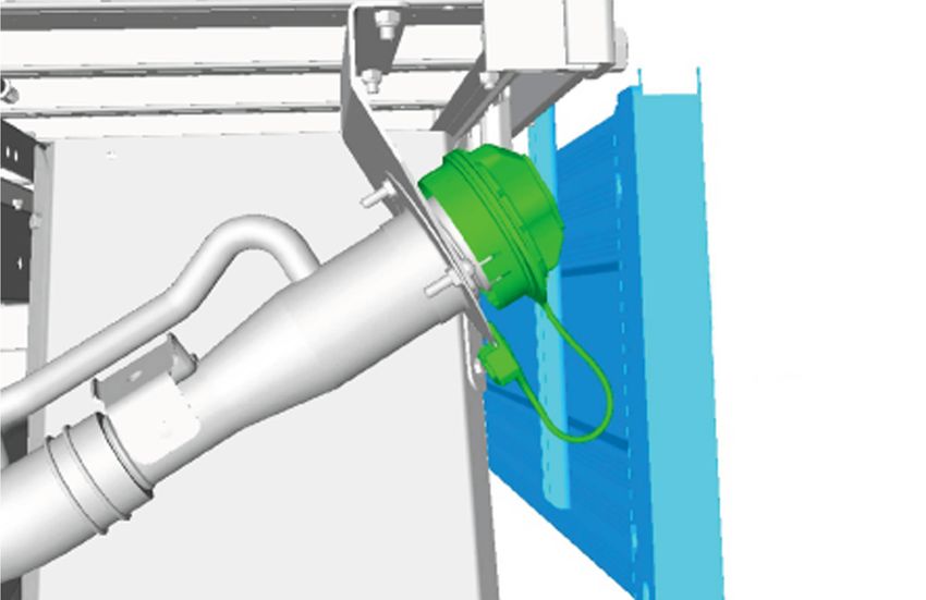
1 General Information         Do not modify or remove heat protection                 Do not alter, modify or relocate the airbag,
                              shields.                                                sensor and modules of the restraints
                                                                                      system or any of its components.
                              Do not route any electrical cables with the
                              Anti-lock Brakes System and Traction                    Attachments or modifications to the front
                              Control System cables because of                        end of the vehicle may affect the airbag
                              extraneous signal risk. Do not hang                     fire timing and result in uncontrolled
                              electrical cables off existing looms or                 deployment.
                              pipes.
                                                                                      Modifications to the B-Pillar body
                              Do not change original location or remove               structure may affect the side airbag fire
                              warning labels provided with the base                   timing and result in uncontrolled side
                              vehicle in view to the driver. Ensure that              airbag deployment.
                              labels in view to the driver in the base           Refer to: 5.2 Airbag Supplemental Restraint
                              vehicle remain in full view to the driver           System (SRS) (page 81).
                              after any conversion.
                        NOTE: For further information please contact your
                        local National Sales Company representative, or          1.2.9 Drilling and Welding
                        Local Ford Dealer.
                                                                                 Drilling and welding of frames and body structures
                                                                                 have to be conducted following the guidelines
                        1.2.7 Product Liability                                  within this document.

                        The Vehicle Converter shall be liable for any
                        product liability (whether for death, personal injury,   1.2.10 Minimum Requirements for
                        or property damage) arising from any alteration          Brake system and Load Apportioning
                        to a Ford vehicle or component made by the               Valves
                        Vehicle Converter or any of its agents. Ford shall
                        not be liable for any such liability (except as          •   It is not necessary or recommended to modify
                        provided by law).                                            the load apportioning valves, however, if a
                                                                                     special conversion should require modifications,
                        The Vehicle Converter or equipment manufacturer              – Maintain original settings.
                        is liable for the:
                                                                                     – Maintain brake certification load distribution.
                        •   Operational reliability and road-worthiness of
                            the vehicle to its original intent.                  •   Changes to the Antilock Brake System (ABS),
                                                                                     Traction Control System (TCS) and Electronic
                        •   Operational reliability and road-worthiness of           Stability Program (ESP) system are not
                            any component or conversion, not listed in               permitted.
                            original Ford documentation.
                        •   Operational reliability and road-worthiness of       1.2.11 Road Safety
                            the vehicle as a whole (for example the body
                            changes and/or additional equipment must not         The respective instructions should be strictly
                            have a negative effect on the driving, braking       observed to maintain operational and road safety
                            or steering characteristics of the vehicle).         of the vehicle.
                        •   Any damage resulting from the conversion or
                            attachment and installation of unique
                            components, including unique electrical or
                            electronic systems.
                        •   Functional safety and freedom of movement
                            of all moving parts (for example axles, springs,
                            propeller shafts, steering mechanisms, brake
                            and transmission linkage).
                        •   Functional safety and freedom of the tested
                            and approved flexibility of the body and integral
                            chassis structure.

                        1.2.8 Restraints System
                        WARNINGS:
                              Modifications to the restraints system
                              are not allowed.
                              Airbags are explosive. For safe removal
                              and storage during conversion follow the
                              procedures in the Ford workshop manual
                              or consult your local National Sales
                              Company representative.

   8                    Date of Publication: 07/2018                                                      FORD RANGER 2019 2019          FAPA
1 General Information
       1.3 Conversion Homologation
       The Vehicle Converter must observe any statutory
       rules and regulations. When the conversion needs
       a new approval the following information must
       be quoted.
       •   All dimensional, weight and centre of gravity
           data.
       •   The fixing of the body to the donor vehicle.
       •   Operating conditions.
       The responsible Technical Service may require
       additional information and/or testing.
       NOTE: For further information please contact
       your local National Sales Company representative,
       or Local Ford Dealer.

FAPA   FORD RANGER 2019 2019                               Date of Publication: 07/2018         9
1 General Information   1.4 Electromagnetic Compatibility (EMC)
                        1.4.1 Electromagnetic Compatibility                      Keep antenna and power cables at least
                                                                                 100mm from any electronic modules and
                        WARNINGS:                                                airbags.
                              Do not place objects or mount equipment       NOTE: We test and certify your vehicle to meet
                              on or near the airbag cover, on the side of   electromagnetic compatibility legislation (UNECE
                              the seatbacks (of the front seats), or in     Regulation 10 or other applicable local
                              front seat areas that may come into           requirements). It is your responsibility to make sure
                              contact with a deploying airbag. Failure      that any equipment an authorized dealer installs
                              to follow these instructions may increase     on your vehicle complies with applicable local
                              the risk of personal injury in the event of   legislation and other requirements.
                              a crash.
                                                                            NOTE: Any radio frequency transmitter equipment
                              Do not fasten antenna cables to original      in your vehicle (such as cellular telephones and
                              vehicle wiring, fuel pipes and brake pipes.   amateur radio transmitters) must keep to the
                                                                            parameters in the following table. We do not
                                                                            provide special provisions or conditions for
                                                                            installations or use.

                             E239120

                                             E239122

10                      Date of Publication: 07/2018                                                FORD RANGER 2019 2019           FAPA
1 General Information
E239121
Frequency Band MHz Maximum Output Power Antenna Position
Watts (Peak RMS)
1-30 50 1
50-54 50 2, 3
68-88 50 2, 3
142-176 50 2, 3
380-512 50 2, 3
806-870 10 2, 3
NOTE: After the installation of radio frequency
transmitters, check for disturbances from and to
all electrical equipment in your vehicle, both in
the standby and transmit modes.
Check all electrical equipment:
• with the ignition ON
• with the engine running
• during a road test at various speeds.
NOTE: Check that electromagnetic fields
generated inside your vehicle cabin by the
transmitter installed do not exceed applicable
human exposure requirements.
FAPA FORD RANGER 2019 2019 Date of Publication: 07/2018 111 General Information 1.5 Vehicle Duty Cycle Guidelines
It is necessary to take into account the customer
usage profile and the anticipated vehicle duty
cycles of the modified vehicle in order to choose
the appropriate specification of the base vehicle.
It is necessary to select the appropriate drive,
engine, gear ratio, gross vehicle mass, gross
combination mass, axle ratings and payloads of
the base vehicle to match the customer
requirements.
Where possible make sure that the base vehicle
is ordered with any necessary plant fit options.
NOTE: For further information please contact your
local National Sales Company representative, or
Local Ford Dealer.
1.5.1 Conversion Effect on Fuel
Economy and Performance
Any conversion may affect the fuel consumption
and performance depending on the aerodynamics
and the weight added by the conversion. The
published information for fuel consumption and
performance of the base vehicle therefore may
not be valid. It is advisable to control the weight,
but without deteriorating other vehicle attributes
and functions (especially those related to safety
and durability).
1.5.2 Vehicle Ride and Handling
Attributes
CAUTION: Do not exceed the axle rating,
gross vehicle mass, trailer rating and
gross trailer mass limits.
Due to the displacement of the center of gravity
caused by the conversion the ride and handling
attributes may be different to the base vehicle.
NOTE: The vehicle should be evaluated for safe
operation prior to sale.
12 Date of Publication: 07/2018 FORD RANGER 2019 2019 FAPA1 General Information
1.6 Jacking
WARNINGS: WARNING: The jack supplied with this
vehicle is only intended for changing
Ensure screwthread is adequately
wheels. Do not use the vehicle jack other
lubricated before use.
than when you are changing a wheel in
The jack should be used on level firm an emergency.
ground wherever possible.
CAUTION: Make sure that access to the
Switch the ignition off and apply park spare wheel is maintained when
brake fully before lifting vehicle. converting the vehicle or relocating the
It is recommended that the wheels of the spare wheel.
vehicle be chocked, and that no person NOTE: When using the vehicle jack, refer to the
should remain in a vehicle that is being owner guide for correct operating instructions.
jacked.
The spare wheel winch is located above the spare
No person should place any portion of wheel and can be accessed from the rear of the
their body under a vehicle that is chassis frame.
supported by a jack. The jack must be assembled and fixed
WARNING: Do not get under a vehicle appropriately to the body to ensure safety,
that is supported by a jack. durability and accessibility.
E166722
Vehicle Jacking Points and Axle Stand Positions
E212163
FAPA FORD RANGER 2019 2019 Date of Publication: 07/2018 131 General Information 1.7 Lifting
WARNING: When lifting the vehicle with CAUTIONS:
a two post lift for the removal of the
engine/transmission or rear axle, make When lifting the vehicle with a two post
sure the vehicle is secured to the lift using lift, vehicle lift arm adapters must be used
vehicle retention straps to prevent tilting. under the lifting points.
Failure to follow these instructions may When lifting the vehicle with a two post
result in serious injury or death. lift, the maximum kerb weight must not
be exceeded.
It is important that only the correct lifting
and support locations are used at all
times.
All Vehicles
E133943
14 Date of Publication: 07/2018 FORD RANGER 2019 2019 FAPA1 General Information
1.8 Noise, Vibration and Harshness (NVH)
WARNING: Make sure that the modified
vehicle complies with all relevant legal
requirements.
Changes to the powertrain, engine, transmission,
exhaust, air intake system or tires may influence
the exterior noise emissions. Therefore the exterior
noise level of the converted vehicle has to be
verified.
The interior noise levels should not be deteriorated
by the conversion. Reinforce panels and structures
as appropriate to avoid vibrations. Consider the
usage of sound deadening material on panels.
FAPA FORD RANGER 2019 2019 Date of Publication: 07/2018 151 General Information 1.9 Vehicle Transportation Aids and Vehicle Storage
CAUTIONS: • Where protective film has been applied in
Disconnect the battery if the vehicle is to manufacture it must be left on the vehicle until
be stored for more than 30 days. prepared for delivery but must be removed after
a maximum storage period of six months (film
Make sure that the protective covers are is date stamped to indicate required removal
not removed from an incomplete vehicle date).
until the conversion is started.
• Make sure that all windows, doors, hood,
Make sure that components removed tailgate and luggage compartment lid are
during conversion are kept clean and dry. completely closed and the vehicle is locked.
Make sure that components removed The Pre Delivery Inspection (PDI) is the final
during conversion are refitted to the same opportunity to make sure a battery is fit for
vehicle. purpose prior to the customer taking delivery of
their new vehicle. The battery must be checked
In addition:
and appropriate action taken prior to the vehicle
• The windscreen wipers should be lifted off the being handed over to the customer. Test results
glass and set right up. must be recorded on the PDI repair order.
• All air intakes should be closed. Batteries. To make sure the battery is maintained
• Increase normal tire pressure by 0.5 bar. correctly and to assist in preventing premature
failure, it is necessary to check and recharge the
• The hand brake system should not be used. battery regularly while a vehicle is not in use.
• Apply suitable wheel chocks to prevent roll Where a battery is left below its optimum charge
away. level for any length of time, it may result in
premature failure of the battery.
A significant risk during storage is deterioration of
vehicle bodywork, therefore, appropriate storage Action / Time in Monthly Every 3
procedures must be observed, including periodic storage Months
inspection and maintenance.
Check vehicle is X -
Claims arising from deterioration caused by
clean
incorrect storage, maintenance or handling are not
the responsibility of Ford. Remove external X -
Vehicle Converters must determine their own contamination
procedures and precautions, particularly where Check battery Connected Disconnected
vehicles are stored in the open as they are exposed condition -
to any number of airborne contaminants. Recharge if neces-
The following may be considered a sensible sary
approach to storage: Visually check tires X -
Short Term Storage Check interior for - X
• Wherever possible vehicles should be stored in condensation
an enclosed, dry, well-ventilated area based on
firm, well drained ground which is free of long Run engine for 5 - X
grass or weeds and where possible protected minutes minimum
from direct sunlight. with air conditioning
switched on, where
• Vehicles must not be parked near, under foliage applicable
or close to water as additional protection may
be necessary for certain areas.
To reduce the likelihood of premature battery
Long term storage: failure it is recommended that where:
• Battery to be disconnected but not removed • A battery is left connected – monthly checks
from the vehicle. should be carried out.
• The wiper blades should be removed and • A battery has been disconnected – no greater
placed inside the vehicle. Make sure the wiper than a 3 monthly check should be carried out.
arms are suitably prevented from resting on the
windscreen.
• Engage first gear and release the parking brake
completely. Chock the wheels first if the vehicle
is not on level ground.
• Set climate controls to the "open" position to
provide ventilation, where possible.
16 Date of Publication: 07/2018 FORD RANGER 2019 2019 FAPA1 General Information
1.10 Package and Ergonomics
1.10.1 General Component Package On conversions requiring a rear camera, the
Guidelines reverse signal may be taken as described in the
reversing lamps section.
WARNING: Do not modify, drill, cut or
weld any suspension components, Refer to: Exterior Lighting (page ?).
specifically the steering gear system,
subframe or anti-roll bars, springs or 1.10.5 Aids for Vehicle Entry and Exit
shock absorbers including mounting
brackets.
The Vehicle Converter must ensure that sufficient Steps
clearance is maintained under all drive conditions
to moving components such as axles, fans, WARNINGS:
steering, brake system etc. Make sure that the modified vehicle
The Vehicle Converter is responsible for all complies with all relevant legal
installed components during the conversion. The requirements.
durability must be confirmed by appropriate test If this modification alters the
procedures. homologated dimensions, a new
approval may be necessary.
1.10.2 Driver Reach Zones CAUTION: Make sure that reinforcements
are installed to maintain the integrity of
Controls and/or equipment required to be used the original body structure.
while driving should be located within easy reach
Steps can be ordered as an accessory on the base
of the driver so as not to impair driver control.
vehicle. Please check for availability.
Where additional steps are installed the required
1.10.3 Driver Field of View ground clearance line must be maintained.
WARNING: Make sure that the modified The Vehicle Converter must make sure that a
vehicle complies with all relevant legal movable step is set in the stored position when
requirements. the vehicle is running. The step surface must be
non-slip.
1.10.4 Conversion Effects on Parking
Aids Rear View Mirrors
WARNING: Ensure that monitors NOTE: Overall width with exterior rear view
mounted in the cabin meet the interior mirrors extended is 2163 mm.
package and safety requirements.
FAPA FORD RANGER 2019 2019 Date of Publication: 07/2018 171 General Information
E278311
Item Description
X Maximum Body Width: 1860mm
1.10.6 Registration Plates The registration plate must be affixed to the rear
of the motor vehicle so that no part of such
registration plate is more than 1,300 mm from the
Front Registration Plate ground.
WARNINGS:
The mounting of a registration plate to
the front of the vehicle must comply with
ADR 61/02 Clause 9.1.1.2.
No part of a vehicle registration plate may
be obscured by standard equipment,
regular production options or equipment,
in line with ADR 61/02 Clause 9.1.1.3.
The registration plate must be affixed to the front
of the motor vehicle forward of and parallel to the
front ‘Axle’ so that no part of such registration
plate is more than 1,300 mm from the ground.
Rear Registration Plate
WARNINGS:
The mounting of a registration plate to
the rear of the vehicle must comply with
ADR 61/02 Clause 9.1.1.1.
No part of a vehicle registration plate may
be obscured by standard equipment,
regular production options or equipment,
in line with ADR 61/02 Clause 9.1.1.3.
18 Date of Publication: 07/2018 FORD RANGER 2019 2019 FAPA1 General Information
1.11 Package and Ergonomics—Specifications
1.11.1 Recommended Body Dimensions NOTE: When extending the length of the frame
rearward of the rear axle, it is recommended that
WARNINGS: the overall rear overhang is limited to a maximum
of 50% of the wheelbase of the vehicle.
Do not modify the wheelbase or add any
type of frame extension to vehicles fitted NOTE: If a towball is fitted to the vehicle, the body
with Electronic Stability Program (ESP). dimensions must incorporate a towball clearance
zone in accordance with local requirements. For
Ensure that any mass added to the additional information, refer to ADR 62/02.
vehicle does not compromise vehicle
stability. If a conversion requires more than 50% overhang,
please contact your local National Sales Company
NOTE: Extreme rear overhang may encourage representative, or Local Ford Dealer.
unacceptable loading conditions, which could
unload the front axle, producing unacceptable Load carrying structures should not be mounted
handling and braking characteristics. Ensure that onto an existing load tray or load box. Body
the centre of gravity of the body and payload does attachment points are provided on the frame.
not fall outside of the recommended zone. Refer to: 5.1 Body (page 71).
NOTE: An excessively high centre of gravity could
reduce vehicle stability. Ensure that the centre of
gravity of the body and payload does not fall
outside of the recommended zone.
Refer to: 1.13 (page 23).
Chassis Cab Body - Single Cab Illustrated
F
H
C
D E
G
B
A
J
E278312
FAPA FORD RANGER 2019 2019 Date of Publication: 07/2018 191 General Information
Dimensions - not to exceed for Chassis Cab body Length
Description Dimension (mm)
Single Cab Super Cab Double Cab
A Frame length behind back of cab (not including rear
2251 1781 1483
light cross-member)
B Under run bar and towing attachment legislation to be maintained
C Maximum recommended external body height 2400 over the top of frame, provided load
distribution requirements are met
D Front outside of body to rear axle 1241 771 473
E Maximum recommended rear overhang 1610 (50% of vehicle wheelbase),
provided load distribution requirements
are met
F Clearance between the back of the cab and the body 25 Minimum
G Ensure local lighting legislation is maintained Refer to: Exterior Lighting (page ?).
H Clearance between the top of the cab and the body 30
J Maximum external body width 1860
All dimensions (shown in mm) are subject to manufacturing tolerances and refer to min specification
models which do not include additional equipment. The illustrations are for guidance only.
1.11.2 Chassis Cab Body - Basic Dimensions and Weights
Chassis Cab Body - Single Cab Illustrated
C
E
B
D F
A
E278313
20 Date of Publication: 07/2018 FORD RANGER 2019 2019 FAPA1 General Information
Chassis Cab Body - Basic Dimensions and Weights
Description Single Super Cab Double
Cab Cab
A Overall length (mm) 5110
B Overall width - excluding exterior mirrors (mm) 1860
C Overall height 4x2 (mm) 1703 1706 1716
C Overall height 4x4 (mm) 1800-1806 1804 - 1810 1815 - 1821
D Wheelbase (mm) 3220
E Track - front 4x2 (mm) 1590
E Track - front 4x4 (mm) 1560
E Track - rear 4x2 (mm) 1590
E Track - rear 4x4 (mm) 1560
F Rear Overhang (mm) 985
- Gross Vehicle Mass GVM (kg) 2925
*
- Gross Vehicle Mass GVM (kg) 3200
- Front Axle Load (kg) 1325
*
- Front Axle Load (kg) 1480
- Rear Axle Load (kg) 1755
*
- Rear Axle Load (kg) 1850
*
Vehicles with increased ride height.
1.11.3 Kerb Mass and Payload
WARNING: Check local legislation for
legal requirements.
Details of vehicle kerb mass and payload
capacities can be provided by your local National
Sales Company representative.
1.11.4 Front, Rear and Side Under-run
Protection
WARNING: Check local legislation for
legal requirements.
Front Under run Protection, Rear Under run
Protection and Side Under run Protection must
meet the requirements of local design rules.
FAPA FORD RANGER 2019 2019 Date of Publication: 07/2018 211 General Information 1.12 Hardware—Specifications
Material Specification, Strength and Torque
Standard Hardware and Tightening Torques (Nm) Bolts/Studs: ISO 898-1, Nuts: ISO 898-2
Grade 4.8 Grade 8.8 Grade 10.9
Thread Size Minimum Maximum Minimum Maximum Minimum Maximum
M4 1.1 1.4 2.4 3.4
M5 2.2 2.7 4.9 6.7
M6 3.7 4.7 8.5 11.5 11.0 15.0
M8 20.0 28.0 25.0 35.0
M10 41.0 55.0 50.0 70.0
M12 68.0 92.0 95.0 125.0
M14 113 153 150 200
M16 170.0 230.0 230.0 310.0
M18 252.0 317.0 317.5 399.4
M20 345.0 430.0 434.7 541.8
M22 470.0 590.0 592.2 743.4
M24 600.0 750.0 756.0 945.0
This torque chart is a recommendation and the converter is responsible for the optimal torque for a
specific joint.
22 Date of Publication: 07/2018 FORD RANGER 2019 2019 FAPA1 General Information
1.13 Load Distribution—Specifications
1.13.1 Load Distribution Calculations NOTE: Uneven load distribution could result in
- Driver and Passenger Weight unacceptable handling and braking
Distribution characteristics.
CAUTIONS: NOTE: Over loading of the vehicle could result in
unacceptable ground clearance.
Do not exceed the axle ratings.
NOTE: The centre of mass of the body equipment
and the payload it contains should be located
Do not exceed the gross vehicle mass. within the dimensions given.
NOTE: Avoid one-sided load distribution.
Tire manufacturer specification must be
maintained. NOTE: For further information please contact
your local National Sales Company representative,
or Local Ford Dealer.
FAPA FORD RANGER 2019 2019 Date of Publication: 07/2018 231 General Information
Single Cab
1
B
A
E278314
Single Cab Driver and Passenger Weight Distribution
'A' Wheelbase 'B' Front row Weight distribution per person (Kg)
(mm) seats and driver
(mm)
On Front Axle On Rear Axle Total
3220 1490 40 35 75
24 Date of Publication: 07/2018 FORD RANGER 2019 2019 FAPA1 General Information
Super Cab
1
B
C
A
E278316
Super Cab Driver and Passenger Weight Distribution
'A' Wheelbase 'B' Front row 'C' Second Weight distribution per person (Kg)
(mm) seats and row seats
driver (mm) (mm)
On Front Axle On Rear Axle Total
3220 1490 - 40 35 75
- - 2180 24 51 75
FAPA FORD RANGER 2019 2019 Date of Publication: 07/2018 251 General Information
Double Cab
1
B
C
A
E278315
Double Cab Driver and Passenger Weight Distribution
'A' Wheelbase 'B' Front row 'C' Second row Weight distribution per person (Kg)
(mm) seats and seats (mm)
driver (mm)
On Front Axle On Rear Axle Total
3220 1490 - 40 35 75
- - 2310 21 54 75
1.13.2 Center of Gravity "Added mass" includes all added body equipment
and cargo, but excludes passengers seated in
NOTE: Calculations shown are not inclusive of standard cab seating.
tow bar and other dealer fitted accessories. For double cab vehicles, there is a limit to the
The following charts define the recommended added mass that must be observed, in addition to
centre of gravity position for the mass added to not exceeding the gross axle and train weights.
the vehicle by the vehicle converter.
26 Date of Publication: 07/2018 FORD RANGER 2019 2019 FAPA1 General Information
Single Cab
1
C
A
B
E278317
Single Cab Center of Gravity Critical Zone
Model Recommended C of G location for added mass
'A' Min (mm) 'B' Max (mm) 'C' Max (mm)
4x2 1965 3220 740
*
4x2 1965 3435 590
4x4 1965 3435 590
*
Vehicles with increased ride height.
FAPA FORD RANGER 2019 2019 Date of Publication: 07/2018 271 General Information
Super Cab
1
C
A
B
E278319
Super Cab Center of Gravity Critical Zone
Model Recommended C of G location for added mass
'A' Min (mm) 'B' Max (mm) 'C' Max (mm)
4x2 2395 3220 740
*
4x2 2365 3435 590
4x4 2365 3435 590
*
Vehicles with increased ride height.
28 Date of Publication: 07/2018 FORD RANGER 2019 2019 FAPA1 General Information
Double Cab
1
C
A
B
E278318
Double Cab Centre of Gravity Critical Zone
Model Recommended C of G location for added mass Max gross added
mass (kg)
'A' Min (mm) 'B' Max (mm) 'C' Max (mm)
4x2 2585 3615 740 700
*
4x2 2435 3615 590 625
4x4 2435 3615 590 700
*
Vehicles with increased ride height.
FAPA FORD RANGER 2019 2019 Date of Publication: 07/2018 291 General Information 1.14 Towing
1.14.1 Towing Requirements Do not cut, drill, weld or modify the trailer
hitch. Modifying the trailer hitch could
When a towing device is required, the Vehicle reduce the hitch rating.
Converter should use a Ford approved tow bar.
For towing devices fitted by the Vehicle Converter
Refer to: (page ?). the following applies:
Load Distribution.
• Towing capacities must not exceed those of
Refer to: Jacking (page ?). the unmodified vehicle.
• Any modifications to the vehicle must be noted
1.14.2 Towing in the owner's handbook or new descriptive
literature included with the owner's
WARNINGS: documentation.
Do not exceed the Gross Combination • Tow bar installations must meet the
Mass (GCM) or towing capacities stated requirements of the local design rules.
in this section. • Whenever frame drilling is necessary use tube
reinforcement.
Ensure that the trailer towball download
weight falls within the specified range. Refer to: 5.5 Frame and Body Mounting (page
91).
Towing trailers beyond the maximum
recommended gross trailer weight
WARNINGS exceeds the limit of your 1.14.3 Towing capacities
vehicle and could result in engine
damage, transmission damage, structural NOTE: The towing capacities below relate to
damage, loss of vehicle control, vehicle vehicles with Ford tow bars only.
rollover and personal injury.
30 Date of Publication: 07/2018 FORD RANGER 2019 2019 FAPA1 General Information
Variant Transmissio Drive FDR Gross Max Tow Max Tow
n Combina- Without With Trailer
tion Mass Trailer Brake
Brake
1
2.0L TDCi 6-Speed 2WD 3.55 6000 kg 750 kg 3500 kg
Diesel Manual 2
Transmission 2WD 3.55 5425 kg 750 kg 2500 kg
4WD 3.55 6000 kg 750 kg 3500 kg
1
10-Speed 2WD 3.31 6000 kg 750 kg 3500 kg
Automatic 1
Transmission 4WD 3.31 6000 kg 750 kg 3500 kg
1
2.0L TDCi Bi- 6-Speed 4WD 3.31 6000 kg 750 kg 3500 kg
Turbo Diesel Manual
Transmission
1
10-Speed 2WD 3.31 6000 kg 750 kg 3500 kg
Automatic 1
Transmission 4WD 3.31 6000 kg 750 kg 3500 kg
3
4WD 3.73 5350 kg 750 kg 2500 kg
1
2.2L TDCi 6-Speed 2WD 3.15 5000 kg 750 kg 2500 kg
Diesel Manual 2
Transmission 2WD 3.15 5425 kg 750 kg 2500 kg
1
4WD 3.55 6000 kg 750 kg 3500 kg
1
6-Speed 2WD 3.73 6000 kg 750 kg 3500 kg
Automatic 1
Transmission 4WD 3.73 6000 kg 750 kg 3500 kg
1
3.2L TDCi 6-Speed 2WD 3.55 6000 kg 750 kg 3500 kg
Diesel Manual
Transmission
1
6-Speed 2WD 3.73 6000 kg 750 kg 3500 kg
Automatic 1
Transmission 4WD 3.73 6000 kg 750 kg 3500 kg
1
Vehicles with increased ride height (High Rider).
2
Vehicles with low ride height (Std).
3
Raptor.
1.14.4 Trailer Towball Download NOTE: The maximum trailer towball download
values below relate to vehicles with Ford tow bars
WARNING: Do not exceed the maximum only.
vertical load on the tow ball. Failure to
follow this instruction could result in the
loss of control of your vehicle, personal
injury or death.
Trailer Towball Download Weight
Region Minimum Trailer Maximum Trailer Towball down-
Towball Download load
Australia 10% of the towed weight 350 kg
1.14.5 Towing Specifications
For any further details and advice please consult
your local National Sales Company representative,
or Local Ford Dealer.
FAPA FORD RANGER 2019 2019 Date of Publication: 07/2018 312 Chassis 2.1 Suspension System
WARNINGS:
Do not modify, drill, cut or weld any
suspension components, specifically the
steering gear system, subframe or
anti-roll bars, springs or shock absorbers
including mounting brackets.
The rear leaf springs are pre-stressed in
manufacture and should not be altered
for rate or height in any way during vehicle
conversion. Adding or removing leaves
may result in failure or reduced function
of the spring as well as other vehicle
related issues for which Ford Motor
Company can not be held responsible.
CAUTIONS:
Modifications to the suspension system
can cause a deterioration of the vehicle
handling characteristics and durability.
When carrying out welding work the
springs must be covered to protect them
against weld splatter.
Do not touch springs with welding
electrodes or welding tongs.
NOTE: Do not modify the wheelbase or add any
type of frame extension to vehicles fitted with
Electronic Stability Program ESP.
NOTE: Do not damage the surface or corrosion
protection of the spring during disassembly and
installation.
NOTE: Do not add any additional axles.
32 Date of Publication: 07/2018 FORD RANGER 2019 2019 FAPA2 Chassis
2.2 Brake System
2.2.1 General
2.2.3 Trailer Brakes
The Brake System must be fully functional when
the vehicle conversion is completed. The vehicle WARNING: A pre-installed trailer brake
brake operating modes must be checked, wire provides a pulsed brake signal of
including warning system and parking brakes. varying frequencies. This pulsed signal
WARNING: Do not restrict the airflow and is not a direct current (DC) signal. The
cooling to the brake system. Ford-approved FLA Trailer Brake
Controller (p/n VGB3Z2C405E) is
NOTE: Do not obstruct the view of the brake fluid compatible with these pulsed signals. If
reservoir level. another aftermarket brake controller is
The brake fluid reservoir must remain accessible installed, the vehicle owner or installer
for servicing and for adding brake fluid. must ensure that it is compatible with all
pulsed signals from the pre-installed
trailer brake wire. Failure to ensure
2.2.2 Brake Hoses compatibility of your brake controller
may result in loss of vehicle control,
CAUTION: Make sure that the front and which could result in serious injury or
rear brake hoses are not twisted and are death. If clarification is required on the
correctly located away from body and specifications of the pulsed signals,
chassis components. please contact your Authorised Ford
Front and rear brake hoses must not rub, chafe or Dealer.
rest on body or chassis or body components. NOTE: Ford new-vehicle warranty is provided for
There must be clearance under all operating the Ford Licensed Accessory (FLA) Trailer Brake
conditions, between full compression and Controller (TBC) when it is fitted to the vehicle by
extension and full lock to lock. a Authorised Ford Dealer (Part Number
Brake lines must not be used to support or secure VGB3Z2C405E). Ford is not responsible for
any other component. warranty and performance of other aftermarket
brake controllers which are not approved by Ford.
Trailer Brake Connection
E275788
NOTE: RHD (right-hand drive) shown, LHD A pre-installed wire is located behind the A-Pillar
(left-hand drive) similar. kick panel and is marked TRAILER BRAKE
CONTROLLER.
FAPA FORD RANGER 2019 2019 Date of Publication: 07/2018 332 Chassis Contact your Authorised Ford Dealer for further
information on Ford Licensed Accessories and the
Ford Approved Trailer Brake Controller.
34 Date of Publication: 07/2018 FORD RANGER 2019 2019 FAPA3 Powertrain
3.1 Fuel System
WARNINGS: The fuel filler pipe must be supported in
Make sure that the modified vehicle accordance with the guidelines in this
complies with all relevant legal section.
requirements.
Do not remove or relocate the fuel cooler 3.1.1 Fuel Filler Pipe Shipping Bracket
(if equipped) when modifying the (if equipped)
vehicle.
CAUTION: The fuel filler pipe shipping
CAUTIONS: mounting bracket on cab chassis vehicles
is designed for shipping of the vehicle
Ensure modifications to vehicle do not
only.
obstruct airflow to fuel cooler.
The fuel filler pipe shipping bracket fitted to cab
Make sure that sufficient clearance is
chassis vehicles is designed to be removed once
maintained for all driving conditions to
the body or tray is fitted to the vehicle. The body
all hot and moving components.
or tray must include a fuel filler mounting that
Make sure that there are no sharp edges, complies with the guidelines in this section. The
including fasteners, pointing towards shipping bracket can be left installed on the
any fuel system component. vehicle if desired, but only if an additional fuel filler
pipe mounting bracket is used in accordance with
the guidelines in this section.
Fuel Filler Pipe Shipping Bracket - Single Cab
E145838
FAPA FORD RANGER 2019 2019 Date of Publication: 07/2018 353 Powertrain
Fuel Filler Pipe Shipping Bracket - Super Cab
E145839
Fuel Filler Pipe Shipping Bracket - Double Cab
E213151
36 Date of Publication: 07/2018 FORD RANGER 2019 2019 FAPA3 Powertrain
3.1.2 Fuel Filler Mounting If the vehicle body and mounting bracket does
not provide a grounding path for the fuel filler
CAUTION: Make sure that the filler neck neck, an earth strap must be added, connecting
mounting bracket is made of a the filler neck to the chassis frame.
conductive material, and that it provides
a grounding path for the fuel filler neck.
Fuel Filler Mounting Bracket
A
1
E145833
Fuel Filler Mounting Notes
Item Description
A The width of the bracket, where it joins the body to be at least 180 mm
1 All 3x hardware fixation points on the filler neck must be utilised
FAPA FORD RANGER 2019 2019 Date of Publication: 07/2018 373 Powertrain
Angle of Filler Neck
A
B
A
E145836
Filler Neck Installation Dimensions
Item Description
A 2mm minimum bracket thickness
B 30° - angle to be maintained to ensure good flow of fuel when refueling and prevent flow back.
38 Date of Publication: 07/2018 FORD RANGER 2019 2019 FAPA3 Powertrain
Clearance From Vehicle Body
A
E145835
Item Description
A At least 9mm clearance between the fuel filler cap and vehicle body, in the worst case opening
angle if applicable
3.1.3 Fuel Filler Vent Hose Fuel Filler Vent Breather Cap
• The fuel tank vent hose and breather cap
should be rerouted from the shipped position
to the position described in this document in
order to maintain water wading specifications
and prevent water ingress into the fuel system.
• The supplied fuel tank breather cap must be
used.
• A length of fuel grade flexible hose should be
clipped to the vehicle body, with the open end
at least 600 mm (4x2) or 800 mm (4x4 or 4x2
hi-rider) above ground height. It is
recommended to measure this height when E212453
the vehicle is fully loaded.
NOTE: See your authorised dealer to confirm the
• The fuel tank vent hose should be protected
correct part number for your vehicle.
and positioned away from direct water spray,
wheel splash and mud splash, and water
drainage holes that may be present.
• The fuel tank vent hose breather cap must be
upright with its arrow pointing UP.
FAPA FORD RANGER 2019 2019 Date of Publication: 07/2018 393 Powertrain
Example of Fuel Tank Vent Hose Mounting Location
2
1
E212452
Item Description
1 Front Lower Head Board of a Load Tray (load tray rotated for clarity)
2 Fuel Tank Vent Hose
3.1.4 Axle Breather Vent Hose
The rear differential breather hose should be
mounted to the filler neck/vehicle body. Where
required due to the fitment of an auxiliary body,
aftermarket additions, or the relocation of the fuel
filler, the axle vent hose routing must follow the
relocated fuel tank venting. A length of fuel grade
flexible hose should be clipped to the vehicle body,
with the open end at least 600 mm (4x2) or 800
mm (4x4 or 4x2 hi-rider) above ground height. It
is recommended to measure this height when the
vehicle is fully loaded. A vent breather cap may be
used on the axle breather vent hose.
40 Date of Publication: 07/2018 FORD RANGER 2019 2019 FAPA4 Electrical
4.1 Battery and Cables
4.1.1 Battery Information
Battery Charging Procedure
If a battery is disconnected, there is no
requirement to reprogram the vehicle; the vehicle WARNINGS:
retains its ‘normal’ power management setting
and remembers exactly what its previous Always observe the battery charger
configuration was (although the central locking equipment manufacturer’s instructions.
latches may cycle if a door or lock latch was Do not jump/slave start using a battery
opened manually in the intervening period). All charging system from another vehicle.
radio settings will be retained, but the key code
needs to be entered to restore functionality. The Do not overfill a battery as this can cause
clock will need resetting. The window control acid leakage that will result in damage
module will also need to be reset. Refer to the to the vehicle and possible personal
vehicles owner manual for further information. injury.
CAUTIONS:
Battery Voltage Requirements and Do not rely on the generator to recharge
Testing a discharged battery. It would take in
excess of eight hours of continuous
All voltages are to be measured with an accuracy driving with no additional loads placed
of: + /– 5% of published values. on the charging system.
To maximize battery life, at the time of arrival at Make sure that the battery electrolyte
the vehicle converter, all batteries must have a reaches the indicated maximum mark.
minimum Open Circuit Voltage (OCV) of not less
than 12.75 volts. Connect the battery charger cables to the
battery before switching the battery
When the battery is installed and connected to
charger on.
the vehicle's electrical system with no load, the
Closed Circuit Voltage (CCV) must not be less Switch the battery charger off before
than 12.65 volts. When the vehicle is released to disconnecting the battery charger cables
the customer, the CCV must not be less than 12.50 from the battery.
volts. NOTE: Ford batteries generally require no
maintenance however, in certain conditions, it is
possible for the electrolyte in a battery to fall
Surface Charge Dissipation below the minimum level.
Prior to carrying out manual voltage checks, it is NOTE: The use of the Midtronics GR-590 Battery
necessary to establish that the battery voltage is Management Center, which has been specifically
stable and free from surface charges that could designed for use on silver calcium type batteries
be present due to certain engine run conditions is recommended. Once connected to the battery,
making the voltage readings unreliable and the battery charger detects the state of battery
inaccurate. charge and then applies the appropriate charge
rate and duration. When the battery is fully
To ensure surface charges are not present the
charged, the battery charger switches to stand-by,
following actions are recommended:
keeping the battery in a fully charged state
1. Turn on the headlamps for 5 seconds, or the preventing excessive gassing and overcharging.
parking lamps for 15 seconds. The Midtronics GR-590 Battery Management
2. Turn off all electrical loads (including lamps, Center also incorporates a software program that
fan, heater etc). has the capability to assist in the recovery of
3. Wait 10 minutes. deeply discharged (sulphated) batteries.
NOTE: Charging methods and types of battery
chargers vary widely. Whichever method is utilized
Delayed Vehicles it must be carried out carefully to avoid damage
to the battery and possible personal injury.
Vehicles held at the vehicle convertor premises Specific instructions accompanying each battery
and not in use for longer than 4 days, should have charger and must be followed exactly. Safeguards
the battery's negative cable disconnected. Before provided by the equipment manufacturer should
shipping to the customer, the battery negative not be disregarded by the operator.
cable must be re-connected and the voltage
re-checked. The voltage should be not less than NOTE: A battery which has been stored in a highly
12.5 volts. discharged state may be slow to accept a charge
at first. In such cases the initial charging rate may
be so low that the ammeter on some battery
testers will not show any indication of charge for
5 to 10 minutes.
FAPA FORD RANGER 2019 2019 Date of Publication: 07/2018 41You can also read