BARREL WASHER OPERATOR'S MANUAL - Model 824 - Harriston-Mayo
←
→
Page content transcription
If your browser does not render page correctly, please read the page content below
BARREL WASHER
      Model 824
  OPERATOR'S MANUAL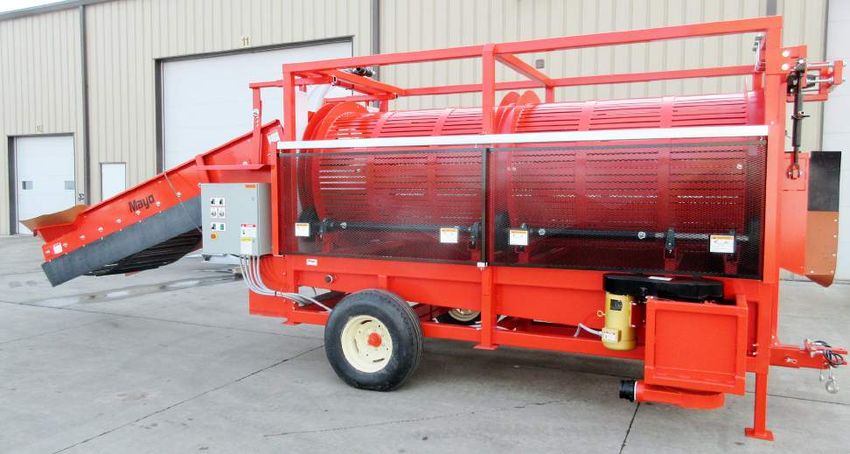
MAYO MANUFACTURING, INC. LIMITED WARRANTY
THE FOLLOWING WARRANTIES FOR MACHINERY, EQUIPMENT OR PARTS SOLD BY MAYO MANU-
FACTURING, INC. ARE IN LIEU OF ALL OTHER WARRANTIES, EXPRESSED OR IMPLIED, OR THOSE
WARRANTIES IMPOSED BY STATUE, INCLUDING, BUT NOT LIMITED TO ANY AND ALL IMPLIED
WARRANTIES OR MERCHANTABILITY AND FITNESS FOR A PARTICULAR PURPOSE AND OF ANY
AND ALL OTHER WARRANTY OBLIGATIONS ON THE PART OF MAYO MANUFACTURING, INC. (The
Company).

The Company warrants the machinery, equipment or parts delivered against faulty workmanship or the use
of parts delivered against faulty workmanship or the use of defective materials for a period of one (1) year
from the date of shipment.

The Company's warranties set forth above are the only warranties made by the Company and shall not be
enlarged, diminished or affected by, and no obligation or liability shall arise out of the Company's rendering
technical or other advice or service in connection with the machinery, equipment or parts.

Parts or components furnished to the Company by third persons are guaranteed only to the extent of the
original manufacturer's guarantee to the Company, a copy of which will be supplied to the Purchaser upon
written request to the Company.

LIABILITY

THE COMPANY'S SOLE AND EXCLUSIVE MAXIMUM LIABILITY, AND PURCHASER'S SOLE AND EX-
CLUSIVE REMEDY under the above warranty shall be, at the Company's option, the repair, or replacement
of the machine, equipment or part which is found to be defective due to faulty workmanship or defective
materials, and is returned by the Purchaser to the Company within the warranty period. Shipment both
ways and in transit damage shall be at the purchaser's risk and expense. If the Company elects to repair or
replace the machine, equipment, or part, the Company will have a reasonable time within which to do so.

The remedies set forth above are available upon the following conditions:

1. Purchaser has promptly notified Company upon discovery that the machinery, equipment, or parts are
   defective due to faulty workmanship or defective materials; and
2. Purchaser provides Company with a detailed description of the deficiencies; and
3. Company's examination discloses that the alleged deficiencies exist and were not caused by accident,
   fire, misuse, neglect, alteration, or any other hazard or by Purchaser's improper installation, use or
   maintenance.

Such repair or replacement shall constitute fulfilment of all Company's liability to Purchaser, whether based
on contract or tort.

This warranty does not apply to any machine that has been altered outside the factory in any way so as,
in the judgement of Mayo, to affect its operation, reliability or safety, or which has been subject to misuse,
neglect or accident.

In the event the Company breach any other provisions of the Purchase Agreement, the Company's EX-
CLUSIVE MAXIMUM LIABILITY AND PURCHASER'S EXCLUSIVE REMEDY, whether in contract or tort,
otherwise shall not in any event exceed the contract price for the particular machine, piece of equipment or
parts involved.

IN NO EVENT SHALL COMPANY BE LIABLE TO ANYONE FOR SPECIAL, COLLATERAL, INCIDENTAL,
OR CONSEQUENTIAL DAMAGES FOR BREACH OF ANY PROVISIONS OF THIS CONTRACT OR WAR-
RANTY. SUCH EXCLUDE DAMAGES INCLUDE, BUT ARE NOT LIMITED TO, costs of REMOVAL AND
REINSTALLATION OF ITEMS, Loss of GOODWILL, LOSS OF PROFITS, LOSS OF USE OR INTERRUP-
TION OF BUSINESS.

                             WARRANTY VOID IF NOT REGISTERED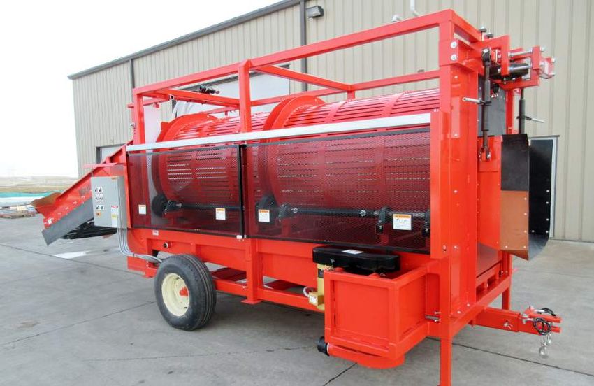
MAYO MANUFACTURING, INC.

                               BARREL WASHER MODEL 824
WARRANTY REGISTRATION FORM & INSPECTION REPORT

WARRANTY REGISTRATION
This form must be filled out by the dealer and signed by both the dealer and the customer at the time of
delivery.

Customer’s Name_ __________________________                Dealer's Name____________________________

Address___________________________________                 Address_________________________________

City, State/Prov., Code________________________            City, State/Prov., Code______________________

Phone Number ( _____ ) _ ___________________

Washer Model______________________________

Serial Number______________________________

Delivery Date_______________________________

 DEALER INSPECTION REPORT                                  SAFETY
 ______ Inspect Electrical System
                                                    ______ All Decals Installed and Legible
 ______ Lubricate Machine
                                                    ______ Review Operating and Safety Instructions
 ______ Drive Chains Tensioned and Aligned
 ______ Speed Reducer Gearboxes Oil Level Checked
 ______ Check Condition of Barrel Drive Rolls
 ______ Check Functioning of Water Pan Float Switch
 ______ Check Condition of Chain/Sprocket Setting
 ______ Check that all Water Holes Flow Freely
 ______ Check Elevator Conveyor Tension and
 ______ Alignment

I have thoroughly instructed the buyer on the above described equipment which review included the Operator’s
Manual content, equipment care, adjustments, safe operation and applicable warranty policy.

Date _ _______________________________           Dealer’s Rep. Signature_____________________________

Signature_____________________________

The above equipment and Operator’s Manual have been received by me and I have been thoroughly instructed
as to care, adjustments, safe operation and applicable warranty policy.

Date_________________________________            Owner's Signature_________________________________

                                  WHITE           YELLOW               PINK

                              MAYO MFG., INC.     DEALER            CUSTOMER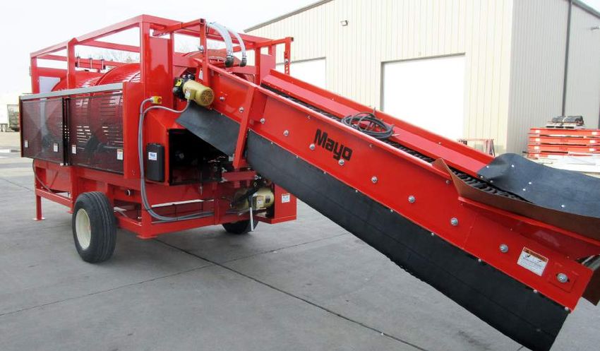

SERIAL NUMBER LOCATION
Always give your dealer the serial number of your Mayo Barrel Washer when ordering parts or requesting
service or other information.

The serial number plate is located where indicated. Please mark the number in the space provided for easy
reference.

SERIAL NUMBER LOCATION

                 Model Number ________________________________

                 Serial Number ________________________________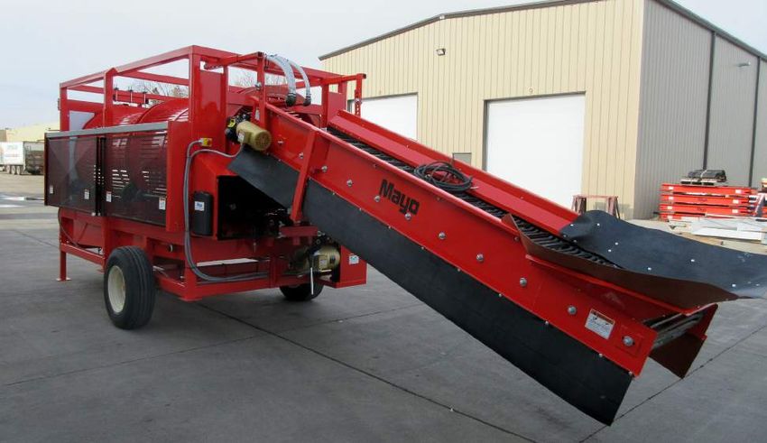
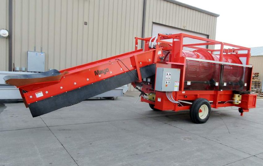
TABLE OF CONTENTS
SECTION			    DESCRIPTION				                                                    PAGE

 1            Introduction .......................................................... 1
 2            Safety..................................................................... 3
     2.1      General Safety........................................................ 4
     2.2      Equipment Safety Guidelines................................. 5
     2.3      Storage Safety........................................................ 5
     2.4      Safety Training........................................................ 6
     2.5      Safety Signs............................................................ 6
     2.6      Installation Safety................................................... 7
     2.7      Preparation Safety.................................................. 7
     2.8      Lock-Out Tag-Out Safety........................................ 7
     2.9      Operating Safety..................................................... 8
     2.10     Maintenance Safety................................................ 8
     2.11     Electrical Safety...................................................... 9
     2.12     Transport Safety...................................................... 9
     2.13     Employee Sign-Off Form.......................................10
 3            Safety Sign Locations.........................................11
 4            Operation............................................................. 15
     4.1      To the New Operator or Owner............................. 15
     4.2      Machine Components........................................... 16
     4.3      General Operation Theory.................................... 18
     4.4      Machine Break-In.................................................. 19
     4.5      Pre-Operation Checklist........................................ 20
     4.6      Controls................................................................ 21
     4.7      Machine Preparation............................................. 24
     4.8      Operating.............................................................. 28
     4.9      Storage................................................................. 35
     4.10     Transport............................................................... 36
 5            Service and Maintenance................................... 41
     5.1      Service.................................................................. 41
     5.2      Maintenance......................................................... 51
 6            Trouble Shooting................................................ 61
 7            Specifications..................................................... 63
     7.1      Mechanical............................................................ 63
     7.2      Bolt Torque............................................................ 64
     7.3      Electrical Schematic............................................. 65
 8            Index.................................................................... 67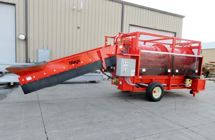
1      INTRODUCTION
Congratulations on your choice of a Mayo Model 824 Barrel Washer and welcome to Mayo's quality line of po-
tato handling equipment. This equipment is designed and manufactured to meet the needs of a discriminating
buyer in the agricultural industry for the loading, unloading, processing and storing of harvest yields.

Safe, efficient and trouble free operation of your new Mayo Barrel Washer requires that you, and anyone else
who will be operating or maintaining the Barrel Washer, read, understand and practice ALL of the Safety, Opera-
tion, Maintenance and Troubleshooting recommendations contained within this Operator's Manual.

This manual applies to all Model 824 Barrel Washers manufactured by Mayo. Certain options may be available
to specifically tailor the Barrel Washer to your operation and may not be included in this manual. Please contact
the manufacturer regarding additional information about these options. Use the Barrel Washer Table of Contents
and Index as a guide to find specific information.

Keep this manual handy for frequent reference and so that it will be passed on to new operators or owners. Call
your Mayo dealer if you need assistance, information or additional copies of this manual.

MACHINE ORIENTATION - The discharge end of the Barrel Washer is the front. The control panel is on the right
side of the frame.

                                                                                                               1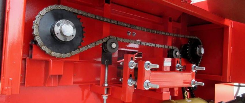
2
2     SAFETY

                                   SAFETY ALERT SYMBOL

                                                                       The Safety Alert symbol identifies
This Safety Alert symbol means                                         important safety messages on your
ATTENTION! BECOME ALERT!                                               Mayo Barrel Washer and in the manu-
YOUR SAFETY IS INVOLVED!                                               al. When you see this symbol, be alert
                                                                       to the possibility of personal injury or
                                                                       death. Follow the instructions in the
                                                                       safety message.

                                Why is SAFETY important to you?

                                                                 Accidents Disable and Kill
              3 Big Reasons                                      Accidents Cost You Money
                                                                 Accidents Can Be Avoided

                                                    DANGER -          Indicates an imminently hazardous situ-
                                                                      ation that, if not avoided, will result in
                                                                      death or serious injury. This signal word
                                                                      is to be limited to the most extreme situa-
                                                                      tions, typically for machine components
                                                                      that, for functional purposes, cannot be
SIGNAL WORDS:                                                         guarded.
Note the use of the signal words DANGER,
WARNING and CAUTION with the safety
messages. The appropriate signal word for each
                                                    WARNING -         Indicates a potentially hazardous situ-
                                                                      ation that, if not avoided, could result
message has been selected using the following
                                                                      in death or serious injury, and includes
guide-lines:
                                                                      hazards that are exposed when guards
                                                                      are removed. It may also be used to alert
                                                                      against unsafe practices.

                                                    CAUTION -         Indicates a potentially hazardous situ-
                                                                      ation that, if not avoided, may result in
                                                                      minor or moderate injury. It may also be
                                                                      used to alert against unsafe practices.

If you have any questions not answered in this manual or require additional copies or the manual is damaged,
please contact your dealer or Mayo, P.O. Box 497, Bus Highway 2, East Grand Forks, Minnesota, 56721.
(Telephone) 218-773-1234, (FAX) 218-773-6693 or toll free at 1-800-223-5873.

                                                                                                               3
SAFETY 2.1 GENERAL SAFETY
YOU are responsible for the SAFE operation and 1. Read and understand the
maintenance of your Mayo Barrel Washer. YOU must Operator's Manual and all safe-
ensure that you and anyone else who is going to op- ty signs before supplying power
erate, maintain or work around the Barrel Washer be to, operating, maintaining or ad-
familiar with the operating and maintenance proce- justing the Barrel Washer.
dures and related SAFETY information contained in
this manual. This manual will take you step-by-step 2. Only trained, competent persons shall operate the
through your working day and alerts you to all good Barrel Washer. An untrained operator is not quali-
safety practices while operating the Barrel Washer. fied to operate this machine.
Remember, YOU are the key to safety. Good safety 3. Provide a first-aid kit for use in
practices not only protect you but, also the people case of an accident. Store in a
around you. Make these practices a working part of highly visible place.
your safety program. Be certain that EVERYONE op-
erating this machine is familiar with the procedures
recommended and follows safety precautions. Re- 4. Provide a fire extinguisher for use in
member, most accidents can be prevented. Do not case of an accident. Store in a highly
risk injury or death by ignoring good safety practices. visible place.
• Read and understand the Operator's Manual 5. Install and properly secure all guards
and all safety signs before supplying power to, and shields before operating.
operating, maintaining or adjusting the Barrel
Washer. 6. Wear appropriate
protective gear.
• Barrel Washer owners must give operating in- This list includes
structions to operators or employees before al- but is not limited to:
lowing them to operate the Barrel Washer, and at
least annually thereafter. - Protective
shoes with slip
• The most important safety device on this equip- resistant soles
ment is a SAFE operator. It is the operator’s re- - Protective
sponsibility to read and understand ALL Safety glasses or
and Operating instructions in the manual and to goggles
follow these. Most accidents can be avoided. - Heavy gloves
- Hearing protection
• A person who has not read and understood all op-
erating and safety instructions is not qualified to 7. Turn machine OFF, place all controls in their OFF
operate this machine. An untrained operator ex- position, shut down and lockout power supply and
poses himself and bystanders to possible serious wait for all moving parts to stop before servic-
injury or death. ing, adjusting, maintaining, repairing or cleaning.
(Safety lockout devices are available through your
• Do not modify the equipment in any way. Mayo dealer parts department).
Unauthorized modification may impair the func-
tion and/or safety and could affect the life of the 8. Know the emergency medical center number for
equipment. your area.
• Think SAFETY! Work SAFELY! 9. Review safety related items with all operators
annually.
42.2 EQUIPMENT SAFETY GUIDELINES
1. Safety of the operator and bystanders is one of 9. In addition to the design and configuration of this
the main concerns in designing and developing a implement, including Safety Signs and Safety
machine. However, every year many accidents oc- Equipment, hazard control and accident preven-
cur which could have been avoided by a few sec- tion are dependent upon the awareness, con-
onds of thought and a more careful approach to cern, prudence, and proper training of personnel
handling equipment. You, the operator, can avoid involved in the operation, transport, maintenance,
many accidents by observing the following pre- and storage of the machine. Refer also to Safety
cautions in this section. To avoid personal injury or Messages and operation instruction in each of the
death, study the following precautions and insist appropriate sections of the auxiliary equipment
those working with you, or for you, follow them. and machine Manuals. Pay close attention to the
Safety Signs affixed to the auxiliary equipment
2. In order to provide a better view, certain photo- and the machine.
graphs or illustrations in this manual may show an
assembly with a safety shield removed. However,
equipment should never be operated in this con-
dition. Keep all shields in place. If shield removal
becomes necessary for repairs, replace the shield
prior to use.
2.3 STORAGE SAFETY
3. Replace any safety sign or instruction sign that is
not readable or is missing. Location of such safety 1. Store the Barrel Washer on a firm level surface.
signs is indicated in this manual.
2. If required, make sure the unit is firmly blocked up.
4. Never use alcoholic beverages or drugs which
can hinder alertness or coordination while oper- 3. Drain all the water from the collector basin in the
ating this equipment. Consult your doctor about bottom of the frame and recirculation system.
operating this machine while taking prescription
medications. 4. Make certain that all mechanical locks are safely
and positively connected before storing.
5. Under no circumstances should young chil-
dren be allowed to work with this equipment. 5. Store away from areas of human activity.
Do not allow persons to operate or assemble
this unit until they have read this manual and 6. Do not allow children to play on or around the
have developed a thorough understanding of stored Barrel Washer.
the safety precautions and of how it works.
Review the safety instructions with all users 7. Lock out power by turning off master control panel,
annually. junction box or unplugging the power cord and
padlocking the door shut to prevent electrocution
6. This equipment is dangerous to children and or unauthorized start up of the Barrel Washer.
persons unfamiliar with its operation. The opera-
tor should be a responsible, properly trained and
physically able person familiar with farm machin-
ery and trained in this equipment's operations.
If the elderly are assisting with farm work, their
physical limitations need to be recognized and
accommodated.
7. Never exceed the limits of a piece of machinery. If
its ability to do a job, or to do so safely, is in ques-
tion - DON'T TRY IT.
8. Do not modify the equipment in any way.
Unauthorized modification result in serious injury
or death and may impair the function and life of the
equipment.
52.4 SAFETY TRAINING 2.5 SAFETY SIGNS
1. Safety is a primary concern in the design and man- 1. Keep safety signs clean and legible at all times.
ufacture of our products. Unfortunately, our efforts
to provide safe equipment can be wiped out by a 2. Replace safety signs that are missing or have be-
single careless act of an operator or bystander. come illegible.
2. In addition to the design and configuration of 3. Replaced parts that displayed a safety sign should
equipment, hazard control and accident preven- also display the current sign.
tion are dependent upon the awareness, con-
cern, prudence and proper training of personnel 4. Safety signs displayed in Section 3 each have a
involved in the operation, transport, maintenance part number in the lower right-hand corner. Use
and storage of this equipment. this part number when ordering replacement
parts.
3. It has been said, "The best
safety feature is an informed, 5. Safety signs are available from your authorized
careful operator." We ask you Distributor or Dealer Parts Department or the
to be that kind of an operator. factory.
It is the operator's responsibility
to read and understand ALL Safety and Operating How to Install Safety Signs:
instructions in the manual and to follow these.
Accidents can be avoided. • Be sure that the installation area is clean and dry.
4. Working with unfamiliar equipment can lead • Be sure temperature is above 50°F (10°C).
to careless injuries. Read this manual, and the
manual for your auxiliary equipment, before • Determine exact position before you remove the
assembly or operating, to acquaint yourself backing paper. (See Section 3).
with the machines. If this machine is used by
any person other than yourself. It is the ma- • Remove the smallest portion of the split backing
chine owner's responsibility to make certain paper.
that the operator, prior to operating:
• Align the sign over the specified area and careful-
a. Reads and understands the operator's ly press the small portion with the exposed sticky
manuals. backing in place.
b. Is instructed in safe and proper use. • Slowly peel back the remaining paper and care-
fully smooth the remaining portion of the sign in
5. Know your controls and how to stop pilers, sting- place.
ers, Barrel Washers, conveyors and any other aux-
iliary equipment quickly in an emergency. Read • Small air pockets can be pierced with a pin and
this manual and the one provided with your other smoothed out using the piece of sign backing
equipment. paper.
6. Train all new personnel and review instructions
frequently with existing workers. Be certain only
a properly trained and physically able person will
operate the machinery. A person who has not read
and understood all operating and safety instruc-
tions is not qualified to operate the machine. An
untrained operator exposes himself and bystand-
ers to possible serious injury or death. If the elderly
are assisting with farm work, their physical limita-
tions need to be recognized and accommodated.
62.6 PREPARATION 2.7 INSTALLATION SAFETY
1. Never operate the Barrel Washer and auxiliary 1. Disconnect and remove all mechanical locks, an-
equipment until you have read and complete- chor chains and any other transport devices that
ly understand this manual, the auxiliary equip- would hinder or prohibit the normal functioning of
ment Operator's Manual, and each of the Safety the Barrel Washer upon start up. Serious damage
Messages found on the safety signs on the Barrel to the machine and/or personal injury to the op-
Washer and auxiliary equipment. erator and bystanders may result from attempting
to operate the machine while mechanical locking
2. Personal protec- devices are still attached.
tion equipment in-
cluding hard hat, 2. Position the machine on firm, level ground before
safety glasses, operating.
safety shoes, and
gloves are recom- 3. Have at least one extra person available to assist
mended during when elevating, moving or connecting to other
assembly, instal- equipment.
lation, operation,
adjustment, main- 4. Make certain that sufficient amperage, at the prop-
taining, repairing, removal, or moving the imple- er voltage and frequency (60Hz) is available be-
ment. Do not allow long hair, loose fitting clothing fore connecting power. All wiring should comply
or jewelry to be around equipment. with ANSI/NFPA 70 electrical requirements. If you
are uncertain, have a licensed electrician provide
3. PROLONGED EXPOSURE power to the machine.
TO LOUD NOISE MAY CAUSE
PERMANENT HEARING LOSS! 5. If using Barrel Washer as part of material handling
Motors or equipment attached system, anchor securely to other equipment be-
can often be noisy enough to fore starting.
cause permanent, partial hear-
ing loss. We recommend that you
wear hearing protection on a full-time basis if the
noise in the Operator's position exceeds 80db.
Noise over 85db on a long-term basis can cause
severe hearing loss. Noise over 90db adjacent to
the Operator over a long-term basis may cause
2.8 LOCK-OUT TAG-OUT SAFETY
permanent, total hearing loss. NOTE: Hearing 1. Establish a formal Lock-Out Tag-Out program for
loss from loud noise (from tractors, chain saws, ra- your operation.
dios, and other such sources close to the ear) is
cumulative over a lifetime without hope of natural 2. Train all operators and service personnel before
recovery. allowing them to work around the Barrel Washer.
4. Clear working area of debris, trash or hidden ob- 3. Provide tags at the work site and a sign-up sheet
stacles that might be hooked or snagged, causing to record tag out details.
injury, damage or tripping.
4. Do not service or maintain the Barrel Washer un-
5. Operate only in daylight or good artificial light. less motors are OFF and the power locked out at
the master panel. Keep others away.
6. Be sure machine is properly anchored, adjusted
and in good operating condition.
7. Ensure that all safety shielding and safety signs
are properly installed and in good condition.
8. Before starting, give the machine a "once over" for
any loose bolts, worn parts, cracks, leaks, frayed
belts and make necessary repairs. Always follow
maintenance instructions.
72.9 OPERATING SAFETY 2.10 MAINTENANCE SAFETY
1. Make sure that anyone who will be operating the 1. Read and understand all the information contained
Barrel Washer or working on or around the unit in the Operator's Manual regarding operating, ser-
reads and understands all the operating, main- vicing, adjusting, maintaining and repairing.
tenance and safety information in the operator's
manual. Also read and follow the instructions in 2. Turn machine OFF, shut down and lock out
the manuals of other equipment in the system. power supply (safety lockout devices are avail-
able through your Mayo dealer parts depart-
2. Turn machine OFF, shut down and lock out ment), relieve hydraulic pressure and wait for
power supply (safety lockout devices are avail- all moving parts to stop before servicing, ad-
able through your Mayo dealer parts depart- justing, maintaining or repairing.
ment) and wait for all moving parts to stop
before servicing, adjusting, maintaining or 3. Follow good shop practices:
repairing.
- Keep service area clean
3. Establish a lock-out tag-out policy for the work site. and dry.
Be sure all personnel are trained in and follow all - Be sure electrical out-
procedures. Lock-out tag-out all power sources lets and tools are properly
before servicing the unit or working around load- grounded.
ing/unloading equipment. - Use adequate light for the
job at hand.
4. Install and properly secure all guards and shields
before operating. 5. Make sure all guards and doors are in place
and properly secured when operating the Barrel
5. Replace all worn or failed components immediately. Washer.
6. Keep hands, feet, hair and clothing away from all 6. Always use personal protection devices such as
moving parts. eye, hand and hearing protectors, when perform-
ing any service or maintenance.
7. Clear the area of bystanders, especially small chil-
dren, before starting. 7. Where replacement parts are necessary for peri-
odic maintenance and servicing, genuine factory
8. Make sure all control switches are in the off posi- replacement parts must be used to restore your
tion before connecting power supply. equipment to original specifications. The manufac-
turer will not be responsible for injuries or dam-
9. Insure all water system and supply components in ages caused by use of unapproved parts and/or
good condition before starting. accessories.
10. Keep all electrical components tight, dry and in 8. A fire extinguisher and first
good repair. aid kit should be kept read-
ily accessible while perform-
11. Before supplying electrical power to the machine, ing maintenance on this equipment.
be sure that you have adequate amperage at
the proper phase and voltage to run it by follow- 9. Periodically tighten all bolts, nuts and screws and
ing ANSI/NFPA 70 Wiring Standard. If you do not check that all cotter pins are properly installed to
know or are unsure, consult a licensed electrician. ensure unit is in a safe condition.
12. Keep the working area clean and dry. 10. When completing a maintenance or service func-
tion, make sure all safety shields and devices are
13. Review safety instructions annually. installed before placing unit in service.
11. Do not work on Barrel Washer
electrical system unless the pow-
er cord is unplugged or the power
supply is locked out. Lock-out tag-
out power source before perform-
ing any maintenance work.
82.11 ELECTRICAL SAFETY 2.12 TRANSPORT SAFETY
1. Have only a qualified licensed electrician supply 1. Make certain that you are in compliance with local,
power. All wiring should comply with ANSI/NFPA state/provincial and federal regulations regard-
70 electrical requirements. Always follow local, ing transporting agricultural equipment on public
state/provincial and federal electrical codes. roadways.
2. Make certain that the Barrel Washer is properly 2. Make certain that all wheels and tires are in good
grounded at the power source. repair and that tires are inflated to proper pressure.
Do not under-inflate or over-inflate.
3. Make certain that all electrical switches are in the
OFF position before plugging the Barrel Washer 3. Make certain that all wheel bolts/lug nuts are tight-
in. ened to proper torque specifications (refer to spec-
ification chart in Section 7.2).
4. Turn machine OFF, shut down and lock out
power supply (safety lockout devices are avail- 4. Raise elevator fully up before transporting to pre-
able through your Mayo dealer parts depart- vent dragging the hopper on the ground when go-
ment), relieve hydraulic pressure and wait for ing through low spots.
all moving parts to stop before servicing, ad-
justing, maintaining or repairing. 5. Raise and secure the frame outriggers and secure
with set screws before transporting or moving.
5. Disconnect power before resetting any motor or
breaker overload. 6. Wrap up and tie all loose electrical ends to the
frame.
6. Replace any damaged electrical plugs, cords, 7. Be sure that any necessary SMV (slow moving ve-
switches and components immediately. hicle) signs, reflectors and lights required by law
are in proper place and are clearly visible to on-
7. Do not work on Barrel Washer electrical system coming and overtaking traffic.
unless the power cord is unplugged or the power
supply is locked-out tagged-out. 8. Be sure that the Barrel Washer is positively hitched
to the towing vehicle. Use a safety cable to assure
a safe hitch hook-up when transporting.
9. Follow local regulations regarding maximum
weight, width and length when transporting.
10. Do not exceed 15 MPH (25 Km/H). Reduce speed
on rough roads and surfaces.
11. Do not allow anyone to ride on the Barrel Washer
or towing vehicle during transport.
12. Always use hazard flashers on the towing vehicle
when transporting.
13. Always use pilot vehicles in front and behind when
towing on a public road.
92.13 EMPLOYEE SIGN-OFF FORM
Mayo Manufacturing, Inc. follows the general Safety Standards specified by the American Society of Agricultural
Engineers (ASABE) and the Occupational Safety and Health Administration (OSHA). Anyone who will be op-
erating and/or maintaining a Mayo built machine must read and clearly understand ALL Safety, Operating and
Maintenance information presented in this manual.
Do not operate or allow anyone else to operate this equipment until such information has been reviewed. Annu-
ally review this information before the season start-up.
Make these periodic reviews of SAFETY and OPERATION a standard practice for all of your equipment. We feel
that an untrained operator is unqualified to operate this machine.
A sign-off sheet is provided for your record keeping to show that all personnel who will be working with the
equipment have read and understand the information in the Operator’s Manual and have been instructed in the
operation of the equipment.
SIGN-OFF FORM
DATE EMPLOYEE'S SIGNATURE EMPLOYER'S SIGNATURE
103 SAFETY SIGN LOCATIONS
The types of safety signs and locations on the equipment are shown in the illustrations that follow. Good safety
requires that you familiarize yourself with the various Safety Signs, the type of warning and the area, or particu-
lar function related to that area, that requires your SAFETY AWARENESS.
• Think SAFETY! Work SAFELY!
A
DD
F
E D D D D
B E E D
A
C D C
A B
REMEMBER - If Safety Signs have been damaged, removed, become illegible or parts replaced without safety
signs, new signs must be applied. New safety signs are available from your authorized dealer.
11The types of safety signs and locations on the equipment are shown in the illustrations that follow. Good safety
requires that you familiarize yourself with the various Safety Signs, the type of warning and the area, or particu-
lar function related to that area, that requires your SAFETY AWARENESS.
• Think SAFETY! Work SAFELY!
D
F D
A B D D
E D
D
C
C D
REMEMBER - If Safety Signs have been damaged, removed, become illegible or parts replaced without safety
signs, new signs must be applied. New safety signs are available from your authorized dealer.
12The types of safety signs and locations on the equipment are shown in the illustrations that follow. Good safety
requires that you familiarize yourself with the various Safety Signs, the type of warning and the area, or particu-
lar function related to that area, that requires your SAFETY AWARENESS.
• Think SAFETY! Work SAFELY!
A
C
D D
E D D D
E
D
A
D
C
E
E F
REMEMBER - If Safety Signs have been damaged, removed, become illegible or parts replaced without safety
signs, new signs must be applied. New safety signs are available from your authorized dealer.
13The types of safety signs and locations on the equipment are shown in the illustrations that follow. Good safety
requires that you familiarize yourself with the various Safety Signs, the type of warning and the area, or particu-
lar function related to that area, that requires your SAFETY AWARENESS.
• Think SAFETY! Work SAFELY!
DD
E
D
C
C
E
E
REMEMBER - If Safety Signs have been damaged, removed, become illegible or parts replaced without safety
signs, new signs must be applied. New safety signs are available from your authorized dealer.
144 OPERATION
OPERATING SAFETY
• Make sure that anyone who will be operating the • Keep hands, feet, hair and clothing away from
Barrel Washer or working on or around the unit all moving parts.
reads and understands all the operating, main-
• Clear the area of bystanders, especially small
tenance and safety information in the operator's
children, before starting.
manual. Also read and follow the instructions in
the manuals of other equipment in the system. • Make sure all control switches are in the off posi-
tion before connecting power supply.
• Turn machine OFF, shut down and lock out
power supply (safety lockout devices are
• Insure all water system and supply components
available through your Mayo dealer parts
in good condition before starting.
department) and wait for all moving parts to
stop before servicing, adjusting, maintaining • Keep all electrical components tight, dry and in
or repairing. good repair.
• Establish a lock-out tag-out policy for the work • Before supplying electrical power to the ma-
site. Be sure all personnel are trained in and chine, be sure that you have adequate amper-
follow all procedures. Lock-out tag-out all pow- age at the proper phase and voltage to run it by
er sources before servicing the unit or working following ANSI/NFPA 70 Wiring Standard. If you
around loading/unloading equipment. do not know or are unsure, consult a licensed
electrician.
• Install and properly secure all guards and shields
before operating. • Keep the working area clean and dry.
• Replace all worn or failed components • Review safety instructions annually.
immediately.
4.1 TO THE NEW OPERATOR OR OWNER
The Mayo Manufacturing Barrel Washer is designed Follow all safety instructions exactly. Safety is
to wash potatoes to remove dirt, mud and residue pri- everyone's business. By following recommended
or to placing in storage or transporting for processing. procedures, a safe working environment is pro-
Be familiar with the machine before starting. vided for the operator, bystanders and the area
around the worksite. Untrained personnel are not
It is the responsibility of the owner or operator qualified to operate this machine.
to read this manual and to train all other opera-
tors before they start working with the machine. Many features incorporated into this machine are the
Follow all safety instructions exactly. Safety is result of suggestions made by customers like you.
everyone's business. By following recommended Read this manual carefully to learn how to operate the
procedures, a safe working environment is pro- machine safely and how to set it to provide maximum
vided for the operator, bystanders and the area efficiency. By following the operating instructions in
around the worksite. Untrained operators are not conjunction with a good maintenance program, your
qualified to operate the machine. Barrel Washer will provide many years of trouble-free
service.
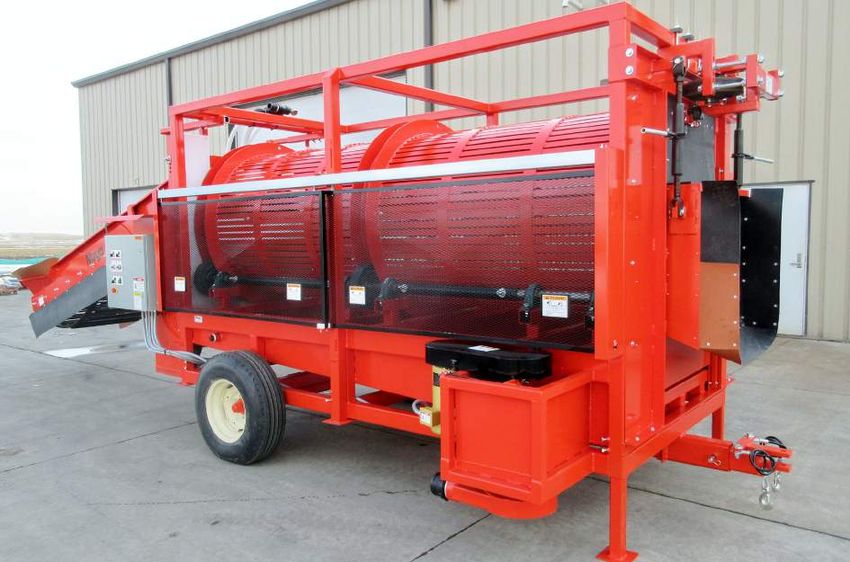
154.2 MACHINE COMPONENTS
The Mayo Manufacturing Barrel Washer consists of An electric motor, speed reduction gearbox and roller
an intake elevator, tumbling drum, wash bed and dis- chain drive system on the rear of the frame turns and
charge gate for cleaning potatoes prior to shipment supports the drum for washing. Wash water is dis-
for processing. Generally a Barrel Washer is a com- tributed by 3 internal pipes with 1/4 inch holes in the
ponent within a conveying line and is used to clean bottom of the tubes to wash/clean the potatoes. Wash
and wash the potatoes. water flows into the bottom of the frame into the water
compartment and removed by the sump pump on the
Customers provide conveyors to move the potatoes right front corner of the frame. The water should be
into and out of the Barrel Washer as part of the po- pumped into a settling tank, filtered and recycled.
tato preparation line. Restrict the discharge to keep
the potatoes in the drum and wash bed area a longer Direct a flow of supplemental water into the top of the
time to reduce the speed the potatoes move through water collecting tank from both sides to flush the dirt
the machine to provide more washing time. and debris removed from the potatoes into the sump
for removal from the system. A float switch in the left
5 rubber wheels/rollers on each side of the drum rear corner of the water collection pan starts and
turn and support the drum when operating. Rubber stops the sump pump to drain the water and sludge
wheels/rollers on each end of the drum centre the from the bottom of the pan and prevent plugging the
drum in the frame while turning. system.
Tumbler slats are installed at 2 positions on the inside An electric motor through a speed reducing gearbox
of the drum to roll/tumble the potatoes as they move is mounted on the top left side of the elevator to power
through the drum to expose all sides of the potato to the elevator. A potato chain is used as the conveyor
the wash water. to allow dirt to fall off the potatoes before they go into
the wash drum.
A Wash Drum H Water Tubes/Pipes P Sump Pump Discharge
B Input Elevator J Drum Drive System Q Flush Water Intake
C Discharge K Drum Drive Gearbox R Water Collection Tank
D Elevator Chain L Elevator Drive S Tumbler Rods
E Turning Wheels M Control Panel T Outriggers
F Centering Wheels N Sump Pump Drive System
G Water Lines O Sump Pump
G
A
L
B
J
D
Q
T T
T
FIG. 1 MACHINE COMPONENTS
16F
G
A
B M
E C
E E E
Q N
R
T
T
P O
T
A
H H H
N
S S
H HH
B
J
J
K
174.3 GENERAL OPERATION THEORY
A Barrel Washer is positioned in the line of conveying
equipment that loads trucks to take the potatoes for
processing. This unit can be located at a storage or
transfer facility and used prior to the potatoes being
loaded into the transport truck.
Fresh and recycled (cleaned or filtered) water must
be provided to the machine by the customer at the re-
quired volume and pressure for optimum performance.
Insufficient volume and pressure will compromise the
washing performance.
Potatoes are fed into the intake elevator by one of
several types of conveying machines which could
include, but is not limited to a telescoping conveyor, a
straight conveyor, a sizing conveyor, a chain conveyor,
a transport truck, a holding hopper, etc.
When the potatoes are scrubbed, cleaned and finally
rinsed with clean water at the end of the wash drum,
they are discharged out the back of the machine.
The customer must provide a means to remove the
clean potatoes from the washer as they are discharged.
Minimize all drop heights to prevent bruising of the
potatoes.
Barrel Washer
Positioned
FIG. 2 POSITIONED (TYPICAL)
184.4 MACHINE BREAK-IN
Although there are no operational restrictions on the
Barrel Washer when used for the first time, it is rec-
ommended that the following mechanical items be
checked:
A. Before Starting:
1. Read Barrel Washer and auxiliary equipment
manuals before starting.
2. Turn gearbox breather 1/4 turn to open breath-
er and remove tag.
Elevator
B. After operating for 1/2 hour:
1. Retorque all fasteners and hardware.
2. Check that all electrical connections are
tight and cords are routed out of the way or
protected.
3. Check the integrity of the water supply, piping
and discharge holes. Clean discharge holes if
any are plugged or have a distorted discharge
pattern.
4. Inspect drum, drive wheels/rollers and eleva-
tor for entangled material. Remove material.
Drum
5. Check the alignment and tension of the el-
evator, drum and sump pump drive systems. FIG. 3 BREATHERS
Realign or tighten as required.
6. Check the centering of the drum in the frame.
Re-center if required.
7. Check oil level in the speed reducing gearbox-
es for the elevator and drum drive systems.
Top up as required.
8. Clean the water collection tank under the
drum of all the mud, soil and debris.
9. Lubricate all grease fillings.
C. After 2, 5 and 10 hours of operation:
1. Repeat steps 1 through 9 from Section B.
2. Then go to the regular servicing and mainte-
nance schedule as defined in the Maintenance
Section.
194.5 PRE-OPERATION CHECKLIST
Safe and efficient operation of your new Barrel Wash-
er requires that each operator reads and follows all
safety precautions and operating procedures con-
tained in this section. Performing the following pre-
operation checklist is important for personal safety as
well as for continued mechanical soundness and lon-
gevity of your new Mayo Barrel Washer. The check-
list should be performed before operating the Barrel
Washer and prior to each operation thereafter.
1. Lubricate the machine according to the schedule
prescribed in the "Maintenance Section".
2. Insure that proper protective gear is in good repair
and available for use by each operator. Make cer-
tain that each operator uses the protective gear.
Protective gear includes but, is not limited to:
- Leather gloves
- Safety glasses or
face shield
- Full length protec-
tive clothing
- Steel toed boots
with slip resistant Outriggers (Typical)
soles.
3. Insure that all safety guards and shields are in
good repair and securely in place.
4. Check that all outrages are down and securely an-
chored with their setscrews.
5. Check the integrity of water supply, piping and wa-
ter holes. Clean water holes if any are plugged or
have a distorted discharge pattern. Clean water
collection tank.
6. Inspect drum, drive wheels and elevator for entan-
gled material. Remove entangled material.
Elevator
7. Check the alignment and tension of drum and
sump pump drive systems. Realign or tighten as
required.
8. Check oil level in speed reduction gearboxes for
the drum and elevator drives. Top up as required.
9. Check that the elevator conveyor potato chain is
centred on the head and tail sprockets. Adjust if
necessary as outlined in the ‘Maintenance Section’.
10. Check that all electrical connections are tight and
cords are routed out of the way or protected.
11. Be sure the working area is clean and dry to pre-
Water Holes (Typical)
vent tripping or slipping.
FIG. 4 INSPECTION (TYPICAL)
204.6 CONTROLS
It is recommended that all operators review this sec-
tion of the manual to familiarize themselves with the 1 2
location and function of all machine controls before
starting. Some machines may vary slightly due to
custom features but they are similar and all controls 3 4
are labelled.
5 6
1. Drum:
This 2 position rotary switch controls the power 7
to the electric motor that turns the drum. Turn the
switch clockwise to turn ON and counter-clock-
wise to turn OFF.
2. Elevator: FIG. 5 CONTROL PANEL
This 2 position rotary switch controls the power
to the electric motor taht drives the elevator. Turn
the switch clockwise to turn ON and counter-clock-
wise to turn OFF.
3. Drum Speed:
This infinitely variable rotary switch controls the
speed of the electric motor turning the drum. Turn
the switch fully counter-clockwise to stop the drum
and slowly clockwise to start the drum and gradu-
ally increase speed. Normally setting at a relative-
ly slow speed provides adequate tumbling of the
potatoes for cleaning as they move through the
machine.
4. Elevator Speed:
This infinitely variable rotary switch controls the
speed of the electric motor driving the elevator.
Turn the switch fully counter-clockwise to stop the
elevator and slowly clockwise to start the elevator
and gradually increase speed. Set the speed ap-
propriate for the application. The potatoes should
be clean when the exit the drum.
5. Pump:
This 2 position rotary switch controls the power to
the hydraulic pump. Turn the switch clockwise to
turn ON and counter-clockwise to turn OFF.
6. Green Indicator Light:
This green light will be illuminated when the pump
is running. The light goes out when the pump is
turned OFF.
7. Emergency STOP (Control Panel):
This red two-position push-pull switch controls
the power to the machine. Push the switch in to
cut power and turn all functions off. Turn switch
1/4 turn clockwise and switch will pop out. Either
this switch or the frame-mounted emergency stop
switch will cut power to the mchine but both must
be pulled out for the machine to operate.
217. Emergency STOP (Secondary):
This red two-position push-pull switch controls the
power to the machine. Push the switch in to cut
power and turn all functions off. Turn switch 1/4
turn clockwise and switch will pop out. Either this
switch or the control panel-mounted emergency
stop switch will cut power to the mchine but both
must be pulled out for the machine to operate.
FIG. 6 EMERGENCY STOP SWITCH - SECONDARY
8. Master Plug:
Each machine is designed with a plug at the end
of the power cord. Always unplug it before per-
forming any service, maintenance or repairs on
the machine.
FIG. 7 MASTER PLUG
9. Pressure Gauge:
The wash water intake system is equipped with a
pressure gauge that displays the pressure in the
line bringing water to the machine. Normally the
system should be set at 30 - 50 gpm of flow at 35
- 40 psi for the best results. However the system
pressure is dependent upon the pump supplying
the water. The system can accommodate water
flow up to 200 gpm depending on the auxiliary
system components.
FIG. 8 PRESSURE GAUGE
2210. Water Compartment Float Switch:
A switch is mounted on the rear left corner of the
frame on a float that extends into the water com-
partment to monitor the level of the water in the
compartment. When the water level rises, it trips
the switch to engage the sump pump. As the water
is pumped out, the switch engages again to turn
the pump off. This feature prevents the pump from
running continuously.
FIG. 9 FLOAT SWITCH
6. Turnbuckles:
Turnbuckles are used to position the drum angle
and the elevator height. Turn the handle on the
turnbuckle as required to set and position the
drum angle and elevator height appropriate for the
application.
a. Drum Angle.
b. Elevator Height.
Drum Angle
Elevator
FIG. 10 TURNBUCKLES
234.7 MACHINE PREPARATION
The machine must be properly prepared prior to us-
ing. Before starting machine, be sure that the follow-
ing items are appropriate for your machine and oper-
ating requirements:
1. Power:
Have a licensed electrician provide power at
the required voltage, phase and amperage
for your machine by following ANSI/NFPA 70
Wiring Standard. An improper source of power
will cause damage to electrical components
and could create an electrical hazard to the
operator, workers or bystanders.
Be sure to use an extension cord of the correct
specifications for the power being carried. Route
the cord so that it does not interfere with the work-
ing area. Provide appropriate protection when peo-
ple or equipment must go over the cord. Inspect
the cord occasionally to be sure it is not damaged.
Replace immediately if it is damaged.
2. Outrigger Set Screws:
Each side of the machine is designed with three
telescoping outriggers on each side of the frame
that allow the frame to be levelled on any type of
surface. Use the two set screws on each outrigger
to keep the frame level and yet support the weight
of the machine. Tighten set screws to secure.
FIG. 11 OUTRIGGER SET SCREWS
3. Hitch:
Each machine is equipped with a tow hitch on the
rear of the frame. Always configure it in its retract-
ed position to minimize the chance of interfering
with auxiliary equipment or obstructing access to
the machine.
FIG. 12 RETRACTED HITCH
243. Wash Water Supply:
Provide a 30 - 50 gpm (up to 200 gpm) 35- 40
psi source of water to the machine. More water is
recommended if the potatoes are dirty. Normally,
water from the bottom is filtered or cleaned and
then recycled back through the wash system. The
Mayo 12000 Series Recirculating Tank works well a
for recycling and cleaning an adequate supply of
water.
A 2 inch inlet water line supplies water to the mani-
fold which provides water to the 3 wash water lines.
Two small lines on the side and a larger centre line
for a large volume of water when the potatoes are
dirty. Inlet
a. Water Inlet.
b. Centre Line.
c. Side Lines.
c c
b
Wash Lines
c
c
b
Drum
FIG. 13 WASH WATER SUPPLY (TYPICAL)
254. Tank Flush Water Supply:
Each machine is designed with 2 inch inlets on
each side of the water containment tank to wash
the dirt and sludge into the sump pump to keep
the tank flushed out and prevent plugging. Dirty
product can introduce a large amount of soil and
mud into the bottom of the tank and potentially
plug it. Set the water flow to move the dirt into the
sump pump and remove it. Increase the water flow
if mud builds up in the containment tank.
Right
Left
FIG. 14 TANK FLUSH WATER SUPPLY
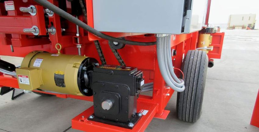
5. Discharge Water:
Each machine is designed with a used water con-
tainment compartment pan and sump pump un-
der the drum. The sump pump removes the used
water, dirt slurry and debris from the compartment b
and moves it to the disposal site. Connect and se-
cure the 3 inch discharge with a tube or piping as a
appropriate.
a. Electric Motor. c
d
b. Pump Drive.
c. Pump.
FIG. 15 DISCHARGE WATER
d. Outlet.
6. Wash Water Depth Switch:
Each used water containment compartment is
equipped with a switch on a float that controls the
power to the sump pump. When the water level ris-
es to a certain level, the switch turns the pump on
to empty the compartment. When the water level
drops to a predetermined level, the switch turns
the pump off. This prevents the pump from running
continuously.
FIG. 16 WASH WATER DEPTH SWITCH
267. Auxiliary Equipment:
Each customer must provide a means of supply-
ing a steady flow of potatoes to the input elevator.
Normally this is done by using another piece of
equipment such as another conveyor or holding
hopper. Always connect the adjacent equipment
securely to the washer to prevent movement. b
a
a. Input
b. Discharge
FIG. 17 AUXILIARY EQUIPMENT
274.8 OPERATING
OPERATING SAFETY
• Make sure that anyone who will be operating the • Keep hands, feet, hair and clothing away from
Barrel Washer or working on or around the unit all moving parts.
reads and understands all the operating, main-
• Clear the area of bystanders, especially small
tenance and safety information in the operator's
children, before starting.
manual. Also read and follow the instructions in
the manuals of other equipment in the system. • Make sure all control switches are in the off posi-
tion before connecting power supply.
• Turn machine OFF, shut down and lock out
power supply (safety lockout devices are
• Insure all water system and supply components
available through your Mayo dealer parts
in good condition before starting.
department) and wait for all moving parts to
stop before servicing, adjusting, maintaining • Keep all electrical components tight, dry and in
or repairing. good repair.
• Establish a lock-out tag-out policy for the work • Before supplying electrical power to the ma-
site. Be sure all personnel are trained in and chine, be sure that you have adequate amper-
follow all procedures. Lock-out tag-out all pow- age at the proper phase and voltage to run it by
er sources before servicing the unit or working following ANSI/NFPA 70 Wiring Standard. If you
around loading/unloading equipment. do not know or are unsure, consult a licensed
electrician.
• Install and properly secure all guards and shields
before operating. • Keep the working area clean and dry.
• Replace all worn or failed components • Review safety instructions annually.
immediately.
Follow this procedure when using the Barrel Washer:
1. Review Section 4.7 Machine Preparation and fol-
low all the instructions.
2. Review and follow the pre-operation checklist
(See Section 4.5).
3. Review the location and function of all controls
(see Section 4.6).
4. Water Intake:
Provide a supply of fresh or recycled water to the
machine through the 2" water line(s) above the in-
take on each side of the water pan. Use the over- Spray Bar
center cam lock coupler provided on each fitting
to secure the line. Be sure the cam locks go over
center to provide a good seal.
Right Side Left Side
FIG. 18 WATER INTAKE
285. Water Discharge:
Attach a 3" pipe or large hose to the pump on the
bottom of the water discharge containment com-
partment to send the used water to the disposal
area. Always dispose of the used water in an en-
vironmentally safe manner.
6. Starting Machine:
a. Clear the area of bystanders. Know where ev-
eryone is before starting.
b. Place all controls in the OFF position.
c. Plug in power cord.
FIG. 19 WATER DISCHARGE OUTLET
d. Turn the power to the machine ON by making
sure both emergency stop switches are pulled
out.
e. Turn the water supply ON.
f. Turn the conveyor ON that moves potatoes
away from the machine.
g. Turn the Barrel Washer drum drive ON.
h. Turn the pump ON that removes the dis-
charge water from the bottom containment
compartment.
i. Turn the elevator ON that moves the potatoes Control Panel
into the drum.
7. Stopping Machine:
a. Turn OFF the elevator.
b. Wait until the potatoes have moved out of the
drum.
c. Turn the conveyor OFF that moves potatoes
away from the machine.
d. Turn the water supply OFF.
e. Turn the pump OFF. Plug
f. Depress one of the emergency stop switches.
NOTE
When the red emergency stop button
on the control panel is depressed, the
operator must go through steps 7:a
through 7:e to turn all controls OFF be-
fore restarting.
8. Emergency STOP:
Depress either of the large red STOP button on
the machine. This will stop the elevator, drum and
pump. Then turn the water supply off. Correct the Emergency Stop - Secondary
problem and be sure to turn all the individual con-
trols OFF and pull out the Emergency Stop but- FIG. 20 STARTING/STOPPING
tons before restarting the machine.
299. Equipment Attachment:
Provide a means for bringing a flow of potatoes
into the elevator hopper and a means of remov-
ing them from the discharge. Since the machine
is positioned on the ground for operation, it will
not move. Do not allow the auxiliary equipment
to move. Normally, connecting them will prevent a
movement.
a. Intake
b
b. Discharge
FIG. 21 AUXILIARY EQUIPMENT
10. Drum AND Elevator Speeds:
The drum and elevator are designed with a vari-
able speed electric motor to allow the operator to
change the drum and elevator speed to match it
to the application. Use the drum speed, elevator
speed, discharge gate height and water volume to
determine the cleaning performance. Normally 5
to 10 rpm drum speed works well but the potatoes
need to tumble as they go through the drum to
remove the dirt. Set the elevator speed at 20 feet
per minute to start. Vary as required to optimize
performance.
Watch the cleanliness of the potatoes coming out
of the discharge. If they are still dirty decrease ele-
vator speed, increase the cleaning rate by increas- FIG. 22 DRUM AND ELEVATOR SPEEDS
ing the flow of water and/or raising the discharge
gate. If the potatoes are clean, decrease the flow
of water and/or lower the discharge gate height.
3011. Wash Water:
Water is used with the tumbling action to clean the b
potatoes as they move through the drum. Water is
distributed throughout the machine with pipes in a
the top center of the drum. 1/4" holes in the bottom c
of the pipes distribute the water across the entire
drum.
c
a. Water Intake
b. Pipes
c. Wash Water
Operating
Water Line
FIG. 23 WASH WATER (TYPICAL)
12. Water Containment Compartment:
Wash water is sprayed on the top of the potatoes
as they move through the drum and drops into
the containment compartment for removal by the
pump. The best results are obtained if the com-
partment is kept clean.
Compartment (Typical)
Pump
FIG. 24 WATER CONTAINMENT COMPARTMENT
31You can also read