AN ANALYSIS OF MANUFACTURING PRECISION OF INVOLUTE WORMS USING A KINEMATICAL MODEL
←
→
Page content transcription
If your browser does not render page correctly, please read the page content below
Műszaki Tudományos Közlemények vol. 14. (2021) 44–50.
                               DOI: Hungarian: https://doi.org/10.33895/mtk-2021.14.07
                                    Engliah: https://doi.org/10.33894/mtk-2021.14.07

   An Analysis of Manufacturing Precision of
   Involute Worms Using a Kinematical Model
   Csongor Kelemen,1 Márton Máté 2
   1
       Sapientia Hungarian University of Transylvania, Faculty of Technical and Human Sciences, Târgu Mureș,
       Romania, kelemen.e.csongor@stuent.ms.sapientia.ro
   2
       Sapientia Hungarian University of Transylvania, Faculty of Technical and Human Sciences, Târgu Mureș,
       Romania, mmate@ms.sapientia.ro

Abstract
The manufacturing precision of involute worms constitutes a major requirement. On the one hand, the worm
constitutes the input element of the worm drive; secondly, the involute helical surface is the basic surface of
an involute worm-hob. This paper presents an analytic comparison between the involute surfaces obtained
using theoretical equations, kinematic simulation of the cutting and the surface charged with errors. The sur-
face error is considered the distance along the normal direction to the theoretical surface, measured between
this and the surface charged with simulated manufacturing errors. The main sources of errors are consid-
ered the center-error of the edge plane, the edge profile error and deviation of the axial feed direction from
the axis of the worm. The theoretical results allow us to conclude that the influence of the edge profile error
is the largest. It is followed by the parallelism error between the feed direction and the axis of the worm, and
finally, the center error of the tool edge.
   Keywords: involute worm, profile error, positioning error.

1. The role of involute worm                                referring to a given machine part, the more im-
                                                            portant the prediction of possible manufacturing
  As is well known, manufacturing processes con-
                                                            errors; this constitutes an efficient procedure in
sist of a series of physical and chemical process-
                                                            order to discover the possible errors and develop
es and, due to this, process parameters vary in a
                                                            the methods required to decrease or even elimi-
stochastic mode. As a consequence, the process
                                                            nate them.
parameter vertex slides away from the set point,
                                                              It is also well known that the manufacturing
even in the case of very high precision processes
                                                            process of involute worms requires an infrastruc-
and modern infrastructure [1]. Manufacturing
                                                            ture and corresponding control of exceptional
errors arise from the process. Constraining them            precision. The load capacity, wear, and the func-
between acceptable limits becomes possible only             tional heating result directly from the geometry
if the peculiarities of the operation are very well         of the bearing flanks and also from the relative
understood.                                                 position of these to the base surface [2, 3].
  Here, it is necessary to emphasize the impor-               Involute worm flank surfaces are ruled surfac-
tance of manufacturing process modeling. Pos-               es, requiring relative low manufacturing costs
sible manufacturing errors must be anticipated,             and a not very sophisticated infrastructure. Al-
together with their qualitative and quantitative            though high power worm drives present profile
influences. Based on this, the success or the fail-         modification [4, 5], involute worm drives inherit
ure of a given operation can be predicted.                  all the advantages of involute gear drives that jus-
  An eternal challenge in the field of machine part         tify their use in specific assemblies.
manufacturing is that of compliance regarding                 The study of the precision of the involute worm
geometric precision. The harder the requirements            is also important because the flank surface is the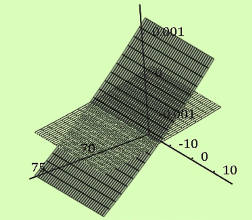
Kelemen Cs., Máté M. – Műszaki Tudományos Közlemények 14. (2021)                                            45

origin surface of the involute gear hob edges. In-         2. The helical involute surface
tense research interest in this direction has been          Equations of the helical involute surface will be
seen over the last two decades [6, 7, 8].                  given here using two different parametric forms:
  The involute worm is commonly obtained by a              the first is based on mathematical meshing, while
threading operation, using a pair of straight edged        the second uses the geometric and the motion pa-
threading cutters, where the flank meshing edges           rameters of the real cutting edge.
lie in two parallel planes that are tangential to the
basic cylinder. This arrangement could potential-          2.1. The theoretical involute helix surface
ly be a source of two types of error: the position of        The theoretical involute helix is meshed by an
the edge plain relative to the basic cylinder, and         involute curve of plane (y0 z0) which executes a
the edge profile angle. The latter is the summative        roto-translation about axis x0 of a helix pitch that
effect of the positioning and the manufacturing            equals max π. The parametric equations are written
errors. A third source of error is supposed to arise       considering the geometric dependences shown in
from the parallelism deviation of the turning pad          Figure 1. The form of equations differs from the
axis to the direction of the longitudinal motion.          classic one. Here the curve starts on the pitch cir-
  Although the modern high-power worm drive’s              cle, thereby omitting the unnecessary arc situated
bearing surfaces are ground, here exists another           between the basic and the dedendum circle.
possibility for fine cutting. This arises from the           From Figure 1 the following parametric equa-
incredibly large variety of high performance cut-          tions result:
ting inserts, able to realize surface roughness and
precision comparable with ground surfaces. Us-
ing them, the well-known expensive and environ-                                                        (1)
ment-damaging grinding can be substituted with              The interval of the parameter θ is obtained by
turning. Considering only the finishing operation,         setting the limits of the radius length:
cutting forces will not increase over an accept-
able limit, even in the case of hardened surface                                                           (2)
machining. Thus, the dimensions will be kept
between the limits of tolerance. All these can be            Figure 2 shows the profile of the involute worm
realized only if using modern machine-tools with           in a radial section.
increased rigidity.                                          Using the well-known dependences between the
  The arguments given before, justify the necessi-         normal and axial module [4], the helix parameter
ty for the modeling of manufacturing errors.               can be primed as follows

Figure 1. Definition of the involute curve in the case     Figure 2. Radial section of an involute worm.
       of an involute worm.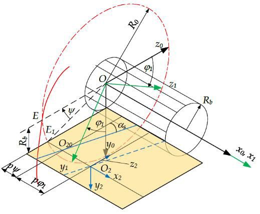
46                                               Kelemen Cs., Máté M. – Műszaki Tudományos Közlemények 14. (2021)

                                                  (3)   The correction depends on angular correction ψ
                                                        expressed as:
  Omitting the computation, the surface obtained                                                             (6)
by applying a roto-translation of parameter p to
the involute (1), results in the following paramet-       The correction is based on a geometric peculi-
ric equations:                                          arity presented below. The left tooth gap surface
                                                  (4)   (i.e. the right tooth surface) is meshed by the edge
                                                        situated under the axis x0, and it intersects the
                                                        pitch cylinder in O20.
                                                          The edge is at a distance Rb from the (x0 z0) plane.
                                                        Due to this, it must be rotated by the angle ψ about
2.2. The helical involute surface, meshed by            the axis Ox0 to force point O20 to overlap E.
     the cutting edge                                     The matrix form of the cutting edge related to
  The cutting-edge generated helical-involute par-      the frame (x2 y2 z2) linked to the cutter body is as
ametric equations are obtained by applying to the       follows:
cutting edges the same roto-translation of param-                                                            (7)
eter p given by (2), applied before. Cutting edges
are situated in two parallel planes, each of them
                                                         Moving the edge along the pitch helix of axis x
tangent to the basic cylinder. The mathematical
                                                        and parameter p discussed before, it will mesh a
form obtained here is of emphasized importance
                                                        helical surface described with the following par-
because it represents the errorless reference
                                                        ametric equations (here the calculus is omitted):
surface. It is compulsory to set the position of
the edges in such way that the surfaces meshed
by them include point E and its diametric oppo-
site. Both points are situated on axis z (Figure 3).
These points also fit the pitch circle.
  The profile angles are the angles comprised be-
tween the edges and a perpendicular to the worm                                                              (8)
axis [1, 7, 8]:
                                                  (5)   2.3. The comparison of the theoretical heli-
                                                             cal involute surfaces
  Because of the profile angle, a helical effect          The theoretically perfect, errorless helical sur-
occurs (Figure 3), In order to overlap the math-        faces are coincident. This can be mathematical-
ematical and the kinematic involute surfaces, a         ly proven by deducting a bijective dependence
translation of the edge along axis x is necessary.      (ϕ, θ)↔(ϕ1, u) between the independent parame-
                                                        ters of coordinate functions (4) and (8).
                                                          Equalizing the x-coordinates, results in
                                                                                                             (9)

                                                         By the other side, if equalizing the polar radii we
                                                        get:
                                                                                                            (10)

                                                         Considering the right side with the minus sign
                                                        and substituting expression (9) in the left side,
                                                        equation (10) takes the following form:
                                                                                                            (11)
                                                          The last equation can be considered an inter-
                                                        esting approach of the equivalence of the con-
                                                        sidered helical surface meshing procedures. The
Figure 3. The positioning of the cutting edge.          role of the parameter θ in expression (4) consists
Kelemen Cs., Máté M. – Műszaki Tudományos Közlemények 14. (2021)                                              47

in the generating of the involute curve as can
be observed from equations (1). On the other
hand, parameter ϕ1 from equation (8) expresses
the quantum of the rotational component of the                                                              (13)
helical generating motion. Despite the fact that                                                            (14)
the functional role of the mentioned parameters
differs, the correspondence can be accepted. In              The helical surface written with the expressions
the first case where the involute is used as gen-          (12)..(14), becomes a perfect helical involute sur-
erating curve, all surface points corresponding to         face only if parameter f = 0. The border positions
an arbitrary value of the rotation parameter are           of the real helical surface, for the maximum value
comprised in the same radial plane. In the second          of the setting error can be obtained from f Rb= Δh
case, where the generating curve is the cutting                                                          .
                                                           equivalent with the f- interval
edge, surface points having the same rotational
parameter value are situated on the edge, not in a
                                                           3.2. The parallelism error
common radial plane as before.
  On the other hand, condition (9) expresses the             The parallelism error is defined as the devia-
equality of the x-coordinates. Thus, the consid-           tion between the trajectory of the longitudinal
ered points are constrained to fit the same radial         feed motion and the rotation axis of the turning
plane. Furthermore, these points can overlap if,           machine, for a motion length of L = 1000 mm. In
and only if, expression (11) involving θ and ϕ1 is         this paper the deviation is particularized by con-
true.                                                      sidering the trajectory of the feed line included
  Conditions (9) and (10) involving surface par-           in the horizontal plane (x z). Thus, the trajectory
ametric equations (4) and (8) were numerically             line includes, with the axis, an angle β of magni-
computed. The simulation shows a difference of             tude tg β ≈ β = δp / 103. A δp = 100 μm parallelism
a 10–15 magnitude between the x, y ,z coordinates          deviation value occurs when the machine tool
computed with formulae (4) and (8).                        reaches its final wear state. This state leads to
                                                           β ≈ 1∙10–4 rad, namely 20.62 sexadecimal seconds.
3. The simulation of the manufacturing                       Admitting the described feed trajectory devia-
   errors                                                  tion, the last column of matrix M02 becomes:
  The manufacturing errors arise from the posi-
tioning of the cutter, the geometric errors of the
machine tool and the edge profile error. The ef-                                                            (15)
fect of each of them is separately studied because
they are independent statistical variables.
3.1. The center error of the cutter
                                                             The R3 subspace of the helical involute manifold
  The center error of the cutter can be defined as
                                                           results for –10–4 ≤ β ≤ 10–4 In this model the origin
the deviation of the distance between the rotation
                                                           of the worm’s frame is placed in the middle point
axis and the edge holding plane, from the basic
                                                           of its length. If the tool setting is computed consid-
radius value. To express this deviation a weight-
                                                           ering the limiting frontal plane of the worm, the
ing coefficient f is introduced. Applying it to the
                                                           frame’s origin must be translated here.
edge coordinate y expressed by matrix (7), val-
ue R_b is replaced with f Rb. If f > 0, the edge is        3.3. The profile error
pushed down, while for f < 0, it is raised up.              Profile error is defined as the maximum value
  The parametric coordinates result in the follow-         of the distance between the real edge point to the
ing matrix equation:                                       theoretical straight edge line (Figure 4). Profile
                                                    (12)   error can be perceived either as the deviation of a
                                                           concave or convex line from its tangent in the ref-
                                                           erence point, where the tangent is the theoretical
                                                           edge direction, or as a straight line whose profile
                                                           angle differs from the theoretical, but it intersects
                                                           the theoretical edge segment in the reference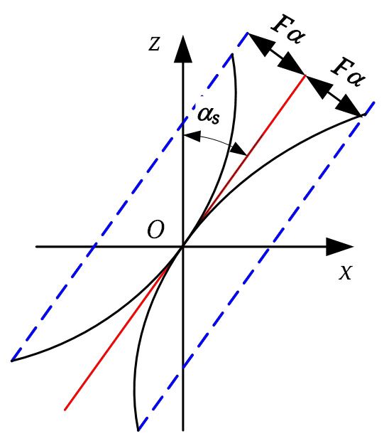
48 Kelemen Cs., Máté M. – Műszaki Tudományos Közlemények 14. (2021)
point. The reference point discussed before is al-
most the edgepoint acting on the pitch cylinder.
The profile error is assimilated with the quantity
Fα defined in gear precision standard and here it
is considered for an N8 precision class [9].
In the first case the error laden edge is expressed
using a polynomial of 3rd degree. The require-
ments imposed on this refer to the deviation that
must be smaller than the chosen Fα value, consid-
ering the useful length of edge 2.25 mn / cos αs. An-
other restriction imposed on the polynomial con-
sists in its tangency to the theoretical edge line, in
the origin (Figure 4).
The geometric constraints presented before re-
sult in at the most six algebraic equations, thus, Figure 4. The definition of the profile error
the simplest polynomial here is a polynomial of
3rd degree whose graphic crosses the origin; let’s Considering this together with expressions (16),
define it parametrically, using the following func- (18) and (19), a linear system with unknowns
tions: a1, a2, b1, b2 builds up. Its solution are the coeffi-
(16) cients of the 3rd degree polynomial.
The real helical surface equation results by using
(the free term of the polynomial is missing be- in matrix equation (12) the homogenous coordi-
cause in the origin u = 0.) nate vector .
The limits of u are (Figure 3):
4. Numerical evaluation
Numerical evaluation of the model presented
(17) before follows the steps emphasized below:
––writing the equations of the real helical surface
laden with the considered type of error, fol-
The profile error is measured perpendicular to lowed by the computing of surface point coordi-
the theoretical edge line. Accepting that the in- nates inside a fixed domain (u1, u2) × (ϕ1, ϕ2);
flexion point is missing (i.e. the real edge line is ––computing the coordinate of the pitch helix
either concave or convex), the coordinates of the point comprised in the plane (x0 z0);
endpoints for the convex edge can be written as: ––performing the translation of the coordinates
along the helix axis, given by ;
––computing the length of the normal segment be-
(18) tween the theoretical and the real surface– this
is the error.
The proofing was performed for an involute
worm of mn = 5 mm normal module, i = 1 number
In the same way the concave edge endpoint co-
of teeth, λ0 = 4°pith helix angle.
ordinates result in:
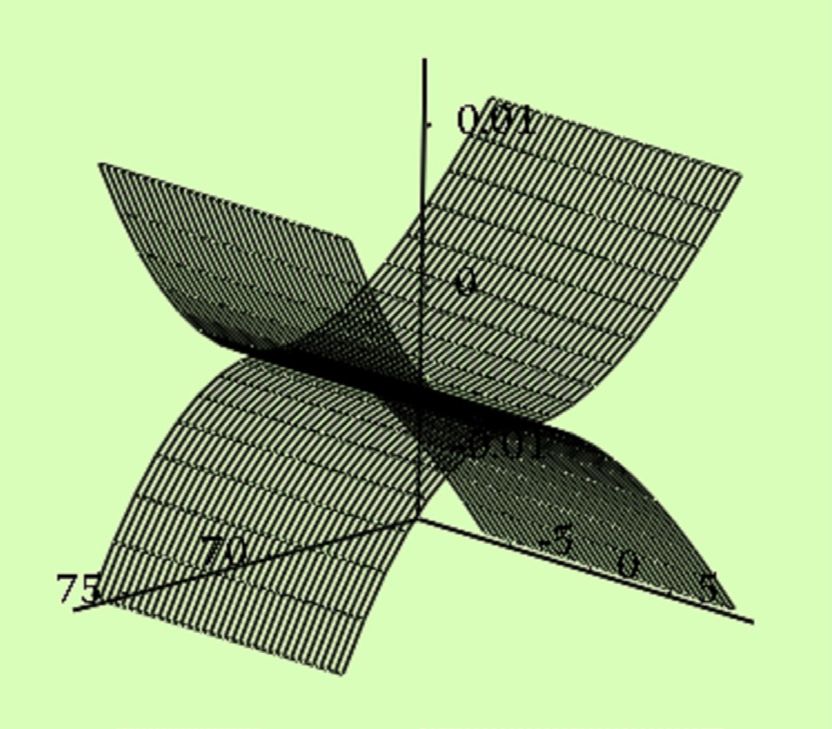
First the center error was analyzed, considering
the errors defined by f = 0.1 and f = 0.2. The distri-
bution of the errors is shown in Figure 5.
(19)
On the basis of figure 5 it can be stated that by
doubling the center error value the normal error
increases more than two times, thus the depend-
The condition of tangency in the origin becomes: ence is not linear. Although it must be empha-
sized that the maximal normal error value, for a
(20)
center error of f = 0.2 -re, meaning Δh = 0.2Rb =
2.698 mm reaches only Δnh = 1.631 μm. Inspecting
From condition (20) results obviously in:
the shape of the error distribution it can be stated
(21) that the error is positive signed on the addendum,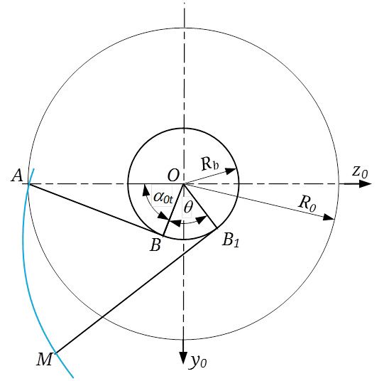
Kelemen Cs., Máté M. – Műszaki Tudományos Közlemények 14. (2021)                                            49

Figure 5. The distribution of the center error.            Figure 6. The normal error repartition caused by the
                                                                  edge profile error.

and negative on the dedendum cylinder. Positive              Results obtained by applying the parabolic mod-
error means that the real helical surface is larger        el are useful even in the case of a linear edge with
than the theoretical, including it, while negative         angular deviation. In this case the theoretical
error means that an undercut occurs.                       edge is placed in the middle of the tolerance field,
  Practical experience shows that the maximum              and thus, the maximum error occurs when the
center error value in the case of worm threading           real edge lies on the diagonal.
does not exceed 0.1 mm, thus normal error is lim-            It can be concluded that the previous model must
ited to a submicronic magnitude.                           set up for Fa / 2 value. The expected normal profile
  Starting from a N8 precision class and the corre-        error magnitude becomes Δnp ≈ 0.25 Fα = 7 μm.
sponding profile error value of Fα = 27 μm, edge             The cumulative error value is computed con-
profile error induced surface normal errors were           sidering the center and the profile errors as inde-
                                                           pendent statistical variables. The sign of the error
computed for the same worm. The repartition of
                                                           is here omitted; only absolute values are taken
the computed value is shown in Figure 6.
                                                           into consideration.
  The effect of the concave deviation of the cutting
                                                             Let us denote with ξ the statistical variable de-
edge results in the surface located below, while
                                                           fining the normal error caused by the center er-
the convex deviation in the surface located above.
                                                           ror, and with η the error caused by the edge pro-
It must be emphasized that the error value on the
                                                           file. The variance extends within the zero and the
pitch cylinder is zero. This proves the correctness        maximum error value, thus
of the computation and the model, while tangen-
cy of the theoretical and the error laden edge was                                                         (22)
imposed.
  In contrast to the center error causing normal            Admitting a reasonable approach, it can be sup-
error repartition, here the error keeps its sign.          posed that the average value of the cumulative
The absolute values shown an approximately par-            error is:
abolic evolution.
                                                                                                           (23)
  The cutting edge’s concave deviance produces a
real helical surface that includes the theoretical          In a same way a good approach of the standard
involute helical worm surface. Conversely, a con-          deviation can be considered the 1/6 part of the
vex edge deviance results in a real helical surface        variance [10]. Thus, the standard deviation of the
that undercuts the theoretical. The common enti-           cumulative error becomes:
ty of all three is the pitch helix.
  In this case, the maximum value of the normal                                                            (24)
error does not exceed Δnp ≈ 13 μm, which is only
half of the admissible edge profile deviation.
50 Kelemen Cs., Máté M. – Műszaki Tudományos Közlemények 14. (2021)
In the spite of the fact that the composition of The error of the threading kinematic chain was
two normally distributed statistical variables neglected because the axial extent of the worm
results in an exponential distribution [10], let will never exceed 6-8 integral pitches. On that
us consider ζ normal distributed. The differenc- length, the pitch errors of the leading screw, as
es can be neglected as well, as it was proven by well as the parallelism error influences are not
many industrial applications. The statistical com- relevant. It must be mentioned here that modern,
puting model of the machining allowances [11] is
numerical driven machine’s kinematic chains
built up admitting the same hypotheses.
present pitch error of micronic magnitude. .
Admitting these the maximum value of the cu-
mulative normal error becomes: References
(25) [1] Dudas I., Varga G., Banyai K.: Holonic manufactur-
ing system for production of different sophisticat-
5. Conclusions ed surfaces. Proceedings of the IASTED Interna-
tional Conference on Modelling, Simulation and
Mathematical models presented in this paper
Optimization (2004) 72–75.
can be used for the estimation of the expected
[2] Balajti Zs.: Examination and adjustment of the
manufacturing error value, in the case of involute bearing pattern in case of helicoid drive. 8th CIRP
worm threading, Conference on High Performance Cutting, Buda-
The presented method is notably important pest, Hungary, June 25-27. 2018. Procedia CIRP, 77
while having knowledge upon the geometric pre- (2018) 267–270.
cision of the manufacturing infrastructure. With [3] Balajti Zs., Dudás I.: The Monge Theorem and Its
this model it can be decided if a given involute Application in Engineering Practice. The Interna-
worm can or cannot be realized within the pre- tional Journal of Advanced Manufacturing Tech-
scribed limits of tolerance. nology. Article 9763, Springer, London (2016).
The worm error sources were supposed to have https://doi.org/10.1007/s00170-016-9763-1
originated from the center positioning error of [4] Dudas I.: The theory and practice of worm gear
the edge, the profile error of the cutting edge and drives. Penton Press, London, 2000.
[5] I Tsay C. B., Tseng J. T.: Undercutting and contact
the parallelism error of the machine tool. The last
characteristics of cylindrical gears with curviline-
was neglected, thus, the cumulative error was
ar shaped teeth generated by hobbing. Journal of
computed as the sum of the center and the profile
Mechanical Design, 128/3. (2006) 634–643.
errors. [6] Mohan L. V.: Geometrical aspects of double envel-
The center error and the profile error were con- oping worm gear drive. Mechanism and Machine
sidered as independent statistic variables. Theory, 44, (2009) 2053–2065.
The error was defined as the normal distance [7] Radzevich S. P.: A way to improve the accuracy of
between the real and the errorless involute helix hobbed involute gears. Journal of Mechanical de-
surfaces. sign, 129/10. (2007), 1076–1085.
In our perception, error is plus signed if the real https://doi.org/10.1115/1.2761919
surface covers the theoretical, and negative if un- [8] Radzevich S. P.: Investigation of the tooth geome-
dercuts it. try of a hob for manufacturing of involute gears
The computing of the normal error was realized (in Tool-in-Use References System). Journal of
within a synthetic geometric model that was not Manufacturing Science and Engineering, 129/4.
presented here. (2007), 750–759.
[9] KG Stock Gears: Gear Technical Data. 5.7 Precision
The numerical evaluation has proven that the
of Spur and Helical gears. Letöltés: 2021. 04. 06.
center error has the least impact on the cumu-
https://www.kggear.co.jp/en/wp-content/themes/
lative error, while its rate is only 11,69% of the
bizvektor-global-edition/pdf/5.7_Precision-of-
cumulative error– even in the case of considering Spur-and-Helical-gears_TechnicalData_KG-
exaggerated values of the tool center error. STOCKGEARS.pdf.
In conclusion it can be stated with a good ap- [10] Cseke V.: A valószínűségszámítás alapjai. Dacia
proximation that the involute worm manufac- Könyvkiadó, Kolozsvár, 1982.
turing cumulative error equals half of the profile [11] Drăghici G.: Tehnologia Construcțiilor de mașini.
error. E.D.P., Bukarest, 1985.You can also read