ALBANY TRANSMISSION LINE EXTENSION PROJECT - AEP Transmission

Page created by Ron Richards
 
CONTINUE READING
ALBANY TRANSMISSION LINE EXTENSION PROJECT - AEP Transmission
ALBANY
                               TRANSMISSION LINE EXTENSION PROJECT

WELCOME TO OUR VIRTUAL OPEN HOUSE
As a result of the COVID-19 pandemic and social distancing recommendations made by the Centers
for Disease Control and Prevention (CDC), AEP Ohio representatives invite you to attend this virtual
open house in order to minimize in-person contact. AEP Ohio remains committed to listening to your
concerns and answering your questions, but we are also committed to keeping our customers and
employees safe and healthy. We welcome your feedback via telephone and email as we strive to
make the most informed decisions possible.
ALBANY TRANSMISSION LINE EXTENSION PROJECT - AEP Transmission
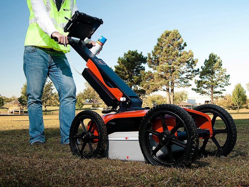
HOW THE SYSTEM WORKS

1) GENERATION STATIONS                   2) EHV TRANSMISSION                3) SUBSTATIONS
Utilities produce electricity at coal,   Extra-high Voltage electric        Substations direct the flow of
natural gas, nuclear, wind and           transmission lines are generally   electricity and either decrease or
hydroelectric power stations and         765 kilovolt (kV), 500 kV, and     increase voltage levels for transport.
then transport it long distances over    345 kV on AEP Ohio’s system.
transmission lines.
ALBANY TRANSMISSION LINE EXTENSION PROJECT - AEP Transmission
HOW THE SYSTEM WORKS

4) LOCAL TRANSMISSION                     5) SUBSTATION                         6) PRIMARY DISTRIBUTION
AEP Ohio typically uses 69 kV and         Substations transform 69 kV and       These main lines (also called circuits)
138 kV transmission lines to move         138 kV electricity into lower         connect substations to large parts of
power shorter distances - for example,    distribution level voltages such as   the community.
to different parts of a city or county.   34.5 kV, 12 kV, or 7.2 kV.
ALBANY TRANSMISSION LINE EXTENSION PROJECT - AEP Transmission
HOW THE SYSTEM WORKS

                                                                              TO USE AN ANALOGY, ELECTRIC
                                                                              TRANSMISSION IS SIMILAR TO OUR
                                                                              NATIONAL ROAD SYSTEM. THREE KINDS
                                                                              OF POWER LINES EXIST BETWEEN POWER
                                                                              PLANTS AND HOMES AND BUSINESSES:

                                                                              • Extra-high Voltage lines are like
7) LATERAL DISTRIBUTION                8) INDIVIDUAL SERVICE                   electrical interstate highways.
These smaller capacity lines deliver   Smaller transformers step down         • High-voltage local transmission lines are
electricity to neighborhoods and       voltage to levels customers can use.
                                                                               like four-lane roads.
other smaller groups of customers.     Individual residences typically use
                                                                              • Distribution lines are like two-lane roads
                                       120/240 volts.
                                                                               that eventually connect to your driveway.
ALBANY TRANSMISSION LINE EXTENSION PROJECT - AEP Transmission
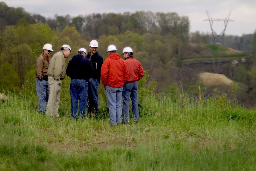
PROJECT NEED

WHY IS THE PROJECT IMPORTANT TO OUR COMMUNITY?

BUILDING THE NEW POWER LINE
• Provides an additional power source to improve electric service reliability
• Reduces the likelihood of larger, sustained community power outages
ALBANY TRANSMISSION LINE EXTENSION PROJECT - AEP Transmission
PROJECT SCHEDULE

                                          2021   2022                                                       2023
PROJECT ANNOUNCEMENT
March 2021

VIRTUAL OPEN HOUSE
March 2021

RIGHT-OF-WAY COMMUNICATIONS BEGIN
Spring 2021

FIELD SURVEYS AND ENGINEERING
Spring 2021

FILE LETTER OF NOTIFICATION WITH OPSB**
Fall 2021

ANTICIPATED OPSB** DECISION
Late 2021

CONSTRUCTION
Late 2021-Spring 2022

FACILITIES PLACED IN SERVICE
Spring 2022

RESTORATION ACTIVITIES COMPLETE
Summer 2022
                                                        *Timeline subject to change   **Ohio Power Siting Board
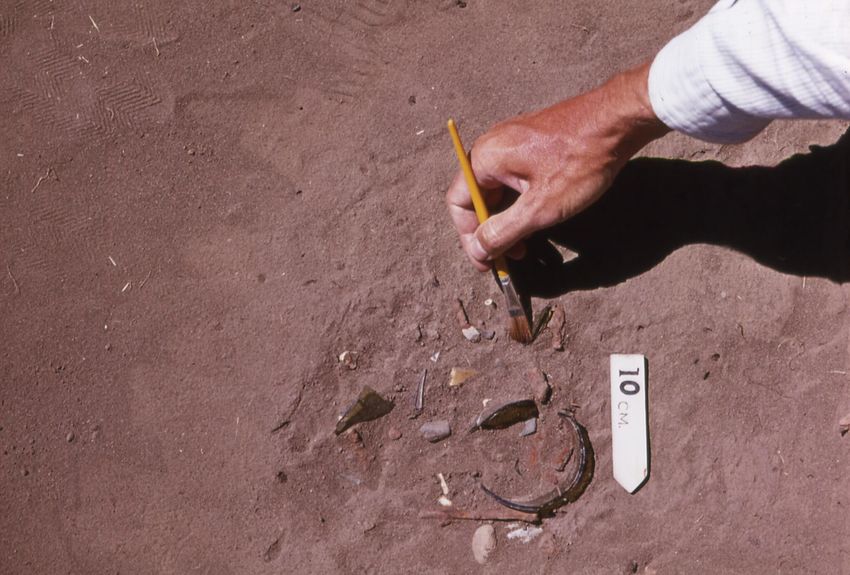
ALBANY TRANSMISSION LINE EXTENSION PROJECT - AEP Transmission
PROPOSED STRUCTURES

                                                                  The project involves the use of single,
                                                                  steel poles.

                                                                  Structure Height: Approx. 70-90 feet*
                                                                  Right-of-Way Width: Approx. 100 feet*
                                       Approximately
                                         70-90 feet

                       Approximately
                          100 feet

*Exact structure, height and right-of-way requirements may vary
ALBANY TRANSMISSION LINE EXTENSION PROJECT - AEP Transmission
STRUCTURE COMPARISON
Typical structure heights are based upon voltage and configuration. Structures are not to scale but are shown in proportion to each other. Actual heights will vary depending on terrain.

                                                                                                                                                                                                                                                                     28’
                                                                                                                                                                                                                                                                                                                               28’

                                                                                                               Typical Height - 100’ to 120’
                                                                                                                                                                                                 34’

                                                   Typical Height - 70’ to 90’

                                                                                                                                                                                                                                            Typical Height - 99’

                                                                                                                                                                                                                                                                                                      Typical Height - 90’
                                                                                                                                                                Typical Height - 70’
                                                                      50’ to 65’ ROW                                                            100’ ROW                                   100’ ROW                                                                100’ ROW                                                  100’ ROW
                                                       69KV                                                       138KV                                                                  138KV                                           138KV                                                        138KV
                                                   SINGLE CIRCUIT                                              DOUBLE CIRCUIT                                                          SINGLE CIRCUIT                                   DOUBLE CIRCUIT                                                SINGLE CIRCUIT
                                                     STEEL POLE                                                  STEEL POLE                                                              STEEL POLE                                       STEEL POLE                                                    STEEL POLE

                                                                                                                                                     59’

                                                                                                                                                                                                                             133’

                                                                                                                                                                                                                                                                                                                                        132’
                                          56’
                                                                                       Typical Height - 172’

                                                                                                                                                                                             Typical Height - 138’

                                                                                                                                                                                                                                                                              Typical Height - 127’
            Typical Height - 110’

                                        100’ ROW                                                                                                  150’ ROW                                                                 200’ ROW                                                                                                  200’ ROW

                                        138KV                                                                                                    345KV                                                                    765KV                                                                                                  765KV
                                    SINGLE CIRCUIT                                                                                             DOUBLE CIRCUIT                                                              GUYEDV                                                                                           SINGLE CIRCUIT TOWER
                                        TOWER                                                                                                     TOWER                                                              SINGLE CIRCUIT TOWER
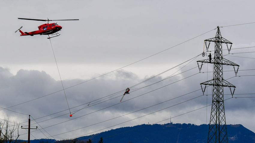
ALBANY TRANSMISSION LINE EXTENSION PROJECT - AEP Transmission
RIGHTOFWAY

AEP OHIO HAS TWO KEY PHILOSOPHIES THAT PERTAIN
TO POWER LINE RIGHTSOFWAY:

  1                                    2
      Routes should cause the least        Property owners should be fairly
      possible disturbance to people       compensated for any land rights
      and the environment.                 that must be acquired.
ALBANY TRANSMISSION LINE EXTENSION PROJECT - AEP Transmission
RIGHTOFWAY

AEP Ohio studies the land and proposes routes that reduce impacts on property owners.
AEP Ohio reaches out to landowners in the following ways:

TO GAIN RIGHT-OF-ENTRY TO BEGIN:                              TO SECURE RIGHT-OF-WAY AND COMMUNICATE:
  • Environmental assessments                                   • Landowner compensation
  • Appraisal work                                              • Terms and conditions of easement
  • Land surveying, soil boring and other field activities      • Width of the right-of-way
  • Cultural and historic resource reviews

TO OUTLINE AEP OHIO’S CONSTRUCTION PROCESS WITH A SPECIFIC FOCUS ON:
  • Property restoration
  • Damage mitigation as appropriate
FIELD ACTIVITIES

GROUND PENETRATING RADAR                                                                             HELICOPTER
Ground Penetrating Radar (GPR) helps identify the location of underground utilities. A device that   Challenging terrain or other restrictions/obstructions can make accessing certain parts of a project
looks similar to a lawnmower, and is nondestructive to the soil, uses radio frequencies to detect    area difficult. In these locations, crews use helicopters to install structures, string conductors, per
objects below the ground's surface. Maps and images are created from the data.                       form line work and maintain electric facilities. Company representatives work with local media out
                                                                                                     lets to communicate these activities to the public.

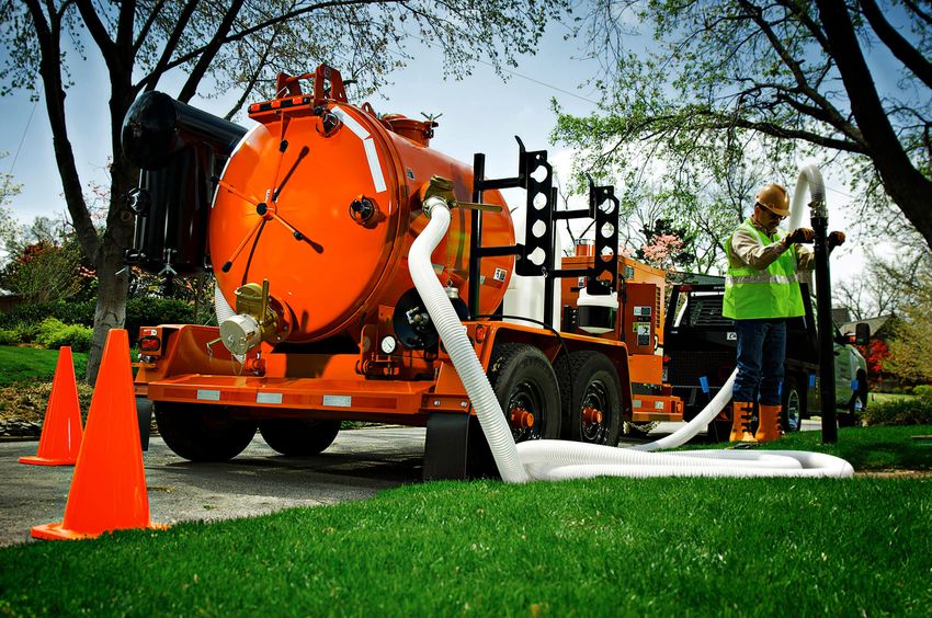
HYDRO EXCAVATION                                                                                     LIDAR
Crews use hydro excavation (hydrovac) in areas where many underground utilities are located near     LiDAR (Light Detection and Ranging) uses laser pulses to measure the distance of an object to the
each other. This process involves using pressurized water to break down soil to expose under-        source. The data points result in digital 3D maps for accurate design and engineering. LiDAR sur-
ground utilities. Afterward, crews backfill the area. The process helps prevent damage to under-     veying crews use mobile (car or aerial vehicle) or static (tripod) equipment.
ground infrastructure while gathering important information.
FIELD ACTIVITIES

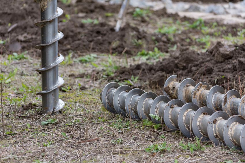
SOIL BORINGS                                                                                             CULTURAL RESOURCE SURVEY
Field crews use a drill to bring up soil samples and then backfill the holes. Testing the core sam-      Field crews walk the area and conduct multiple excavation tests to identify historical and archaeo
ples helps determine soil conditions in the area. Soil conditions and types can affect structure loca-   logical artifacts. Landowners also provide information about their property to survey crews.
tion and foundation design.

ENVIRONMENTAL SURVEY                                                                                     UNMANNED AERIAL VEHICLES (DRONES)
Surveyors collect information about the habitats and physical attributes of the project area. They       Unmanned aerial vehicles (UAVs), or drones, perform aerial inspections and safely gather data and
also look for ecological concerns like wetlands, flood plains and forests. This process can help pro-    detailed images of electric facilities. Company employees and vendors comply with all commercial
tect endangered species, such as the Indiana Bat and American Burying Beetle.                            Federal Aviation Administration (FAA) guidelines. Company representatives work with local media
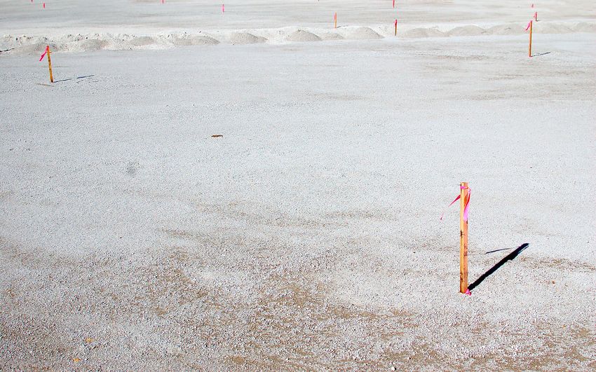
                                                                                                         outlets to communicate these activities to the public.
FIELD ACTIVITIES

STAKING                                                                                               FIELD SURVEY
• Field crews use staking to mark the project area, identify utility equipment and pinpoint future    • Field survey crews help determine an appropriate route for a new transmission line by identifying
  structure locations. This process essentially transfers engineering and construction plans to the     constraints within the project area.
  field.                                                                                              • Engineers conduct extensive studies of the terrain and soil to determine what types of structures
• Right-of-way crews use staking to identify parcel boundaries, easement boundaries and other           and foundations are most suitable. They also gather information to create digital 3D maps of the
  utility locations within the company’s rights-of-way.                                                 project area to help engineer and design the project.
• Environmental crews use staking to identify wetlands or other environmentally sensitive areas.
VEGETATION MANAGEMENT

                                                                  THE GOALS OF AEP OHIO’S VEGETATION MANAGEMENT
                                                                  PROGRAM ARE TO:

                                                                  • Protect our system and minimize outages
                                                                  • Minimize any adverse environmental impacts
                                                                  • Ensure compliance with all applicable laws and regulations
                                                                  • Perform our work as safely as possible
                                                                  • Maintain a positive relationship with land owners and the public

WHAT IS VEGETATION MANAGEMENT?
The practice of controlling the growth of trees and other woody
stemmed vegetation in line corridors and around substations,
while maintaining respect for the environment.

WHY IS IT DONE?
         To minimize power outages caused by trees and
         other plants coming into contact with power lines.
CONSTRUCTION PROCESS

               AEP Ohio understands the work related to transmission
               grid improvements can sometimes be an inconvenience.
               That's why the company makes every effort during the
               construction process to respect the environment and our
               neighbors, while working safely to ensure reliable
               electric service.

               AEP Ohio plans to work with individual property owners
               throughout the construction process. Team members
               provide details of upcoming work and listen to customer
               feedback. If damages occur during the construction
               process, the company works to restore property as close to
               its original state as possible.
ROUTING PROCESS

AEP Ohio implements a
comprehensive siting process               Substation A                                Substation A

that takes land use, the
environment, public input and
engineering guidelines into
account to develop a
                                                                 Substation B                                 Substation B
transmission line route. The
information below illustrates
each stage of the routing process.   1) STUDY AREA                              2) DATA GATHERING
                                     AEP Ohio develops a study area for the     Data is gathered for the defined study
                                     project that incorporates both end         area including environmental, land use,
                                     points of the power line and the area      historic and cultural resources, existing
                                     between.                                   infrastructure and sensitive areas.
ROUTING PROCESS

      Substation A                                    Substation A                                                                                                             Substation A
                                                  1                                                                                                                        1
                                                               2
                                                                                       7
                                                           3                                                                                                                     3
                                                                        6
                                              4                                                                                                                        4
                                                                                                                               19
                                                      5                               13                                                                                                             13
                                                                                                      14                                                                                                        14
                                                                                                                      18                                                                                                     18
                                                  8                                                  16 17                                                                                                     16
                                                                                 15                                                      20                                                     15
                                              9                    11                                                                                                  9              11
                                                          10
                                                               12                                                                                                                    12
                                                                            21                                  26        27                                                               21                                 27
                                                                                                           25                                                                                                        25
                                                                                           22                                                               37
                                                                                      23                                  32                                                                         23
                                                                                                24         28 30     31                                                                                   24         28 30
                                                                                                                                          36                                                                                       36
                                                                                                            29                      35
                                                                                                                          34                                                                                                  34
                                                                                                                                                     42
                                                                                                                                         38
                                                                                                           33                                  40   41                                                                                  40
                                                                                                                                         39                                                                                        39

                           Substation B                                                                                                             Substation B                                                                             Substation B

3) CONCEPTUAL ROUTES                      4) STUDY SEGMENTS                                                                                                        5) REFINED STUDY SEGMENTS
The routing team uses this information    Conceptual routes are broken up                                                                                          As more information is gathered, the
to develop conceptual routes adhering     into study segments. Where two or                                                                                        study segments are refined. Some
to a series of general routing and        more potential study segments                                                                                            study segments are eliminated or
technical guidelines.                     intersect, a node is created, and                                                                                        modified, leaving the refined study
                                          between two nodes, a link is formed.                                                                                     segments for further consideration.
                                          Together, the network formed by
                                          these links is referred to as potential
                                          study segments.
ROUTING PROCESS
                                                   Substation A
        Alternative         Alternative
        Route A             Route B

                                                                  Proposed
                                                                  Route

        Alternative         Alternative
        Route C             Route D

                                                                             Substation B

                                          7) PROPOSED ROUTE

6) ALTERNATIVE ROUTES                     Alternative routes are assessed and a proposed route is
                                          chosen. The proposed route minimizes impact to the
After public input is gathered, study
                                          community and environment, while considering cost, line
segments are further refined and
                                          length and design requirements.
evaluated. The most suitable
segments are selected and assembled
into alternative route options.
PROJECT MAPS

OVERVIEW MAP
Step 1: Below is an Overview Map that displays the entire project area. Please use the Overview Map to find the
general location of your property.

Overview Map (PDF)

DETAILED MAPS
Step 2: Each outlined area on the Overview Map represents a single, numbered Map Page that shows that section in
greater detail. Visit the appropriate Map Page below for your area.

Detailed Map 1 (PDF)                          Detailed Map 7 (PDF)
Detailed Map 2 (PDF)                          Detailed Map 8 (PDF)
Detailed Map 3 (PDF)                          Detailed Map 9 (PDF)
Detailed Map 4 (PDF)
Detailed Map 5 (PDF)
Detailed Map 6 (PDF)
ALBANY
 TRANSMISSION LINE EXTENSION PROJECT

THANK YOU!
Thank you for visiting the project virtual open house. For more information and project
updates please visit the project website, or contact us with any additional questions.
You can also read