ACCELSTOR NEOSAPPHIRE AFA BEST PRACTICES GUIDE FOR VMWARE VSPHERE
←
→
Page content transcription
If your browser does not render page correctly, please read the page content below
Best Practices

   AccelStor NeoSapphire AFA

   Best Practices Guide for VMware vSphere
   March 2019

   The information contained herein is subject to change without notice.
   Their respective owners own all trademarks and trade names.

Copyright © 2019 AccelStor Ltd. All rights reserved                        1
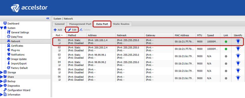
Table of Contents
Introduction ....................................................................................................................................... 4
Intended Audience ............................................................................................................................. 4
Systems Infrastructure........................................................................................................................ 5
    Reference topology.....................................................................................................................................5
        Reference Hardware. ......................................................................................................................................................... 6
    SAN Design .................................................................................................................................................6
        Fibre Channel Zoning ......................................................................................................................................................... 7
        Jumbo Frames in the SAN .................................................................................................................................................. 7
NeoSapphire AFA Configuration ......................................................................................................... 8
    iSCSI Connectivity .......................................................................................................................................8
        Network Configuration ...................................................................................................................................................... 8
        Volume Creation ................................................................................................................................................................ 9
        iSCSI Targets .................................................................................................................................................................... 11
    Fibre Channel Connectivity........................................................................................................................ 13
        Fibre Channel LUNs ......................................................................................................................................................... 13
VMware ESXi Host Configuration ...................................................................................................... 16
    Essential Configurations for iSCSI Environments ........................................................................................ 16
        Configuring the Software iSCSI Adapter .......................................................................................................................... 16
        Creating a vSwitch ........................................................................................................................................................... 17
        Adding Physical Uplinks ................................................................................................................................................... 17
        NIC Teaming and Failover Policy...................................................................................................................................... 18
    Connecting the NeoSapphire AFA to the ESXi Host ..................................................................................... 20
        Bind iSCSI and VMkernel Adapters .................................................................................................................................. 20
        Dynamic Discovery for iSCSI ............................................................................................................................................ 21
        Verifying Paths and Devices............................................................................................................................................. 21
    VMware ESXi Multipathing ....................................................................................................................... 22
        Change the Path Selection Policy to Round Robin .......................................................................................................... 23
        Round Robin I/O Operations Limit .................................................................................................................................. 24
        SATP Rule for Round Robin Policy ................................................................................................................................... 25
    ESXi Advanced System Settings ................................................................................................................. 25
        Disk.MaxIOSize ................................................................................................................................................................ 25
        Set Login Timeout to a Larger Value ................................................................................................................................ 27
        Disable DelayedAck ......................................................................................................................................................... 29
    VAAI Integration with AccelStor AFA ......................................................................................................... 30
        Checking VAAI Support .................................................................................................................................................... 30
        Enabling and disabling VAAI ............................................................................................................................................ 31
Datastore Management ................................................................................................................... 32

Copyright © 2019 AccelStor Ltd. All rights reserved                                                                                                                                2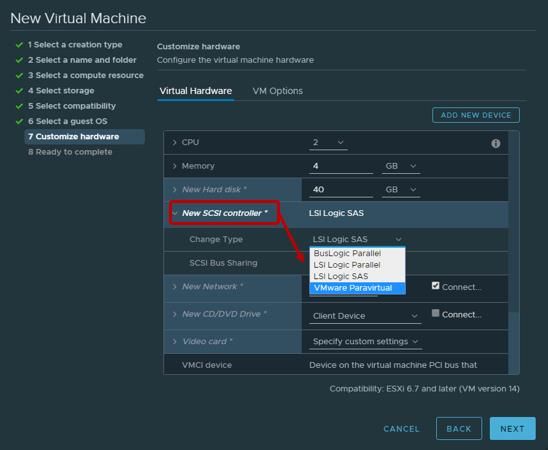
Adding Datastores .................................................................................................................................... 32
    Volume count ........................................................................................................................................... 32
    VMs per Datastore.................................................................................................................................... 33
    AccelStor Capacity Optimization ............................................................................................................... 33
    Datastore Performance Considerations ..................................................................................................... 34
    Deleting Datastores and Volumes ............................................................................................................. 35
Virtual Machine Configuration ......................................................................................................... 38
    Virtual Machine compatibility ................................................................................................................... 38
    General Hardware Settings ....................................................................................................................... 38
    Virtual Disk Type....................................................................................................................................... 39
    Virtual Disk Limit – IOPs ............................................................................................................................ 40
    Virtual SCSI Adapter.................................................................................................................................. 40
    VMware Tools .......................................................................................................................................... 41
Queue Depths .................................................................................................................................. 43
    Queue Depths on NeoSapphire AFA .......................................................................................................... 43
    Queue Depths on ESXi hosts...................................................................................................................... 44
        HBA Device ...................................................................................................................................................................... 44
        No of outstanding IOs with competing worlds ................................................................................................................ 44
    Queue Depths on the VM and Guest-OS .................................................................................................... 45
    Queue Depth Limits Examples ................................................................................................................... 45
Space Reclamation ........................................................................................................................... 47
    VMFS Datastore Reclamation .................................................................................................................... 47
        Settings Through Latest vSphere Versions ...................................................................................................................... 48
        Manual Space Reclamation ............................................................................................................................................. 49
    Guest-OS Reclamation .............................................................................................................................. 50
        Enable VMFS3.EnableBlockDelete ................................................................................................................................... 50
        Reclaim Space with Windows OS..................................................................................................................................... 51
        Reclaim Space with Linux OS ........................................................................................................................................... 53
Appendix .......................................................................................................................................... 54
    About PowerCLI ........................................................................................................................................ 54
References ....................................................................................................................................... 54
Version History ................................................................................................................................. 54

Copyright © 2019 AccelStor Ltd. All rights reserved                                                                                                                               3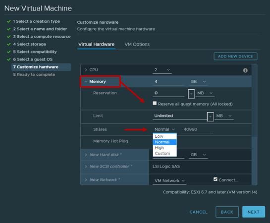
Introduction
   This document explains how to configure and connect an AccelStor NeoSapphire AFA to VMware vSphere
   hosts. It also provides design and implementation recommendations on network, performance, and
   management.

   This guide is based on the latest current version of VMware vSphere, which at the moment of writing this
   guide is ESXi 6.7 U1. The guide also covers prior versions of VMware ESXi for some of the most important
   settings. Earlier versions of ESXi may require a different workflow.

   The most important best practice when working with VMware vSphere hosts, is to keep the entire vSphere
   environment updated and patched with the latest releases. VMware regularly includes new features to
   improve functionally and resolutions to known bugs.

   Many references on this document are taken directly from VMware vSphere Docs. Follow VMware Best
   Practices to complement the information detailed here.

Intended Audience
   This document is prepared by AccelStor to assist customers in the configuration of the AccelStor NeoSapphire
   AFA models with VMware vSphere. Readers of this document are suggested to have:
        •    Essential network configurations knowledge
        •    Basic knowledge with iSCSI and Fibre Channel storage concept
        •    Basic knowledge with VMware vSphere client interface.

   For AccelStor partners who require additional assistance with AccelStor AFA products, please contact
   AccelStor’s Technical Support for more details.

Copyright © 2019 AccelStor Ltd. All rights reserved                                                       4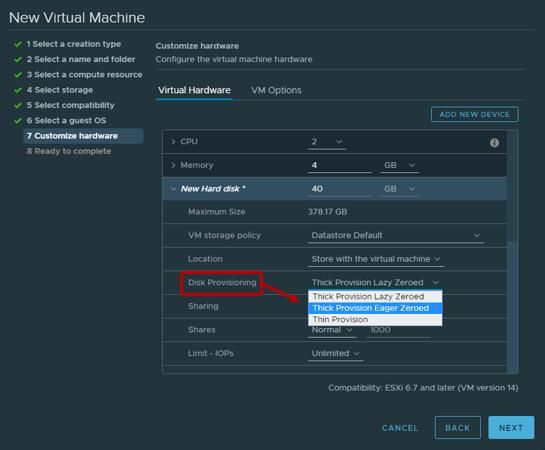
Systems Infrastructure
This section shows the essential and the minimum recommended physical topology to configure a vSphere
environment with AccelStor NeoSapphire AFAs.
The configuration presented in this document applies for both protocols Fibre Channel and iSCSI. For more
details about the system configuration and protocols, see the respective user manual of each model.
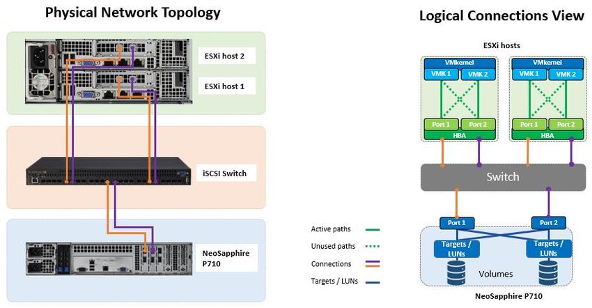
Reference topology
On this best practice document, two out of eight nodes (host) of a Supermicro SYS-F618R2-R72+ are used with
the AccelStor NeoSapphire P710 model. An iSCSI switch is used as a reference for the SAN fabric.
Note: For simplicity, the following illustration shows a P710 (single node) with a single SAN switch/fabric
configuration.
The above diagram illustrates a physical and logical view of a general (reference) topology. This diagram is a
reference for deploying an AccelStor NeoSapphire P710 (single node system) with dual ports connected to
two ESXi hosts with dual-port each. For High Availability models, isn’t necessary to do extra configuration
from the NeoSapphire Web-GUI, but the number of physical ports and paths will increase. To ensure that I/Os
are load-balanced across all storage array paths, distribute the paths to the volumes among all the storage
nodes/ports to provide optimal load-balancing.
Note: If the number of data ports increases, the complexity of the topology (above) will increase, and the
obtained result may vary according to the changes in the configurations.
Copyright © 2019 AccelStor Ltd. All rights reserved 5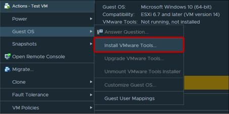
Reference Hardware.
   During the creation of this best practices document, the following hardware was used.

   Storage:
       •    NeoSapphire Model:        P710
       •    Image Version:            2.2.0
       •    SSD Configuration:        x24
       •    Data services:            Enabled

   Host Servers x2 (each host):
       •    Hypervisor:               VMware ESXi, 6.7.0, 10302608
       •    CPU:                      E5-2630 v4 @ 2.20GHz
       •    Memory:                   256 GB
       •    HBA:                      Intel E82599EB 10-Gigabit SFI/SFP+

SAN Design
   This section outlines the best practices for a proper SAN design with AccelStor NeoSapphire AFA and VMware
   ESXi hosts.

   The main components of the SAN are ESXi hosts with Host Bus Adapters (HBAs), SAN switches to route storage
   traffic, and the Storage Processors (SPs) or storage nodes.

   To achieve better performance between ESXi servers and NeoSapphire AFAs, follow these guidelines:
        •     Use at least two HBAs on the ESXi servers.
        •     Do not connect the ESXi hosts to the NeoSapphire AFA directly. This connection is possible but will
              cause performance constraints. For maximum performance, at least one SAN switch is required to
              connect the NeoSapphire AFA to an ESXi server.
        •     Use two SAN switches to provide fully redundant paths.

Copyright © 2019 AccelStor Ltd. All rights reserved                                                           6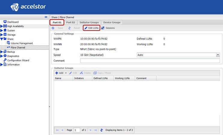
Fibre Channel Zoning
   To prevent ESXi hosts accessing the storage array (not designated to that ESXi host,) the SAN uses zoning.
   Zones are commonly used for permission management and define which HBAs can connect to which storage
   array node/ports. Devices outside a zone are not visible to the devices inside the zone.

   When using Fibre Channel, the best practice is to create zones for individual initiator ports (single host port)
   with one or more storage target ports.

 Jumbo Frames in the SAN
   Network devices use Maximum Transmission Unit (MTU) to manage to the largest size packet or frame that
   can be sent in through the network. The default MTU value on many devices is 1500 Bytes. Jumbo Frames are
   Ethernet frames with the size that exceeds 1500 Bytes; this increase in the MTU is often used to offer fewer
   collisions and less overhead, which contributes to high-performance data transmission over the network.

   If you use iSCSI for traffic management, the best practice from VMware for All-Flash Arrays and AccelStor
   NeoSapphire AFAs after internal lab tests is not to alter Jumbo Frames. The recommendation to avoid Jumbo
   Frames is for providing marginal performance gains while adding extra complexity due to the configuration
   required of every individual entity in the network environment.

   There are situations where enabling Jumbo Frames is adequate, and the following considerations apply:
       •   AccelStor Supports Jumbo Frames, and it allows Jumbo Frames with the MTU up to 9000 Bytes.
       •   ESXi allows Jumbo Frames with the MTU up to 9000 Bytes.
       •   Jumbo Frames must be supported end-to-end, on all the systems infrastructure. Targets, iSCSI Switch,
           and Initiators.
       •   Check with your iSCSI switch vendor to ensure it supports Jumbo Frames.

Copyright © 2019 AccelStor Ltd. All rights reserved                                                            7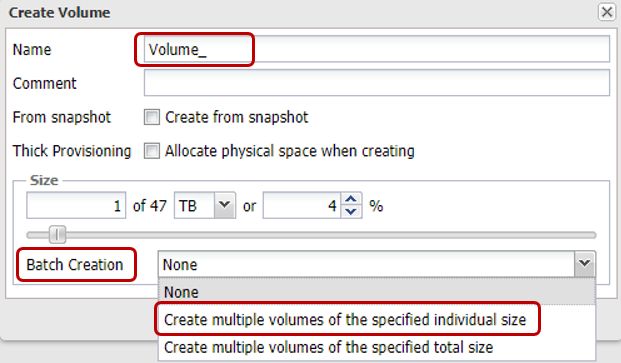
NeoSapphire AFA Configuration
   This section presents the basics and required storage configurations to present the NeoSapphire storage
   volumes to the ESXi Hosts. For the advanced and additional configurations on the NeoSapphire AFA, refer to
   the NeoSapphire User Manual.

   The AccelStor NeoSapphire AFA supports both FC and iSCSI protocols. When configuring and presenting the
   storage volumes, only one of these options will be available, depending on the selected model. The entire
   network environment solution should use the same protocol.

     To enable the maximum performance of the NeoSapphire AFA, you must use all the available
     physical (iSCSI or FC) ports!

iSCSI Connectivity
   Out-of-the-box, you only need to configure on the NeoSapphire AFA the network connectivity, then create
   storage volumes and present them to the ESXi Hosts. There is no need to do extra configuration, sizing, and
   calculations such as RAID and cache. AccelStor NeoSapphire AFA is a pre-configured system.

 Network Configuration
   The system requires the configuration of the Data Ports to communicate to the external network and later to
   the ESXi servers.

   Data Ports Configuration:
       1. Access to the AccelStor web-GUI home page
       2. Go to System > Networks.
       3. Click the Data Port tab.
       4. Select one of the data ports (Port 1 in the example).
       5. Click Edit.

Copyright © 2019 AccelStor Ltd. All rights reserved                                                          8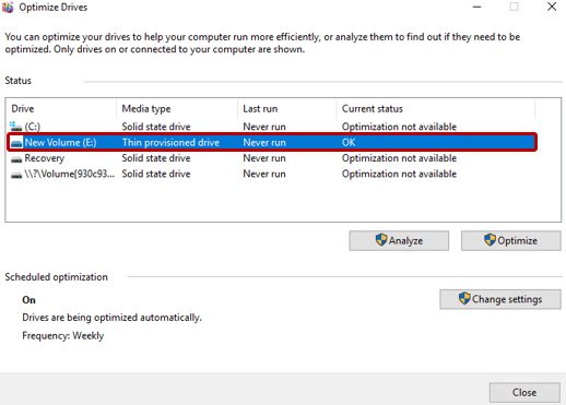
6. At IPv4 Method, select Static.
       7. Input Network configuration. Address, Netmask and Gateway.
       8. Under Advanced Settings, change MTU to 9000 to use Jumbo Frames if you decided to use it,
            otherwise leave the default 1500.

   Note: If you have decided to use Jumbo Frames, you must also consider the best practices in the Jumbo
   Frames in the SAN (For iSCSI) section.

       9. Click Save.
       10. Repeat to all available data ports.

 Volume Creation
   The volume (or LUN) is the most important unit of the storage system. Due to AccelStor AFA is a pre-
   configured system, there is no need to do prior configurations to start creating volumes.

   Note: For NeoSapphire AFAs iSCSI models, also, is possible to create Shared Folders using NFS or CIFS/SMB
   protocols. This document is limited to the creation of “block-level storage” volumes; Shared Folders are out of
   its scope.

   Volumes are created in a Thin-Provisioning format. Thin-Provisioning is enabled by default, to check its
   configuration see instructions below.

   Checking Thin-Provisioning
       1. Access to the AccelStor web-GUI home page
       2. Go to Storage > Drive.
       3. Click the Disk Array tab.
       4. Make sure that Enable Thin Provisioning is checked.

Copyright © 2019 AccelStor Ltd. All rights reserved                                                           9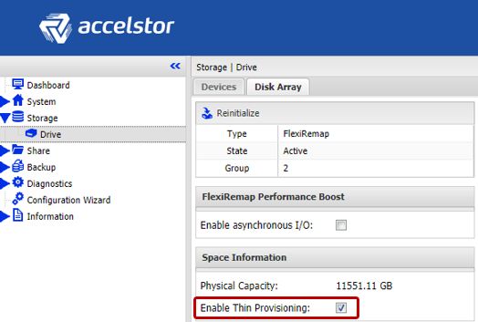
Volume Creation:
       1. Access to the AccelStor web-GUI home page
       2. Go to Share > Volume Management.
       3. Click the Volume Management tab.
       4. Click Add.

   Note: For multiple volumes scenarios, use Batch Creation. This option will allow you to create all the volumes
   at once quickly.

       5. Input a volume naming pattern.
       6. Select volume size.
       7. From Batch Creation, select an option that suits you best.
       8. After selecting Batch Creation, the Count option will let you add up to 24 volumes.
       9. Click Save.

Copyright © 2019 AccelStor Ltd. All rights reserved                                                         10
iSCSI Targets
You need to create iSCSI targets to present the volumes to the available storage ports. Each target will
establish the connection to the ESXi servers through iSCSI sessions.
Add Target:
1. Access to the AccelStor web-GUI home page.
2. Go to Share > iSCSI.
3. Click the Target tab.
4. Click Add.
5. From the General tab:
• Input an Identifier for the targets.
• Select Batch Creation to quickly create multiple targets. Select an appropriate option for your
configuration.
• After selecting Batch Creation, the Count option will let you add up to 24 targets.
Copyright © 2019 AccelStor Ltd. All rights reserved 11AccelStor recommends adding at least eight targets per associated volume. This configuration is
to guarantee the performance per volume and for path redundancy.
Note: Contact with the AccelStor Support Team for more information about other possible
configurations.
6. From the Portals tab, associate all the available (in use) storage ports that are connected to SAN.
7. From the LUN tab, click Add.
8. Assign LUN IDs to each created Volume. Select Bach Selection if you have the same name prefix in
your volumes.
Copyright © 2019 AccelStor Ltd. All rights reserved 129. Click Save and then Apply.
Note: From the ACL tab, it is possible to allow and deny volume access to the given ESXi hosts. For more
information about ACL, refer to the NeoSapphire User Manual.
Fibre Channel Connectivity
When NeoSapphire Fibre Channel model is used, the initial configuration is minimized only to volume creation
and mapping. No network configuration needs to be done for data traffic, just connecting the Fibre Channel
with the available Fibre Channel ports in the AFA.
To create volumes in the NeoSapphire Fibre Channel models, follow the same steps under the iSCSI models,
Volume Creation section.
Fibre Channel LUNs
You need to add “LUNs” to the storage volumes and present them to each available FC storage port. This
process is going to create a one-to-one relationship with all ESXi hosts in the SAN Network.
Add/Edit LUNs:
1. Access to the AccelStor web-GUI home page
2. Go to Share > Fibre Channel.
3. Click the Port 01 tab.
4. Click Edit LUNs.
Copyright © 2019 AccelStor Ltd. All rights reserved 1310. From the Edit LUNs window, click Add.
11. From the Volume Names drop list, select the desired volume.
12. Click Save.
13. Repeat steps 3 to 12 for all available Fibre Channel ports and all available volumes.
Note: It is possible to group ESXi hosts into Initiator Groups to prevent given ESXi hosts to access the storage
volumes. An Initiator Group is a collection of Fibre Channel WWNs initiators that refers to a physical
host. A NeoSapphire Initiator Group has a one to one relationship with an ESXi host. Every active
Copyright © 2019 AccelStor Ltd. All rights reserved 14initiator for a given ESXi host should be added to the respective NeoSapphire Initiator Group. For more information about Initiator Groups, refer to the NeoSapphire User Manual. Copyright © 2019 AccelStor Ltd. All rights reserved 15
VMware ESXi Host Configuration
   This section highlights the recommended configuration and best practices on the ESXi hosts before and after
   establishing the connection with the NeoSapphire AFA.

Essential Configurations for iSCSI Environments
   When iSCSI is used for data traffic, there are some prerequisites to configure on the ESXi host before applying
   advanced configurations and best practices. These prerequisites are listed in this section as additional
   guidance. For a complete configuration, VMware vSphere Documentations are referenced.

   The prerequisites for iSCSI are:
       •    Configuring the Software iSCSI Adapter.
       •    Creating a vSwitch
       •    Adding Physical Uplinks
       •    NIC Teaming and Failover Policy

 Configuring the Software iSCSI Adapter
   With the software-based iSCSI implementation, you can use standard NICs to connect the ESXi host to a
   remote (AFA) iSCSI target over the IP network.

   Add Software Adapter
       1. Navigate to the host.
       2. Click the Configure tab.
       3. Under Storage, click Storage Adapters, and click Add Software Adapter.
       4. Select Add Software iSCSI Adapter and click OK.

       5. The software iSCSI adapter is enabled under the name vmhba# (Vmhba64 in this example).

   For more information, see Activate or Disable the Software iSCSI Adapter

Copyright © 2019 AccelStor Ltd. All rights reserved                                                           16
Creating a vSwitch
In the VMware Host Client, you can add a virtual switch (vSwitch) to provide network connectivity to the ESXi
host that you are managing, to the virtual machines on that host and to handle VMkernel traffic. Also, to
manage the iSCSI storage, you need to create a dedicated switch in each ESXi host.
In this example, a Standard Virtual Switch is used. To add a Standard Virtual Switch, see Add a Standard Virtual
Switch in the VMware Host Client
Recommendations:
• The iSCSI Storage Network must be in the same subnet of the Data Ports configured in the AccelStor
AFA Configuration, see Network Configuration section.
• Designate separated networks for Management and Data Storage. If you don’t separate these
networks, the storage array will deliver poor performance.
• Do not use the iSCSI Storage Network on 1 Gbps or slower adapters.
Jumbo Frames
If you decided to enable Jumbo Frames, you must configure it on the vSphere network. For more information,
see Enable Jumbo Frames for Networking. Also, follow the SAN best practices in the Jumbo Frames in the SAN
section.
Adding Physical Uplinks
You need to add at least two physical uplinks to the iSCSI storage switch for NIC teaming, Load Balancing and
Failover Policy purpose.
To add physical uplinks to a single vSwitch, see Add a Physical Uplink to a Virtual Switch in the VMware Host
Client
After adding vSwitches and Physical Uplinks, on the vSphere Client, you should have something similar to the
image below. More about this configuration in the following sections.
Copyright © 2019 AccelStor Ltd. All rights reserved 17NIC Teaming and Failover Policy
NIC teaming lets you increase the network capacity of a virtual switch by including two or more physical NICs in
a team. To determine how the traffic is rerouted in case of adapter failure, you include physical NICs in a
failover order. To determine how the virtual switch distributes the network traffic between the physical NICs in
a team, you select load balancing algorithms depending on the needs and capabilities of your environment.
You need to configure Teaming and Failover. This is required so later you can properly add Port
Binding into the iSCSI Software Adapter.
NIC teaming configuration
In this example, vSphere Standard Switch is used, to configure NIC teaming on a standard vSwitch, see
Configure NIC Teaming, Failover, and Load Balancing on a vSphere Standard Switch or Standard Port Group
Change Network Policy for iSCSI
1. Navigate to the host.
2. Click the Configure tab.
3. Under Networking, click Virtual switches, and select the vSphere switch that you want to modify from
the list. In this example, vSwitch1 is used for the storage configuration.
4. From the first VMkernel/Port Group interface (Storage01 in the example), expand the menu and click
Edit.
5. Under Teaming and Failover, check Override.
Copyright © 2019 AccelStor Ltd. All rights reserved 186. Designate only one physical adapter as active and move all remaining adapters to the Unused
adapters category.
7. Click OK.
8. Repeat 4 through 7 for each iSCSI VMkernel interface on the vSphere Standard switch. So, from the
second VMkernel/Port Group interface (Storage02), move to the Unused adapters the other physical
adapter of previous steps.
The proper iSCSI mapping should look like the table below:
Physical Network Adapter
VMkernel Adapter (vmk#)
(vmnic#)
Active Adapters
vmnic2
vmk1 (Storage01)
Unused Adapters
vmnic3
Active Adapters
vmnic3
vmk2 (Storage02)
Unused Adapters
vmnic2
For more information about NIC teaming, Load Balancing and Failover, see Teaming and Failover Policy.
Copyright © 2019 AccelStor Ltd. All rights reserved 19Connecting the NeoSapphire AFA to the ESXi Host
This section describes the required steps on the ESXi host to establish a connection and discover the volumes
from the NeoSapphire AFA.
Bind iSCSI and VMkernel Adapters
Configuring Network Port Binding
1. Navigate to the host.
2. Click the Configure tab.
3. Under Storage, click Storage Adapters, and select the appropriate iSCSI adapter from the list.
(vmhba64 in the example.)
4. Click the Network Port Binding tab and click Add.
5. Select the VMkernel Adapters to bind with the iSCSI adapter. In this example, we select vmk2 and
vmk3 (or Storage01 and Storage02 Port Groups.)
6. Click OK.
Copyright © 2019 AccelStor Ltd. All rights reserved 20For more information, see Bind iSCSI and VMkernel Adapters
Dynamic Discovery for iSCSI
Dynamic Discovery is also known as SendTargets Discovery. Each time the initiator contacts a specified iSCSI
storage array, the initiator sends the SendTargets request to the storage array. The NeoSapphire AFA responds
by supplying a list of available targets to the initiator.
You should set up target discovery addresses, so the iSCSI adapter (initiator) can determine which storage
resource on the network is available for access.
Configuring Dynamic Discovery
1. Navigate to the host.
2. Click the Configure tab.
3. Under Storage, click Storage Adapters, and select the adapter (vmhba#) to configure.
4. Click Dynamic Discovery and click Add.
5. Enter one of the IP address or DNS name of the storage system and click OK. Repeat for each iSCSI
storage port (target.)
6. Rescan the iSCSI adapter.
For more information, see Configure Dynamic or Static Discovery for iSCSI and iSER
Verifying Paths and Devices
Right after rescanning the iSCSI adapter, you should be able to see the Paths and the Devices. These Devices
are the Volumes created from the NeoSapphire AFA. See Volume Creation.
Copyright © 2019 AccelStor Ltd. All rights reserved 21Verifying paths The paths and devices can be verified under the iSCSI Software Adapter. In this example, we use the NeoSapphire P710 (Single Node) with two Data Ports. The two Volumes have eight targets each and, are presented to the ESXi hosts via a single SAN switch. From the Paths tab, the total paths seen by the ESXi host are: 2(Volumes) x 8(Targets) x 2(Data Ports) = 32 paths. Note: For AccelStor NeoSapphire AFA Dual Node (H510 and H710 models), you will see the double of paths. Following the previous example: Paths = 32 (paths) x 2 (Nodes). You should see paths equal to 64. From the Devices tab, you will see the available Devices (NeoSapphire AFA Volumes). VMware ESXi Multipathing ESXi provides an extensible multipathing module called Native Multipathing Plug-In (NMP). Copyright © 2019 AccelStor Ltd. All rights reserved 22
Generally, the VMware NMP supports all storage arrays listed on the VMware storage HCL and provides a
   default path selection algorithm based on the array type. The NMP associates a set of physical paths with a
   specific storage device, or LUN.

   For additional multipathing operations, the NMP uses submodules, called SATPs and PSPs. The NMP delegates
   to the SATP the specific details of handling path failover for the device. The PSP handles path selection for the
   device.

   For more information about Multipathing, see VMware Native Multipathing Plug-In

 Change the Path Selection Policy to Round Robin
   By default, VMware supports the following path selection policies (PSP):
       •     VMW_PSP_MRU - Most Recently Used
       •     VMW_PSP_FIXED - Fixed
       •     VMW_PSP_RR - Round Robin

   Fixed, is by default the PSP for most active-active storage devices. To implement load balancing across the
   physical paths available to your ESXi host, AccelStor requires that you change the PSP to Round Robin. The
   goal is to optimize performance regarding throughputs, such as I/O per second, megabytes per second, or
   response times.

   To make Round Robin the default policy for all the LUNs of the ESXi host, use one of the options below.

   Setup via Esxcli
       1. Connect to the ESXi host using a Secure Shell (SSH) client.
       2. Run the command below to set default PSP for new LUN creation

              esxcli storage nmp satp set --default-psp=VMW_PSP_RR --satp=VMW_SATP_DEFAULT_AA

       3. Reboot the ESXi host (If you already have existing/mounted LUNs).

   Setup via PowerCLI – Current iSCSI LUNs
       1. Connect to the vCenter Server using PowerCLI.
       2. Replace Cluster_Name and run the commands below.
              $AllHosts = Get-Cluster "Cluster_Name" | Get-VMHost | where {($_.ConnectionState -like
              "Connected" -or $_.ConnectionState -like "Maintenance")}

              foreach ($esxhost in $AllHosts) {Get-VMHost $esxhost | Get-ScsiLun -LunType disk | Where-
              Object {$_.CanonicalName -like "eui.*"} | Set-ScsiLun "RoundRobin" | Select-Object VMHost,
              CanonicalName, MultipathPolicy}

Copyright © 2019 AccelStor Ltd. All rights reserved                                                             23
Note: The commands above will modify all the iSCSI LUNs for all ESXi hosts in the Cluster.
Setup via PowerCLI – New LUN Creation
With the option below, you will set all ESXi hosts to automatically configure Round Robin to all the new
recognized Volumes/LUNs.
1. Connect to the vCenter Server using PowerCLI.
2. Replace Cluster_Name and run the commands below.
$AllHosts = Get-Cluster "Cluster_Name" | Get-VMHost | where {($_.ConnectionState -like
"Connected" -or $_.ConnectionState -like "Maintenance")}
foreach ($esxhost in $AllHosts) {$esxcli = get-esxcli -vmhost $esxhost;
$esxcli.storage.nmp.satp.set($null,"VMW_PSP_RR","VMW_SATP_ALUA")}
Round Robin I/O Operations Limit
The default I/O operation setting of the VMware Round Robin policy is set to 1,000. For dual-controller
storage arrays, the default setting usually results in unbalanced I/O loadings that impact the overall array
performance when switching between paths. For optimal performance and faster failover (in a case of
paths failures), it is a best practice to adjust the Round Robin I/O operations to 1.
Setup via Esxcli
1. Connect to the ESXi host using a Secure Shell (SSH) client.
2. List the available LUNs:
esxcli storage nmp device list
3. Copy the devices name (the NeoSapphire iSCSI LUNs.)
4. Replace Device_ID with the device(s) name and run the esxcli command below to set existing iSCSI
LUNs Round Robin Policy to 1
esxcli storage nmp psp roundrobin deviceconfig set --type=iops --iops=1 --device="Device_ID"
5. This command needs to be run per device, and ESXi host.
Setup via PowerCLI
3. Connect to the vCenter Server using PowerCLI.
4. Replace Cluster_Name and run the commands below.
$AllHosts = Get-Cluster "Cluster_Name" | Get-VMHost | where {($_.ConnectionState -like
"Connected" -or $_.ConnectionState -like "Maintenance")}
foreach ($esxhost in $AllHosts) {Get-VMHost $esxhost | Get-ScsiLun -LunType disk | Where-
Object {$_.Multipathpolicy -like "RoundRobin"} | Set-ScsiLun -CommandsToSwitchPath 1 |
Select-Object VMHost, CanonicalName, MultipathPolicy, CommandsToSwitchPath}
Copyright © 2019 AccelStor Ltd. All rights reserved 24SATP Rule for Round Robin Policy
It is possible to set SATP rules to easily configure the default path policy and the round robin I/O operations
limit for all newly defined LUNs.
Note: When troubleshooting is required in specifics ESXi host or storage Volumes, it is recommended to
change this configuration per individual element (ESXi or LUN) following the two previous sections. AccelStor
recommends configuring SATP rules after initially testing your scenario and before moving to the production
environment.
Add Rule via Esxcli
1. Connect to the ESXi host using a Secure Shell (SSH) client.
2. Run the commands below.
esxcli storage nmp satp rule add -s "VMW_SATP_ALUA" -V "AStor" -P "VMW_PSP_RR" -O
"iops=1" -e "AccelStor NeoSapphire SATP Rule"
esxcli storage core claimrule load
3. Verify creation of the new rule using the following command:
esxcli storage nmp satp rule list | grep Astor
4. Apply to all ESXi hosts in the cluster.
ESXi Advanced System Settings
This section describes advanced system settings that are necessaries to prevent known issues on the vSphere
infrastructure, and also reference important configurations to optimize the connectivity and performance
between the NeoSapphire AFAs and ESXi hosts.
Disk.MaxIOSize
Many applications are designed to issue large I/O requests for higher bandwidth. ESXi passes I/O requests as
large as 32,767KB directly to the storage device. I/O requests larger than this are split into several, smaller-
sized I/O requests. Some scenarios, however, have been found to exhibit reduced performance when passed
large I/O requests. As a fix for this, you can lower the maximum I/O size ESXi allows before splitting I/O
requests.
Some known scenarios that are directly affected by this parameter are:
• Using virtual machines with UFI firmware instead of BIOS.
• Using vSphere Replication
Under these scenarios, AccelStor recommends changing Disk.MaxIOSize to 4,096KB
Copyright © 2019 AccelStor Ltd. All rights reserved 25If your environment does not have these scenarios, you are better off leaving the maximum I/O size at its
default 32,767 KB setting because it increases performance and (or) lower CPU utilization on the ESXi host.
For more information, see KB2146167.
Setup via vSphere Client
1. Navigate to the host.
2. Click the Configure tab.
3. Under System, Click Advanced System Settings.
4. Click Edit.
5. Change the Disk.DiskMaxIOSize value to 4096.
6. Click OK.
Setup via Esxcli
1. Connect to the ESXi host using a Secure Shell (SSH) client.
2. Set the Disk.DiskMaxIOSize value to 4096 with the command below.
esxcli system settings advanced set -o "/Disk/DiskMaxIOSize" --int-value 4096
Copyright © 2019 AccelStor Ltd. All rights reserved 263. Verify if the parameter is 4 MB running the command below.
esxcli system settings advanced list -o "/Disk/DiskMaxIOSize"
Setup via PowerCLI
1. Connect to the vCenter Server using PowerCLI.
2. Replace Cluster_Name and run the command below.
$AllHosts = Get-Cluster "Cluster_Name" | Get-VMHost | where {($_.ConnectionState -like
"Connected" -or $_.ConnectionState -like "Maintenance")}
3. Set the Disk.DiskMaxIOSize value to 4096 with the command below.
foreach ($esxhost in $AllHosts) {$esxcli = get-esxcli -vmhost $esxhost; $esxhost | get-
AdvancedSetting -Name "disk.diskmaxiosize" | set-AdvancedSetting -Value "4096" -
Confirm:$false | Select-Object Name, Value}
Set Login Timeout to a Larger Value
This configuration is used for iSCSI environments.
Before an iSCSI connection is established between initiator and target, the initiator needs to login to the
target. This login process will be attempted for a period, and if the login is not established, the connection will
fail. The parameter that controls this login process is Login Timeout.
The default value of the Login Timeout is set to 5 seconds, and the maximum value is 60. It is recommended to
change to a larger value to improve and secure the iSCSI connection.
AccelStor recommend changing the Login Timeout to 30.
Setup via vSphere Client
1. Navigate to the host.
2. Click the Configure tab.
3. Under Storage, click Storage Adapters, and select the appropriate iSCSI adapter from the list.
(vmhba64 in the example.)
4. Under Advanced Options, click Edit.
5. Modify the LoginTimeout value to 30 and click OK.
Copyright © 2019 AccelStor Ltd. All rights reserved 27Setup via Esxcli
1. Connect to the ESXi host using a Secure Shell (SSH) client.
2. Setup the LoginTimeout value of the iSCSI Software Adapter (vmhba64 in the example) to 30 with the
command below.
esxcli iscsi adapter param set -A vmhba64 -k LoginTimeout -v 30
Setup via PowerCLI
1. Connect to the vCenter Server using PowerCLI.
2. Replace Cluster_Name and run the commands below.
$AllHosts = Get-Cluster "Cluster_Name" | Get-VMHost | where {($_.ConnectionState -like
"Connected" -or $_.ConnectionState -like "Maintenance")}
$hba = Get-VMHostHba -VMHost $esxhost -Type iScsi | Where-Object {$_.Model -like "iSCSI
Software Adapter"}
3. Set the LoginTimeout value of the iSCSI Software Adapter (vmhba64 in the example.) to 30 with the
command below.
foreach ($esxhost in $AllHosts) {$esxcli = get-esxcli -vmhost $esxhost;
$esxcli.iscsi.adapter.param.set($hba.device,$false,'LoginTimeout','30')}
Copyright © 2019 AccelStor Ltd. All rights reserved 28Disable DelayedAck
This configuration is used for iSCSI environments.
When the iSCSI session is being established, the sender (targets) delivers data package to the receivers
(initiators). Then, these packages are accepted by receivers, which later returns a second data package for
acknowledgment to the sender, to confirm that delivery is completed. When delayedAck is enabled. The
receiver does not need to return every acknowledgment for every received data. This option can increase the
performance between sender and receiver. In a very active network, some data packages may not be
acknowledged, causing data retransmissions over the network and impacting the storage performance.
To avoid data network congestions and performance degradations, AccelStor recommends
disabling DelayedAck.
Setup via vSphere Client
1. Navigate to the host.
2. Click the Configure tab.
3. Under Storage, click Storage Adapters, and select the appropriate iSCSI adapter from the list.
(vmhba64 in the example.)
4. Under Advanced Options, click Edit.
5. Uncheck DelayedAck and click OK.
Setup via Esxcli
1. Connect to the ESXi host using a Secure Shell (SSH) client.
2. Disable the DelayedAck value of the iSCSI Software Adapter (vmhba64 in the example.) with the
command below.
vmkiscsi-tool -W -a delayed_ack=0 -j vmhba64
Copyright © 2019 AccelStor Ltd. All rights reserved 29Setup via PowerCLI
1. Connect to the vCenter Server using PowerCLI.
2. Replace Cluster_Name and run the commands below.
$AllHosts = Get-Cluster "Cluster_Name" | Get-VMHost | where {($_.ConnectionState -like
"Connected" -or $_.ConnectionState -like "Maintenance")}
$hba = Get-VMHostHba -VMHost $esxhost -Type iScsi | Where-Object {$_.Model -like "iSCSI
Software Adapter"}
3. Disable the DelayedAck value of the iSCSI Software Adapter with the command below.
foreach ($esxhost in $AllHosts) {$esxcli = get-esxcli -vmhost $esxhost;
$esxcli.iscsi.adapter.param.set($hba.device,$false,'DelayedAck', '0')}
VAAI Integration with AccelStor AFA
VAAI offloads IO-intensive processing from the ESXi environment to the storage array system. With VAAI
support, storage systems can deliver more efficient, agile, and cost-effective VMware environments.
The VAAI support has become a must-have for any modern storage system partnering with VMware,
addressing the challenges of ESXi hosts expansion, such as storage sizing, VM provisioning, and application
performance. The key benefits of supporting VAAI are:
• Speeds up cloning and storage vMotion; allowing faster copies of VMs.
• Speeds provisioning of new VMs; a key to supporting large-scale VMware or VDI deployments.
• Removes SCSI reservation conflicts; enables faster locking; improves VM/datastore density
performance.
Checking VAAI Support
AccelStor supports VAAI. All primitives are enabled by default, and no additional configuration is needed to
leverage their benefits.
To confirm the VAAI support on AccelStor’s (volumes/devices), follow this step:
1. Navigate to the Storage option.
2. Select a (NeoSapphire Volume) datastore. Volume_01 in our example.
3. Click the Configure tab.
4. Click Hardware Acceleration.
5. Verify that Hardware Acceleration is supported for each available ESXi host.
Copyright © 2019 AccelStor Ltd. All rights reserved 30Enabling and disabling VAAI Due to VAAI is enabled by default in all ESXi hosts, no additional configuration is necessary. Note: VAAI must keep enabled on all AccelStor volumes. If you have a scenario where you considered VAAI should be disabled, contact with AccelStor Support Team first. For more information about VAAI support, see https://kb.vmware.com/s/article/1021976 Copyright © 2019 AccelStor Ltd. All rights reserved 31
Datastore Management
   After preparing and connecting the ESXi environment to the NeoSapphire AFA, you can create and configure
   the datastores. This section describes the datastore creation, management, and performance optimization.

   Note: The following AccelStor recommendations are detailed for VMware VMFS datastore under “block-level
   storage” volumes.

     AccelStor recommends using the latest VMFS version supported by your ESXi host.

Adding Datastores
   Create a New Datastore via vSphere Client
       1. Navigate to the host.
       2. Click the Actions drop-down list.
       3. Under Storage, click New Datastore…
       4. Under Datastore Type, check VMFS. Click Next
       5. Select one of the devices (NeoSapphire Volumes) previously created and give a name. Click Next
       6. Under VMFS version, check VMFS 6 (current latest version). Click Next.
       7. Leave as default. Under Datastore size, use all the available device (volume) size and all available
            partitions. Click Next.
       8. Click Finish.
       9. Repeat step 2 through 8 to all available AccelStor’s volumes.

   Note: Datastores will be added automatically to all the available ESXi host into the cluster.

Volume count
   For large environments, AccelStor recommends using at least two volumes to handle the virtual servers and
   applications performance. The recommendation is also to prepare the production environment for load and
   storage balancing during maintenance windows.

   Performance-wise, limitations on a single volume could be presented on vSphere environments, see Queue
   Depth Limits section. Also, depending on the used protocol and the number of iSCSI targets, a single volume
   could deliver approximately 140K to 200K IOPS per port.

     Create two volumes/datastores or more to increase performance on vSphere environments.

Copyright © 2019 AccelStor Ltd. All rights reserved                                                          32
VMs per Datastore VM per datastore is another common and key decision when designing VMware solutions. With the support and implementation of VAAI, this is no longer a concern. However, the right choice for Virtual Machines allocation always depends on the application put on top of them. Note: AccelStor recommends running initial POCs based on the running applications per given solution. After test and data collection, scale the number of VMs based on performance and capacity. AccelStor Capacity Optimization For enterprises, saving storage space means saving cost. AccelStor provides a set of capacity optimization techniques such as Deduplication, Compression, Free Clone and other solutions that enable simpler deployment and system management for IT administrators, which means better overall productivity. All these techniques are fully supported in vSphere environments. Note: Only the concepts and capabilities are described in this section. For more information about how to configure these options, refer to the AccelStor NeoSapphire Manual. Data Reduction Deduplication and compression are must-have technologies for any AFA system. AccelStor’s reduction technologies, adaptively optimize storage utilization in both real-time and in the background, offering impressive data reduction with little or no performance impact. Note: Inline-deduplication and inline-compression are enabled by default on AccelStor NeoSapphire AFAs and, no further configurations are needed. Post-process deduplication can be scheduled on the NeoSapphire AFA to gain extra benefits on certain applications data reduction such as VDI. Free Clone Free Clone is a special technology developed by AccelStor. With Free Clone, cloned volumes do not occupy physical capacity, but instead use pointer links to the original volume, which means great savings regarding both storage space and cost. New volumes are configured with the same properties of ACL and quota that of the original volumes. Note: For data integrity, I/O activity must be paused before cloning a volume. After cloning a volume, follow the same steps of adding a new datastore under the Adding Datastores section to add the new datastore to the ESXi host(s). Inflate a Volume Copyright © 2019 AccelStor Ltd. All rights reserved 33
By default, a NeoSapphire volume is created in thin-provisioned format. You can inflate the volume to its full
   size (thick) using the Inflate option under Volume Management (AccelStor’s Web-UI). No further datastore
   configuration is needed on the ESXi hosts after inflating a volume.

   Note: After a volume is inflated (thick), it is not possible to convert back to a thin-provisioned format.

   Extend Volumes and Datastores
   It is possible to extend the capacity of a given datastore after its creation.

   The general steps are:
       1. Pause any I/O activity on the volume.
       2. Extend the volume capacity from AccelStor’s Web-GUI.
       3. Rescan the storage adapter in the ESXi host(s).
       4. Increase datastore capacity from the ESXi hosts(s).

   Shrink Volumes and Datastores
   NeoSapphire AFAs can't reduce the size of a volume after these have been created. Also, vSphere does not
   have this ability. So, it’s not possible to shrink a VMFS partition.

   Note: AccelStor recommends carefully planning the minimum size of a volume before attaching it to the ESXi
   hosts.

Datastore Performance Considerations
   This section describes advanced configurations supported by VMware to optimize the datastores. These
   additional settings directly depend on the storage type and its capabilities.

   In the past, on legacy storage arrays, some of these configurations were important to boost the datastore I/O
   performance and add additional control to the applications load from the ESXi hosts.

     AccelStor recommends leaving these parameters with the default value.

   The information below is only for reference. If you need to modify any of these parameters contact with the
   AccelStor Technical Support Team.

   Adaptive Queuing
   VMware ESX 3.5 Update 4 introduces an adaptive queue depth algorithm that adjusts the LUN queue depth in
   the VMkernel I/O stack. This algorithm is activated when the storage array indicates I/O congestion by
   returning a BUSY or QUEUE FULL status. These status codes may indicate congestion at the LUN level or at the

Copyright © 2019 AccelStor Ltd. All rights reserved                                                             34
port (or ports) on the array. When congestion is detected, VMkernel throttles the LUN queue depth. The
VMkernel attempts to gradually restore the queue depth when congestion conditions subside.
This algorithm can be activated by changing the values of the QFullSampleSize and QFullThreshold parameters.
When the number of QUEUE FULL or BUSY conditions reaches the QFullSampleSize value, the LUN queue depth
reduces to half of the original value. When the number of good status conditions received reaches the
QFullThreshold value, the LUN queue depth increases one at a time.
Storage I/O Control
Storage I/O Control (SIOC) ensure that all the virtual machines allocated on the datastore in question get a fair
share of storage resources when there is I/O congestion. When SIOC should be enabled, it is invoked by I/O
latency threshold (ms).
The minimum latency for SIOC be triggered is 5ms and, it’s based on the device latency (AFA + SAN latencies).
AccelStor NeoSapphire AFAs are proven to provide extreme IO performance at latencies under 1ms, which
makes highly improbable to invoke SIOC on the ESXi datastores.
Storage DRS
Storage DRS allows you to manage the aggregated resources of a datastore cluster. When Storage DRS is
enabled, it provides recommendations for virtual machine disk placement and migration to balance space and
I/O resources across the datastores in the datastore cluster.
Same as SIOC, storage DRS is invoked by I/O latency threshold. The minimum configuration is also 5ms. This
latency is the add up of ESX hosts and the storage devices (ESXi queue + AFA + SAN latencies). It is also unlikely
to invoke storage DRS under AccelStor NeoSapphire AFA performance conditions.
Datastore Queue Depths
For detailed information about Queue Depths, see the Queue Depth Limits section.
Deleting Datastores and Volumes
When deciding to delete a datastore, make sure that the actual data is no longer needed or that you have
copied or backed up the important data.
Before deleting a datastore volume, you need to unmount the datastore in question from all the associated
ESXi hosts.
To unmount a datastore:
1. Navigate to the Volume.
2. Click the Actions drop-down list.
3. Click Unmount Datastore…
Copyright © 2019 AccelStor Ltd. All rights reserved 354. Select all available hosts (or only the ones the datastore need to be unmounted) and click OK.
Now the datastore can be deleted.
1. Navigate to the Volume.
2. Click the Actions drop-down list.
3. Click Delete Datastore…
4. Confirm the deletion of the datastore by clicking Yes.
After the datastore has been removed from the ESXi host(s), you can delete the volume from the NeoSapphire
AFA. First, you need to remove all the targets created for the volume and then the volume itself.
To remove a NeoSapphire volume:
1. Access to the AccelStor web-GUI home page
2. Go to Share > iSCSI.
3. Click the Target tab.
Copyright © 2019 AccelStor Ltd. All rights reserved 364. Delete all targets associated with the volume.
5. Go to Share > Volume Management.
6. Click the Volume Management tab.
7. Select and delete the volume in question.
Copyright © 2019 AccelStor Ltd. All rights reserved 37Virtual Machine Configuration This section describes some of the important choices to make during the creation of virtual machines. Virtual Machine compatibility To provide the best performance and all latest features available in your current version, always match the virtual machine compatibility with the current version of the ESXi host. General Hardware Settings CPU: Configure base on applications requirements. Memory: Configure base on applications requirements. Considerations for the memory setting. By default, a page file is created (equal size of the memory) where the VM is allocated. So, if you assigned 8 GB of RAM to the VM, an extra 8 GB of storage capacity is needed every time the VM is powered on. This scenario can be controlled reserving memory from the ESXi hosts and setting different levels of memory shares. The proper size of the memory is essential for VDI-like environments, where a large density of VMs are allocated in the same datastore and are sharing similar resources. Too much page files could drastically affect the AFA capacity and performance. Copyright © 2019 AccelStor Ltd. All rights reserved 38
You can also read