A Secure, Unified Cloud Platform to Host Both VM-based and Container-based Applications
←
→
Page content transcription
If your browser does not render page correctly, please read the page content below
Reference Architecture
Intel® Builders
Enterprise Data Center

A Secure, Unified Cloud Platform
to Host Both VM-based and
Container-based Applications

                                         Executive Summary
                                         Developers today are driving businesses toward adopting containerized
                                         applications as a way to accelerate software delivery. Containers help developers
                                         quickly iterate applications through development cycles and improve business
                                         competitiveness by enabling a quicker time to market for new services.
                                         However, for businesses to put these quickly developed applications into production,
                                         the applications need to meet advanced security requirements that containers do
                                         not inherently meet on their own. Traditional applications that are hosted in virtual
                                         machines (VMs), on the other hand, do provide a higher level of security through
                                         operating system (OS)-level isolation and the reduced attack surface of a hypervisor.
                                         This situation presents a problem: how can businesses provide the same level of
                                         security offered by hypervisor-based workloads while also offering the advantages
                                         of container-based applications in the development cycle? And how can a single
                                         environment support both types of workloads in a simple way?
                                         VMware Cloud Foundation™, based on VMware vSphere®, provides a cloud platform
                                         that meets advanced security needs for VM-based workloads. By adding VMware
                                         vSphere® Integrated Containers™ to this environment, businesses can deploy
                                         containers, too, on the same hypervisor. This strategy extends the advanced
                                         security features of VM-based workloads—such as role-based access control,
                                         identity management, and OS-level isolation—to containerized applications.
                                         This reference architecture presents configuration details for building a unified
                                         cloud solution through which an organization can build and run applications
                          Authors
                                         hosted on both VMs and containers in a more secure way. From a software
         Krzysztof Ciepłucha, Cloud      perspective, the solution consists of VMware Cloud Foundation with vSphere
 Solutions Architect, DCG, DSG, ESS,     Integrated Containers installed as an add-on component. The hardware for the
                               Intel     solution consists of a single rack of Dell EMC™ PowerEdge™ servers with Intel®
       Patryk Wolsza, SDI Solutions      processors, Intel® Solid-State Drives (SSDs), and Intel® Ethernet Network Adapters,
   Architect and Engineer, DCG, DSG,     along with switches from Cisco and Dell.
                           ESS, Intel
    Łukasz Redynk, Cloud Solutions
      Engineer, DCG, DSG, ESS, Intel
                                         Building a Unified Cloud Platform for VMs
             Jennifer Lankford, Intel    and Containers
  Joe Carvalho, Director, Ecosystem      Container technologies, such as Docker*, are popular among developers today
    Technology Strategy, RSD, Intel      for their ability to help speed application delivery and ensure the portability
                                         of applications from one environment to another. The advantages offered
T. Sridhar, Principal Engineer & Chief   by containers are especially useful for applications developed as a set of
    Ecosystem Technologist, VMware       microservices—a robust architectural model that many consider to be the future
  Kris Applegate, Solution Architect,    standard in global-scale applications.
Customer Solution Centers, Dell EMC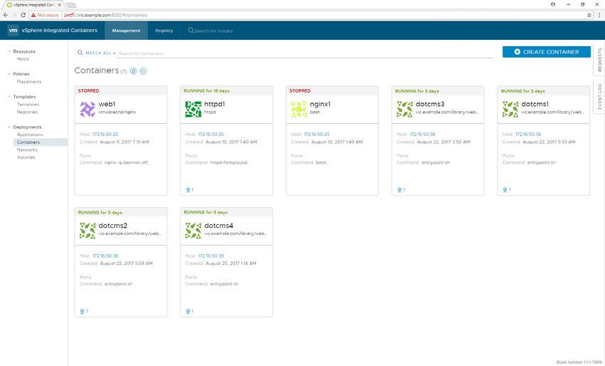
Reference Architecture | A Secure, Unified Cloud Platform to Host Both VM-based and Container-based Applications

Contents
                                                                                                       However, a challenge arises for many DevOps engineers and IT ops teams as
Executive Summary .  .  .  .  .  .  .  .  .  .  .  .  .  .  .  .  .  .  .  .  . 1                      containers continue to grow in popularity among developers: how can today’s
Building a Unified Cloud Platform for VMs
                                                                                                       software-defined data centers (SDDCs) add support for containers in the most
and Containers.  .  .  .  .  .  .  .  .  .  .  .  .  .  .  .  .  .  .  .  .  .  .  .  .  . 1           frictionless way possible while also taking into consideration the security,
                                                                                                       compliance, and monitoring that enterprise applications need?
     What Is VMware Cloud Foundation™?. .  . 2
                                                                                                       VMware Cloud Foundation deployed with vSphere Integrated Containers
     What Is VMware vSphere® Integrated
                                                                                                       offers a simple and compelling solution for securing and supporting containers
     Containers™? .  .  .  .  .  .  .  .  .  .  .  .  .  .  .  .  .  .  .  .  .  .  .  .  . 2
                                                                                                       within existing environments that already support VMs based on VMware
Solution Architecture. .  .  .  .  .  .  .  .  .  .  .  .  .  .  .  .  .  .  . 3                       ESXi™, without requiring any retooling or rearchitecting of the network. Cloud
     Overview.  .  .  .  .  .  .  .  .  .  .  .  .  .  .  .  .  .  .  .  .  .  .  .  .  .  .  .  . 3
                                                                                                       Foundation with vSphere Integrated Containers provides a unified, seamless
                                                                                                       platform for managing both VMs and Docker containers in a way that builds
     Solution Architecture: Software .  .  .  .  .  .  . 3                                             on a company’s existing VMware® security infrastructure and administrators’
     Solution Architecture: Hardware.  .  .  .  .  .  . 4                                              familiarity with vSphere.

Configuration Guidance. .  .  .  .  .  .  .  .  .  .  .  .  .  .  .  .  . 6
                                                                                                       What Is VMware Cloud Foundation™?
     Overview of the Configuration Steps .  .  . 6
                                                                                                       VMware Cloud Foundation is a suite of services, built on the vSphere cloud
     Installing and Configuring VMware                                                                 computing platform, whose components work together to provide a managed,
     Cloud Foundation.  .  .  .  .  .  .  .  .  .  .  .  .  .  .  .  .  .  .  .  . 6                   hyper-converged, and highly secure cloud-software infrastructure for VM-
     Installing and Configuring vSphere                                                                based workloads. The main components in the VMware Cloud Foundation suite
     Integrated Containers.  .  .  .  .  .  .  .  .  .  .  .  .  .  .  .  . 9                          are vSphere, VMware NSX®, VMware vSAN™, and VMware SDDC Manager™.

     Understanding the vSphere Integrated
     Containers Workflow. .  .  .  .  .  .  .  .  .  .  .  .  .  .  .  . 11
                                                                                                       What Is VMware vSphere® Integrated Containers™?
                                                                                                       vSphere Integrated Containers is a Docker-compatible container engine that can
     Understanding Virtual Container Hosts.  11
                                                                                                       be installed on top of vSphere to extend the hosting and management capabilities
Walkthrough: Containerizing and                                                                        of that platform to include containers. Once vSphere Integrated Containers is
Deploying an Application in vSphere                                                                    installed, both developers and administrators can provision and manage containers
Integrated Containers .  .  .  .  .  .  .  .  .  .  .  .  .  .  .  .  .  . 15                          through the VMware Cloud Foundation management tools and a command
     Overview of the Deployment                                                                        prompt. vSphere Integrated Containers also extends the management functionality
     Procedure .  .  .  .  .  .  .  .  .  .  .  .  .  .  .  .  .  .  .  .  .  .  .  .  .  .  . 16      of VMware Cloud Foundation by allowing developers to securely store and manage
                                                                                                       both container images and running instances of containerized apps.
     Configuring Load Balancing and
     Microsegmentation in VMware NSX .  .  . 23                                                        This document describes a specific do-it-yourself (DIY)-type implementation
     Configuring Microsegmentation. . . . . . 25                                                       of this cloud platform and provides details about the specific hardware and
                                                                                                       software needed for deployment. The particular implementation described in
Summary .  .  .  .  .  .  .  .  .  .  .  .  .  .  .  .  .  .  .  .  .  .  .  .  .  .  .  .  .  . 28    this reference architecture runs on qualified Dell EMC™ and Intel hardware and
Appendix/Additional Resources. .  .  .  .  .  .  .  . 28                                               has been validated as a fully functional solution by a team of Intel engineers.

                                                                                                       Figure 1. The validated solution described in this paper consists of VMware
                                                                                                       vSphere Integrated Containers and VMware Cloud Foundation running on Dell
                                                                                                       EMC PowerEdge servers with Intel® SSDs

                                                                                                                                                                                           2
Reference Architecture | A Secure, Unified Cloud Platform to Host Both VM-based and Container-based Applications

                                                                            VMware Cloud Foundation provides this unified management
Solution Architecture                                                       interface across switches, servers, and server-based storage.
                                                                            It presents an abstracted view of physical resources (CPU,
Overview                                                                    memory, storage, and network) as resource pools for
                                                                            operations management, event reporting, and auditing.
The solution described in this reference architecture consists              VMware Cloud Foundation also introduces a new abstraction,
of a single rack composed of a specific set of software and                 workload domains, for creating logical pools of combined
hardware components. The following sections review the                      compute, storage, and networking resources.
software components that make up the unified VMware
Cloud Foundation and vSphere Integrated Containers
solution, followed by the specific hardware components
in the rack. Finally, the document proceeds to describe the
steps needed to configure the solution out of the hardware
and software components.

Solution Architecture: Software
The software inventory of the solution includes VMware
Cloud Foundation, vSphere Integrated Containers, and
some optional software components that can extend the
functionality of the solution.
The following software components are described in
this section:                                                               Figure 3. Workload domains allow admins to allocate CPU,
  • VMware Cloud Foundation                                                 memory, and storage resources to workloads and projects
     • VMware vSphere
     • VMware NSX                                                           VMware vSphere®
     • VMware vSAN                                                          vSphere is VMware’s cloud computing platform, consisting
     • VMware SDDC Manager                                                  of a type-1 hypervisor (ESXi), a virtual management server
  • vSphere Integrated Containers                                           (VMware vCenter Server®) for each workload or management
      • vSphere Integrated Containers Engine                                domain, and an administration interface (vSphere Web
      • vSphere Integrated Containers Registry                              Client) to manage VMs and other virtualized components
      • vSphere Integrated Containers Management Portal                     in the SDDC. vSphere also includes Platform Services
                                                                            Controller™—a service that handles network-wide security
  • Optional components                                                     functions such as single sign-on (SSO), licensing, and
     • VMware Horizon® Suite                                                certificate management.
     • VMware vRealize® Suite
                                                                            VMware NSX®
VMware Cloud Foundation
                                                                            VMware NSX is VMware’s network virtualization software.
VMware Cloud Foundation is a unified SDDC platform for                      VMware NSX allows you to define network connectivity
both private and public clouds. VMware Cloud Foundation                     among virtualized elements running on vSphere and to
brings together a hypervisor platform, software-defined                     harden network security through microsegmentation rules.
storage, and network virtualization into an integrated                      Virtual network functions (VNFs) defined by VMware NSX
stack whose resources are managed through a single                          include switching, routing, firewalling, load balancing, and
administrative tool.                                                        VPNs (IPsec and Secure Sockets Layer [SSL]).

                                                                            VMware vSAN™
                                                                            VMware vSAN provides high-performance, hyper-converged
                                                                            storage for VMs in the vSphere environment. It serves as a
            Private cloud                     Public cloud
                                                                            key building block of the hyper-converged infrastructure
                                                                            that is integrated with vCenter Server. Through vSAN, flash
                      VMware Cloud Foundation™
                                                                            storage is pooled from multiple hosts, and virtual disks are
                                                                            provisioned as needed from the available space.

                                                                            VMware SDDC Manager™
           VMware vSphere®    VMware vSAN™       VMware NSX®                SDDC Manager is the administration tool native to VMware
                                                                            Cloud Foundation through which you can provision, manage,
                       VMware SDDC Manager™                                 and monitor both the logical and physical resources of a
                                                                            VMware Cloud Foundation deployment. SDDC Manager helps
                                                                            admins perform tasks in the following areas:
Figure 2. VMware Cloud Foundation is a cloud solution                         • Infrastructure services: Manage physical resources by
managed through VMware SDDC Manager and built on                                adding and removing racks or by adding and removing
VMware vSphere, VMware vSAN, and VMware NSX                                     hosts and switches on a rack.
                                                                                                                                            3
Reference Architecture | A Secure, Unified Cloud Platform to Host Both VM-based and Container-based Applications

  • Workload domain management: Consolidate the
    physical resources of an SDDC into one or more logical
    entities. Orchestrate the shutdown and boot of logical
    software and management components within a VMware
    Cloud Foundation deployment.
  • Lifecycle management: Configure automatic upgrades
    and patching.

                                                                            Figure 5. The VMware vSphere Integrated Containers
                                                                            management portal, or “Admiral,” presents a view of the
                                                                            containers and container images available on the network

                                                                            Optional Components
                                                                            Two optional components, VMware Horizon Suite and
                                                                            VMware vRealize Suite, can be added to extend the
Figure 4. VMware SDDC Manager allows administrators to                      functionality and management scope of a VMware Cloud
manage physical resources and divide capacity into logical                  Foundation deployment. When these applications suites are
workload domains                                                            added, their functionality is fully integrated into VMware
                                                                            Cloud Foundation management tools. They both require
vSphere Integrated Containers                                               additional licensing fees.

vSphere Integrated Containers is a runtime environment
                                                                            VMware Horizon® Suite
for Docker containers in vSphere. A software extension
to vSphere, vSphere Integrated Containers allows                            This optional software suite, which includes the components
administrators to provision Docker containers in vSphere and                VMware Horizon 7 and VMware App Volumes™, provides
manage them in the same way as VMs.                                         support for the management of a virtual desktop
                                                                            infrastructure (VDI) within VMware Cloud Foundation.
vSphere Integrated Containers includes the vSphere
Integrated Containers Engine, the vSphere Integrated                        For more information about VMware Horizon Suite, visit
Containers Registry, and the vSphere Integrated Containers                  vmware.com/products/desktop-virtualization.html.
Management Portal.
                                                                            VMware vRealize® Suite
vSphere Integrated Containers Engine                                        The VMware vRealize Suite includes VMware vRealize®
                                                                            Operations™, VMware vRealize® Automation™, VMware vRealize®
The vSphere Integrated Containers Engine is a Docker
                                                                            Business™, and VMware vRealize® Log Insight™. Including this
remote API-compatible engine that runs container images in
                                                                            suite as part of a VMware Cloud Foundation deployment can
vSphere as VMs.
                                                                            extend the automation, monitoring, management, and analytics
                                                                            capabilities of your cloud infrastructure.
vSphere Integrated Containers Registry (“Harbor”)
                                                                            For more information on vRealize Suite, visit vmware.com/
The vSphere Integrated Containers registry, nicknamed
                                                                            products/vrealize-suite.html.
“Harbor,” is a private registry for Docker images. It acts as
a private, secure alternative to the public Docker Hub*. The
vSphere Integrated Containers registry is intended to be
                                                                            Solution Architecture: Hardware
hosted on a private, internal network and, unlike Docker                    The hardware used to build this particular solution includes
Hub, it includes features and functionalities that are usually              12 servers and 4 switches in a single rack. (One switch was
required by private enterprises, such as security, identity, and            used only for imaging and is not required by the solution. See
management capabilities.                                                    Table 2 for more information.)

vSphere Integrated Containers Management Portal                             What’s in the Rack? Servers and Server Components
(“Admiral”)                                                                 This reference architecture uses the server components
                                                                            shown in Table 1.
The web-administration interface, nicknamed “Admiral,” is a
management portal that provides development teams with                      Note that the network adapter includes two 10 Gb ports,
a way to manage container registries, images, hosts, and                    both of which are used. Note also that two different types of
running instances.                                                          Intel SSDs are used: the higher-performing SSDs are reserved
                                                                            for the caching tier, whereas the lower-cost SSDs are used for
                                                                            the data tier.

                                                                                                                                             4
Reference Architecture | A Secure, Unified Cloud Platform to Host Both VM-based and Container-based Applications

 Table 1. Server and server components used in the reference architecture

 Component                         Details                                                                                        Quantity
 Server                            Dell EMC PowerEdge R630 rack server                                                            12

 CPU                               Intel® Xeon® processor E5-2660 v4 (2.0 GHz, 14 cores, 35M cache, 105 W)                        2 per server

 Memory                            32 GB DDR4, 2400 MHz memory modules (256 GB total)                                             8 per server

 Storage (caching tier)            800 GB, 2.5 in. Serial ATA (SATA) Intel® SSD DC S3710 Series                                   2 per server

 Storage (data tier)               800 GB, 2.5 in. SATA Intel SSD DC S3520 Series                                                 8 per server

 Storage controller                Dell EMC PowerEdge HBA330 Mini-Serial Attached SCSI (SAS), firmware version                    1 per server
                                   13.17.03.00

 Network adapter                   Dual-port 10 gigabit (Gb) Intel® Ethernet Converged Network Adapter X520 DP 10Gb               1 per server
                                   DA/SFP+ and dual-port 1 Gb Intel® Ethernet Server Adapter I350 Network Daughter
                                   Card
 Boot device                       Dell™ Internal Dual SD Module (IDSDM), 2 x 16 GB SD cards                                      1 per server

What’s in the Rack? Networking Components
For networking components, the reference architecture uses                     VMware Cloud Foundation Deployments
the items shown in Table 2.                                                    VMware Cloud Foundation deployments can scale
Note that the Dell Networking S3048-ON switch supports                         from a single rack up to eight racks. In a multiple-rack
the Open Network Operating System* (ONOS*). This                               deployment, you also need a pair of spine switches,
feature is key because open networking is what enables                         usually located in the second rack. For single-rack
the lifecycle management and provisioning of the switch                        deployments, such as this one, you don’t need any
through SDDC Manager.                                                          spine switches. For more information, see the VMware
                                                                               Cloud Foundation Overview and Bring-Up Guide,
Note also that the Dell Networking S60 switch is not required                  available at http://docs.vmware.com/en/
by VMware Cloud Foundation. It is used for the initial server                  VMware-Cloud-Foundation/2.2/
imaging process as a private managed switch.                                   vcf-22-ovdeploy-guide.pdf.

 Table 2. Networking components used in the reference architecture

 Role                                  Switch                            Details                                                        Quantity
 Top-of-rack switch                    Cisco Nexus 93180YC-EX            48 x 1/10/25 gigabit per second (Gbps) SFP+ ports*             2
                                       NX-OS 7.0(3)I4(2)*                and 6 x 40/100 Gbps QSFP+ uplink ports*

 Management switch                     Dell Networking S3048-ON          48 x 1-Gbps 1000BASE-T ports* and 4 x 10-Gbps                  1
                                       Cumulus Linux 2.5.8*              SFP+ uplink ports

 Private managed switch**              Dell Networking S60               44 x 10/100/1000BASE-T and 4 x 1 GbE SFP                       1
                                       FTOS 8.3.3.10
                                                                                                             **Optional; used only for the server imaging process

Although other hardware components can be used for this                     Other Hardware Requirements
solution, only the listed components have been validated and
                                                                            After acquiring certified hardware components, you also need
tested for this reference architecture. Unsupported hardware
                                                                            to ensure that certain BIOS options are enabled, and that
components might cause issues that prevent proper installation
                                                                            the network and switch cabling is configured properly. Both
or that impact the stability or usability of the solution.
                                                                            of these configuration steps are described in the “VMware
For a complete list of supported hardware, please refer to the              Cloud Foundation Overview and Bring-Up Guide” document,
VMware Compatibility Guide for VMware Cloud Foundation,                     available at https://docs.vmware.com/en/
located at vmware.com/resources/compatibility/                              VMware-Cloud-Foundation/2.1.3/
search.php?deviceCategory=vcf.                                              vcf-21-ovdeploy-guide.pdf.

                                                                                                                                                                    5
Reference Architecture | A Secure, Unified Cloud Platform to Host Both VM-based and Container-based Applications

                                                                    1 x Dell EMC Networking S3048-ON—Management Switch
                                                                    2 x Cisco Nexus 93180YC-EX—Top-of-Rack Switches
                                                                    12 x Dell EMC PowerEdge R630 (10x 2.5” SFF Hot-Plug
                                                                    Disks)—Compute Resources
                                                                      •   2 x 14-core Intel® Xeon® processor E5-2660 v4, 2.0 GHz
                                                                      •   256 GB RAM (8 x 32 GB DIMMs)
                                                                      •   Dell EMC PowerEdge RAID Controller HBA330
                                                                      •   2 x Intel® SSD DC S3710 Series (Cache)
                                                                      •   8 x Intel SSD DC S3520 Series (Capacity)
                                                                      •   Dual-port 10 gigabit Ethernet (GbE) Intel® Ethernet Converged
                                                                          Network Adapter X520 + 1 GbE Intel® Ethernet Server Adapter I350
                                                                          Network Daughter Card (1 x 10 GbE in use)
                                                                      •   Dual-port 10 GbE Intel Ethernet Converged Network Adapter X520
                                                                          PCIe* Networking Card (1 x 10 GbE in use)
                                                                      •   Dual redundant SD modules with 2 x 16 GB SD card (hypervisor)
                                                                      •   Integrated Dell™ Remote Access Controller (iDRAC) Enterprise
                                                                      •   Dell EMC™ OpenManage™ Essentials Server Configuration Management
                                                                      •   Dual Redundant Hot-Plug Power Supplies (1+1) 750 W

Figure 6. A physical view of the components that make up the solution

Rack Diagram                                                                2.   Perform the bring-up process for VMware Cloud
                                                                                 Foundation. During this step, the system is initialized,
Figure 6 illustrates the placement in the rack of the hardware
                                                                                 configured, and connected to the existing data
components that are required for this reference architecture.
                                                                                 center network.

Configuration Guidance                                                      Imaging the Hardware through the VMware Cloud
The following sections describe the steps you need to take
                                                                            Foundation Imaging Appliance (VIA)
in order to build the solution after you have assembled the                 To complete this step, read the preparatory steps below,
proper hardware in the rack, configured the cabling, and                    and then follow the instructions described in the “VIA User’s
configured all required BIOS settings. Additionally, all disks              Guide” document, which you can find at
should be empty and should not contain any partitions or                    https://docs.vmware.com/en/VMware-Cloud-Foundation/
user data.                                                                  2.1.3/via-21-guide.pdf. As the document indicates, it is
                                                                            recommended that you install VIA on a desktop or laptop
Overview of the Configuration Steps                                         when you want to image a single rack.
The configuration and deployment of the software stack                      To prepare for the procedure, ensure that the first network
involves three steps:                                                       interface in each server has PXE support enabled. The
                                                                            boot sequence should also be configured in a way that
1.   Installing and configuring VMware Cloud Foundation
                                                                            the server first tries to boot from PXE, then from local SD
     (including the workload domains)
                                                                            card (IDSDM). The management switch must be in Open
2.   Installing and configuring vSphere Integrated Containers               Network Install Environment* (ONIE*) install mode, ready
                                                                            for installation of the Cumulus Linux* operating system. The
3.   Containerizing applications                                            Cisco switches should contain no configuration and should
                                                                            be in the PowerOn Auto Provisioning (POAP) mode. Finally,
Installing and Configuring VMware                                           all SD cards and SSDs should be empty. If the servers were
Cloud Foundation                                                            previously used, these drives should be cleared of all data,
Two steps are required to install and configure VMware                      because it could interfere with the imaging process.
Cloud Foundation:                                                           During the imaging process, you can observe the progress
1.   Image the hardware through the VMware Cloud Foundation                 of imaging each component and view detailed logs through
     imaging appliance (VIA). During this step, the appropriate             the same web interface. In case of failure, you can restart
     software components and their initial configuration                    the whole process for any specific device. Properly imaged
     settings are loaded onto each server and switch, and a                 devices will be marked with a green check mark.
     complete inventory of the hardware is built and saved.

                                                                                                                                             6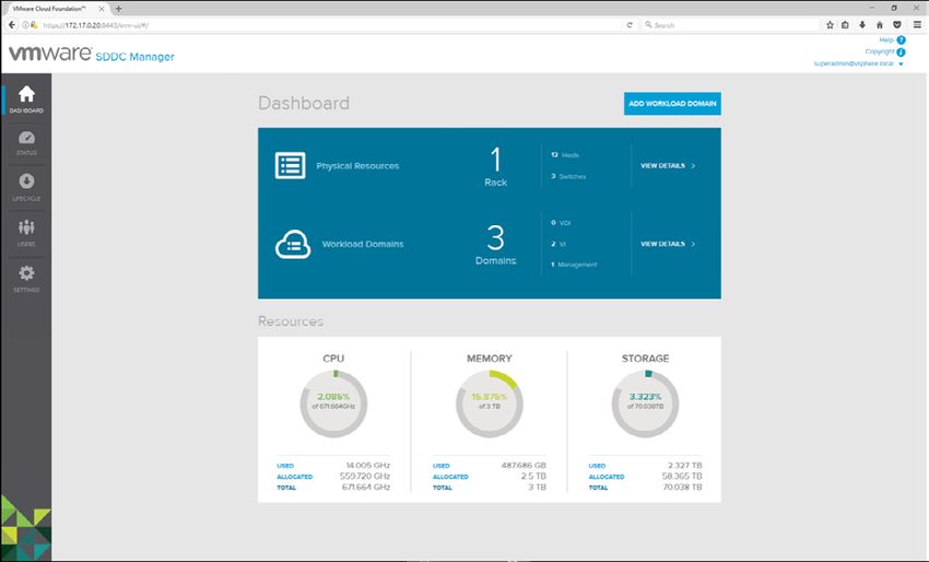
Reference Architecture | A Secure, Unified Cloud Platform to Host Both
                                                                  both VM-based and Container-based Applications

Figure 7. The imaging process after completion
When the imaging process completes, VIA performs
additional verification and uploads to the appropriate servers
Secure Shell (SSH) keys, certificates, and the inventory
database built during the imaging process.
The last step in the imaging process is to obtain the
bootstrap passwords, including the password for the
SDDC Manager VM (also called the VRM virtual machine),
which will be needed later on during the bring-up process.
The passwords are provided by VIA under the URL
http://192.168.100.2:8080/via/ipsecThumbprint/runId,
where runId is the run number. (VIA can be used for imaging
multiple racks, in which case each imaging process is a
separate run. You can find the run number or run ID in the
top-left corner of Figure 7.)                                               Figure 8. A running log of the bring-up process
                                                                            The next step of the bring-up process is to supply a new
Bring Up VMware Cloud Foundation                                            account name and password for the administrator account,
Once the imaging process is complete, you can move on to                    in addition to some general information like a physical rack
the second phase—bringing up VMware Cloud Foundation.                       name, a root Domain Name System (DNS) domain name, the
The bring-up process is handled by SDDC Manager. A detailed                 VMware Cloud Foundation subdomain, the SSO domain, and
explanation of this procedure is described in the “VMware                   finally the VMware Cloud Foundation license key.
Cloud Foundation Overview and Bring-Up Guide” document
available at https://docs.vmware.com/en/
VMware-Cloud-Foundation/2.1.3/vcf-21-ovdeploy-guide.pdf.
As with the VIA appliance, SDDC Manager is accessed through
a standard web browser.
Before you start the bring-up process, first collect all the
information needed to configure network connectivity,
including a list of VLANs, network addresses, and uplinks.
When you access the SDDC Manager interface for the first time,
the system automatically sets the proper time and time zone on
all components. It also performs several basic checks to verify
that all components are accessible and in the expected state.

                                                                            Figure 9. Entering basic information as part of the bring-up process
                                                                                                                                                   7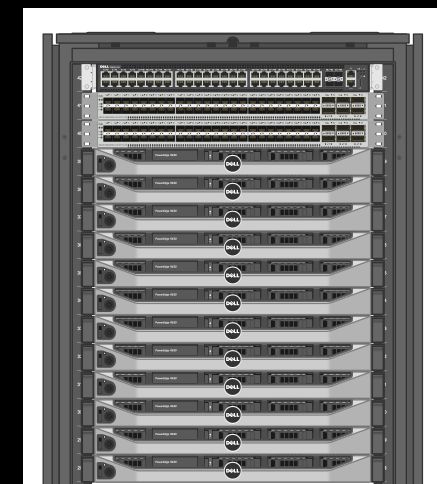
Reference Architecture | A Secure, Unified Cloud Platform to Host Both VM-based and Container-based Applications

Next is network configuration, where you provide VLAN and                   nodes are reserved for management purposes, and they
IP addresses for management, VMware vSphere® vMotion®,                      contain all the components needed to manage the whole
vSAN, a Virtual Extensible LAN (VXLAN) overlay, an external                 infrastructure. You should not deploy any user applications
data center network, and data center uplinks.                               on this management cluster. Instead, you should create
                                                                            one or more workload domains that comprise a separate
Finally, there is a short summary page that displays all the
                                                                            vSphere cluster with vSAN and VMware NSX pre-installed
information you have provided. This is followed by the
                                                                            and configured along with a dedicated instance of vCenter
Component IP Allocation page, which shows the names and
                                                                            Server for management purposes.
IP addresses assigned to specific components.
                                                                            In addition to management domains, there are two other types
                                                                            of workload domains that can be created in SDDC Manager:
                                                                              • Virtual infrastructure (VI): General purpose domain
                                                                              • VDI: Dedicated to virtual desktop environments. These
                                                                                workload domains rely on VMware Horizon Suite, which
                                                                                is not part of this reference architecture.
                                                                            The VI workload domain type represents a cluster of
                                                                            resources that can contain up to 64 servers with its own
                                                                            vCenter Server appliance, integrated vSAN, and VMware
                                                                            NSX. A VI workload domain can span multiple racks, so if you
                                                                            later add more racks to this single-rack implementation, you
                                                                            can scale any existing VI workload domains to the additional
                                                                            racks as needed.
                                                                            All the tasks related to the workload domains are performed
                                                                            using the SDDC Manager web interface. This includes the
                                                                            creation, expansion, and deletion of workload domains, along
                                                                            with physical infrastructure monitoring and management.

Figure 10. Important IP address assignments are displayed at
the end of the bring-up process
The Component IP Allocation page is important. Be sure to
record the names and IP addresses listed for “vCenter” and
“VRM VIP,” where SDDC Manager is running. These are
the two main interfaces that you will use to manage the
whole infrastructure.
The VRM VM also hosts the DNS server for the VMware Cloud
Foundation sub-domain provided in an earlier step (in this
example, vcf.example.com), so you should configure your
enterprise DNS servers to forward all queries for that domain
to the VRM VIP IP address.
After you click Confirm, SDDC Manager begins the
configuration and bring-up process. This process can
take up to an hour or two, depending on the number and
configuration of servers. You can follow the progress of the
bring-up process by using the same web interface.
One of the last steps in the bring-up process is to generate
new passwords for all the components. To perform this
step, you have to use SSH to connect to the VRM VM, and                     Figure 11. SDDC Manager allows you to assign CPU, memory,
then run the following command: /home/vrack/bin/                            and storage resources into workload domains
vrm-cli.sh rotate-all. Next, use the same tool with the
                                                                            Creating a new workload domain is simple. After you provide the
lookup-passwords argument to retrieve the newly generated
                                                                            name, you need only to specify the required performance (low,
passwords. This step will retrieve the passwords for all
                                                                            balanced, or high), the desired availability level (none, normal,
physical and logical components, including switches, servers,
                                                                            or high), and the minimum resources needed (for CPU, memory,
vCenter Server, and VMware NSX.
                                                                            and storage space). These settings are shown in Figure 12.
Creating Workload Domains
When the bring-up process completes, the infrastructure
is ready for the creation of workload domains. In the
current version of VMware Cloud Foundation, the first four

                                                                                                                                                8
Reference Architecture | A Secure, Unified Cloud Platform to Host Both VM-based and Container-based Applications

                                                                            Installing and Configuring vSphere
                                                                            Integrated Containers
                                                                            About vSphere Integrated Containers
                                                                            vSphere Integrated Containers is composed of three
                                                                            main components:
                                                                              • VMware vSphere Integrated Containers Engine
                                                                              • VMware vSphere Integrated Containers Registry (Harbor)
                                                                              • VMware vSphere Integrated Containers Management
                                                                                Portal (Admiral)
                                                                            vSphere Integrated Containers Engine supports a
                                                                            subset of the Docker API as a way to allow developers
                                                                            and administrators to provision and run containerized
                                                                            applications alongside traditional VM-based workloads.
                                                                            vSphere Integrated Containers Engine allows administrators
                                                                            to easily manage these workloads through the familiar
                                                                            vSphere user interface (UI).
                                                                            Harbor is an enterprise-class container registry used for storing
                                                                            and distributing container images with applications. It extends
                                                                            the standard open-source registry with security, identity, and
Figure 12. Creating a workload domain                                       management functions often required by enterprises.
The last step is selecting which data center connection (uplink)            Admiral is a container-management portal that provides a
should be used for your workload domains. You can share a                   convenient UI for DevOps teams and admins to provision
single connection for all workload domains or have separate                 and manage containers. It can be further integrated with
connections for each of them. SDDC Manager then determines                  vRealize Automation to provide more advanced capabilities,
how many servers are needed to satisfy those requirements                   like deployment blueprints, allowing the construction of
and presents a suggested configuration for review.                          enterprise-grade containers as a service (CaaS).
When you click Finish, the provisioning process starts in                   All components are available as open-source projects on
the background. This provisioning process installs and                      GitHub* at https://vmware.github.io/vic-product/.
configures all the needed components (including vCenter
                                                                            To obtain the latest official, fully supported releases, you
Server, vSAN, and VMware NSX). It then performs all the
                                                                            need a vSphere Enterprise Plus license.
steps needed to integrate these components, including
creating new VLANs on the switches and reconfiguring the
ports leading to selected servers.                                          Installing vSphere Integrated Containers
                                                                            For the latest official release of vSphere Integrated
The time needed to create a workload domain depends on
                                                                            Containers, you need to download the vSphere Integrated
the server configuration and the requested infrastructure
                                                                            Containers OVA-format image from the VMware portal at
size. In the example environment, the process took our
                                                                            vmware.com/go/download-vic. The 1.1.1 version used in this
engineering team 55 minutes to provision the complete
                                                                            reference architecture is about 2.7 GB.
infrastructure of a workload domain with three servers. So,
in less than an hour, you can achieve what used to require                  You install vSphere Integrated Containers by deploying
weeks before the automation provided by SDDC Manager in                     the virtual appliance you downloaded in the previous
VMware Cloud Foundation was available.                                      step. During the deployment process, you need to specify
                                                                            several parameters, such as the appliance IP address and
Moreover, because the whole process is automated, there is a
                                                                            the administrator passwords for several components. You
much lower risk of the kind of misconfiguration that can often
                                                                            also need to specify whether you want to deploy Harbor and
occur during manual installation. Such configuration errors
                                                                            Admiral. If this is your first vSphere Integrated Containers
could historically lead to serious issues or additional delays
                                                                            deployment, you should deploy both.
in infrastructure provisioning.
Later, you can use SDDC Manager to add new servers to
an existing workload domain as needed. And when you
no longer need the infrastructure used previously by the
workload domain, you can remove it and return unused
servers to the pool of available resources.

                                                                                                                                                9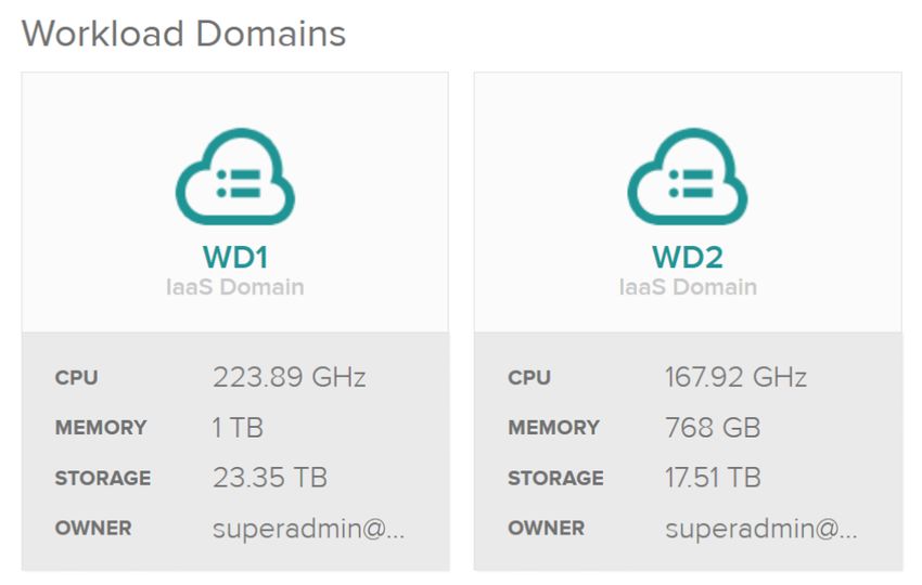
Reference Architecture | A Secure, Unified Cloud Platform to Host Both VM-based and Container-based Applications

                                                                            To complete the procedure for installing vSphere Integrated
                                                                            Containers, follow the detailed instructions found in the
                                                                            product documentation at the following address:
                                                                            https://vmware.github.io/vic-product/assets/files/html/1.1/
                                                                            Because vSphere Integrated Containers is tightly coupled
                                                                            with vCenter Server, you need to deploy the appliance to the
                                                                            same workload domain where you want to run your workloads.
                                                                            Note that it doesn’t have to be a workload domain dedicated
                                                                            entirely to vSphere Integrated Containers; you can run
                                                                            traditional VMs and containers in the same workload domain
                                                                            next to each other with dedicated resources assigned to them.
                                                                            This is a key feature of vSphere Integrated Containers: to enable
                                                                            admins and developers to create and manage containers in a
                                                                            way that is fully integrated into their VM infrastructure. Running
                                                                            both workloads together, in fact, allows deployment of hybrid
                                                                            multi-tier applications where some components run as VMs
                                                                            and others run in easily scalable containers.

                                                                            Unpacking vSphere Integrated Containers Binaries
                                                                            The next step in installing vSphere Integrated Containers is
                                                                            to download and unpack the vSphere Integrated Containers
                                                                            Engine binaries from https://vic_appliance_address:9443
Figure 13. Configuration options for installing vSphere                     to an administrator’s workstation. This package contains
Integrated Containers                                                       the vic-machine utility, which is used to deploy virtual
                                                                            container hosts (VCHs). You can also use the vSphere Web
                                                                            Client Integration Plugin to enable unified management of
                                                                            containers and vSphere resources, including VMs.
                                                                            To unpack the vSphere Integrated Containers Engine
                                                                            binaries, enter the command on the first line to the right
                                                                            (which is followed by output):

  admin@localhost ~ $ curl -O -k https://172.16.0.100:9443/vic _ 1.1.1.tar.gz
    % Total    % Received % Xferd Average Speed      Time     Time       Time Current
                                   Dload Upload      Total   Spent      Left Speed
  100 223M 100 223M      0     0    193M      0 0:00:01 0:00:01 --:--:-- 193M

  admin@localhost ~ $ ls -l
  total 229076
  -rw-r--r--. 1 admin admin 234566550 Aug        8 13:48 vic _ 1.1.1.tar.gz

  admin@localhost ~ $ tar zxvf vic _ 1.1.1.tar.gz
  vic/
  vic/vic-machine-windows.exe
  vic/vic-ui-darwin
  vic/appliance.iso
  vic/README
  vic/bootstrap.iso
  vic/vic-machine-darwin
  vic/vic-ui-linux
  vic/ui/
  vic/ui/plugin-manifest
  vic/ui/VCSA/
  vic/ui/VCSA/configs
  vic/ui/VCSA/install.sh
  vic/ui/VCSA/upgrade.sh
  vic/ui/VCSA/uninstall.sh
  vic/ui/plugin-packages/
  vic/ui/plugin-packages/com.vmware.vic-v1.1.1.zip
  vic/ui/plugin-packages/com.vmware.vic-v1.1.1/
  vic/ui/plugin-packages/com.vmware.vic-v1.1.1/plugins/
  vic/ui/plugin-packages/com.vmware.vic-v1.1.1/plugins/vlsiCore.jar
  vic/ui/plugin-packages/com.vmware.vic-v1.1.1/plugins/vim25.jar
  vic/ui/plugin-packages/com.vmware.vic-v1.1.1/plugins/gson-2.3.1.jar
  vic/ui/plugin-packages/com.vmware.vic-v1.1.1/plugins/vic-service.jar
  vic/ui/plugin-packages/com.vmware.vic-v1.1.1/plugins/vic.war
  vic/ui/plugin-packages/com.vmware.vic-v1.1.1/plugin-package.xml
  vic/ui/vCenterForWindows/

                                                                                                                            (continued on next page)
                                                                                                                                                       10
Reference Architecture | A Secure, Unified Cloud Platform to Host Both VM-based and Container-based Applications
vic/ui/vCenterForWindows/upgrade.bat
vic/ui/vCenterForWindows/uninstall.bat
vic/ui/vCenterForWindows/configs
vic/ui/vCenterForWindows/install.bat
vic/ui/vsphere-client-serenity/
vic/ui/vsphere-client-serenity/com.vmware.vic.ui-v1.1.1.zip
vic/ui/vsphere-client-serenity/com.vmware.vic.ui-v1.1.1/
vic/ui/vsphere-client-serenity/com.vmware.vic.ui-v1.1.1/plugins/
vic/ui/vsphere-client-serenity/com.vmware.vic.ui-v1.1.1/plugins/vic-ui-service.jar
vic/ui/vsphere-client-serenity/com.vmware.vic.ui-v1.1.1/plugins/vim25.jar
vic/ui/vsphere-client-serenity/com.vmware.vic.ui-v1.1.1/plugins/vic-ui-war.war
vic/ui/vsphere-client-serenity/com.vmware.vic.ui-v1.1.1/plugin-package.xml
vic/LICENSE
vic/vic-machine-linux
vic/vic-ui-windows.exe
admin@localhost ~ $ cd vic
admin@localhost ~/vic $ ln vic-machine-linux vic-machine
admin@localhost ~/vic ./vic-machine
NAME:
vic-machine - Create and manage Virtual Container Hosts
USAGE:
vic-machine [global options] command [command options] [arguments...]
VERSION:
v1.1.1-10711-56a309f
COMMANDS:
create Deploy VCH
delete Delete VCH and associated resources
ls List VCHs
inspect Inspect VCH
upgrade Upgrade VCH to latest version
version Show VIC version information
debug Debug VCH
update Modify configuration
help, h Shows a list of commands or help for one command
GLOBAL OPTIONS:
--help, -h show help
--version, -v print the version
Understanding the vSphere Integrated appear to run within specific VCHs. More specifically, a VCH is
deployed as a virtual application (vApp) in a vSphere cluster,
Containers Workflow and all VMs running containers are represented as children of
vSphere Integrated Containers Engine is an enterprise a specific VCH in the user interface.
deployment target for portable Docker containers. The From a technical perspective, however, VCHs do not truly
following steps make up the typical workflow for using host containers by providing a shared kernel or OS upon
vSphere Integrated Containers: which containers run. Instead, an endpoint VM representing
a VCH runs side by side with containers, which all run within
1. Developers build containers in their development
their own VMs called “container VMs.” Each container VM—
environments by using either a local Docker host and the endpoint VM itself—runs a minimal, quick-booting
or a remote Docker endpoint provided by vSphere OS, called Photon OS™.
Integrated Containers.
The Docker API endpoint that runs in the VCH translates
2. A built container image is then pushed to the private Docker commands to the vSphere environment. For example,
enterprise registry, provided by Harbor. when the Docker endpoint receives Docker commands such
as “run” and “build,” the VCH instructs the vCenter Server to
3. The application can be deployed from the registry to test create a VM running the Photon OS kernel and to unpack the
separate environments. Docker image into that VM. Other commands are translated
and executed against the containers of the VCH.
4. Finally, the application is deployed from the registry to
a production environment that is also running vSphere A VCH is easy to scale as a resource pool. To do so, just add
Integrated Containers Engine on top of vSphere. an ESXi host to the workload vSphere cluster to increase
the capacity without disrupting the existing containers.
Understanding Virtual Container Hosts You can also deploy multiple VCHs in the same cluster.
Doing so allows you to easily provide fully separated and
A VCH is a resource pool that is mapped to an endpoint secure environments for multiple tenants sharing the same
VM and that acts as a Docker host in vSphere Integrated underlying infrastructure.
Containers. From a management perspective, a VCH looks very
similar to a VM that hosts Docker containers, and containers To create and configure a VCH, use the vic-machine
command-line utility.
11Reference Architecture | A Secure, Unified Cloud Platform to Host Both VM-based and Container-based Applications
Figure 14 depicts the relationship between the various Figure 15 illustrates the roles of these different network types.
vSphere Integrated Containers components. In the figure, A1
and A2 represent Docker endpoints, and C1, C2, and C3
represent container VMs. VMware vSphere® Integrated Containers™ Appliance
Management
Registry
Portal
VMware
Docker* VIC
vCenter®
Client Machine Client
Client
Network
Developer
Manages Admin VCH vApp
Manages VCHs
Containers Monitoring
Container-VM Container-VM
Management
VCH
Network
Endpoint
VMware vSphere®/ VM
A1 C1 C3 C2 VMware ESXi™ Container-VM
Public
C1 A2 Network
VMware ESXi™ VMware ESXi™ VMware ESXi™ Bridge Container
Network Network
VMware vCenter®
User
VIC Appliance
Figure 15. Network types and roles1
VICAdmin Docker Docker*
Browser (logs, debug) personality Client When you define a network for vSphere Integrated
Containers, you must specify a port group to associate with
Port Layer Services
(exec, net, storage, event, interact)
the networks you define. Most of the needed port groups for
the VMware Cloud Foundation networks that we will define in
this reference architecture have been created as part of the
To VMware vCenter® SDK imaging process.
For this reference architecture, we will specify a
management, public, bridge, and container network when we
Figure 14. Relationship between VMware vSphere Integrated create the VCH, but we will not define any client networks.
Containers Engine components1 (When no client networks are defined, the default network
used for this purpose is the same as the public network.)
Network Types
For more information about virtual networks used with
The vSphere Integrated Containers Engine uses different vSphere Integrated Containers, visit
network types for different purposes: https://vmware.github.io/vic-product/assets/files/html/1.1/
1. Management network: This network is dedicated to vic_vsphere_admin/networks.html.
communication between the VCH, vCenter Server, and
ESXi hosts. You define the management network by Preparing for VCH Deployment
using the --management-network option when you Before we create the VCH by using the vic-machine utility, we
create the VCH with vic-machine create. need to perform some preparatory steps, such as creating
2. Public network: This network, which is mandatory, a logical switch in VMware NSX for the bridge network and
connects containers to the Internet. You specify the modifying firewall rules.
public network with the --public-network option.
Creating a Logical Switch for the Bridge Network
3. Client network: This network connects Docker clients
to Docker endpoints and isolates the endpoints from The four networks we define when we create the VCH must all
the public network. You define the Docker management be assigned port groups. Of the port groups we will assign, only
endpoint network by setting the --client-network option. the port group for the bridge network has not yet been created.
(The vRack-DPortGroup-External and vRack-DPortGroup-Mgmt
4. Bridge network: This network allows the containers port groups are created and configured automatically during
and the VCH to communicate with each other. Each VCH workload domain creation by SDDC Manager.)
requires a unique bridge network. To specify the bridge
network, use the --bridge-network option when you run However, instead of creating that new port group in vSphere,
vic-machine create. we will create a logical switch in VMware NSX to assign to the
bridge network. We specifically use the Logical Switch feature
5. Container network: This type of network is used to of VMware NSX (instead of vSphere port groups) in order to
connect containers directly to vSphere networks without take advantage of overlay networking and avoid having to
routing through the VCH endpoint VM using NAT. configure any VLANs on the physical switches.
12Reference Architecture | A Secure, Unified Cloud Platform to Host Both VM-based and Container-based Applications
To create the new logical switch in the vSphere Web Client Determining VCH Storage and Compute Resources
interface, navigate to Networking & Security, and then
When you use the vic-machine utility to create the VCH, you
Logical Switches. To begin the process of creating a new
will need to specify a volume store, image store, and compute
logical switch, click the green plus (+) icon. This step opens
resource. For the volume store, we will use vsanDatastore/
the New Logical Switch window shown in Figure 16.
vic-containers:default. For the image store, we will specify
vsanDatastore/vic-images. The compute resource can be a
host, cluster, or resource pool. In our case, we will specify the
compute resource as VCH.
Setting Up the PKI
In production environments, you should deploy valid
public-key infrastructure (PKI) certificates to infrastructure
components. (For instructions on how to perform this step,
use the documentation accompanying your chosen PKI
solution.) As a workaround, you can skip certificate validation
by using the --no-tlsverify and --force options. In this case,
however, you must specify the Secure Hash Algorithm 1
(SHA-1) thumbprint of the vCenter Server certificate with
the --thumbprint option. (This thumbprint can be obtained
by inspecting the certificate in a web browser or by first
attempting to run the command without the --thumbprint
option. Failing to provide this option will generate an error
Figure 16. Creating a new logical switch message that includes the retrieved thumbprint of your
vCenter Server).
From the vSphere perspective, the new logical switch “VCH1-
BRIDGE,” created in VMware NSX, is visible as a distributed For other, more advanced deployment scenarios, please refer
port group with a name like vxw-dvs-9-virtualwire-2-10001- to vSphere Integrated Containers documentation at
VCH1-BRIDGE. For simplicity, you might prefer to rename the https://vmware.github.io/vic-product/assets/files/html/1.1/.
port group to the name used for the associated logical switch
in VMware NSX (as shown in Figure 17). Modifying Firewall Rules
Although we have now created the port group to assign to The next step required is modifying firewall rules on all ESXi
the bridge network, we will create that bridge network later, hosts in the cluster to enable outgoing traffic from each host
when we create the VCH. At that time we will specify this port to the VCH. To perform this step, run the following command
group by its new name, VCH1-BRIDGE. (which appears on the first three lines below, followed by
output), substituting the SHA-1 thumbprint of your own
vCenter Server certificate:
Figure 17. Renaming the port group in VMware vSphere to
match the VMware NSX logical switch name (optional)
admin@localhost ~/vic $ ./vic-machine update firewall --allow --target rack-1-vc-2.vcf.example.com \
--user superadmin@vsphere.local --password P@ssw0rd \
--thumbprint 59:73:5A:C7:BB:B6:02:57:35:D9:4A:9A:6B:9F:51:68:DD:A8:31:BC
Aug 9 2017 14:18:34.000Z INFO ### Updating Firewall ####
Aug 9 2017 14:18:34.112Z INFO Validating target
Aug 9 2017 14:18:34.112Z INFO Validating compute resource
Aug 9 2017 14:18:34.112Z INFO
Aug 9 2017 14:18:34.112Z WARN ### WARNING ###
Aug 9 2017 14:18:34.112Z WARN This command modifies the host firewall on the target machine or cluster
Aug 9 2017 14:18:34.112Z WARN The ruleset “vSPC” will be enabled
Aug 9 2017 14:18:34.112Z WARN This allows all outbound TCP traffic from the target
Aug 9 2017 14:18:34.112Z WARN To undo this modification use --deny
Aug 9 2017 14:18:34.112Z INFO
Aug 9 2017 14:18:34.151Z INFO Ruleset “vSPC” enabled on host “HostSystem:host-20 @ /vRack-Datacenter/host/WD1-0-cluster/172.17.0.25”
Aug 9 2017 14:18:34.185Z INFO Ruleset “vSPC” enabled on host “HostSystem:host-26 @ /vRack-Datacenter/host/WD1-0-cluster/172.17.0.26”
Aug 9 2017 14:18:34.217Z INFO Ruleset “vSPC” enabled on host “HostSystem:host-30 @ /vRack-Datacenter/host/WD1-0-cluster/172.17.0.27”
Aug 9 2017 14:18:34.248Z INFO Ruleset “vSPC” enabled on host “HostSystem:host-72 @ /vRack-Datacenter/host/WD1-0-cluster/172.17.0.42”
Aug 9 2017 14:18:34.248Z INFO
Aug 9 2017 14:18:34.248Z INFO Firewall changes complete
Aug 9 2017 14:18:34.249Z INFO Command completed successfully
13Reference Architecture | A Secure, Unified Cloud Platform to Host Both VM-based and Container-based Applications
In addition, because we are going to secure the internal Increasing the Memory Reserved for the VCH
container registry (Harbor), we need to obtain the certificate
The current version (1.1.1) of vSphere Integrated Containers
authority (CA) certificate used to sign the default self-signed
has a particular limitation: in the process of pulling container
certificate used by Harbor and then provide it as a parameter
images from the registry, a service on the VCH extracts its
to the VCH. To complete this step, enter the command on the
contents to a temporary file system held in memory (tmpfs).
first line below (which appears followed by output):
For large containers, this process might fail if there is not
enough free space. To handle large images properly in
version 1.1.1, we need to increase the memory reservation for
admin@localhost ~/vic $ scp root@vic.example.com:/data/ VCH by adding special parameter --endpoint-memory 8192
harbor/cert/ca.crt ca.crt to the vic-machine create command.
The authenticity of host ‘vic.example.com (172.16.0.100)’
can’t be established. Creating a VCH
ECDSA key fingerprint is SHA256:CRG5YlPQVu9UVwD8IOxrWFOniUA
Finally, you can deploy a new VCH by using the vic-machine
QJh6BRjXIeFKCMR0.
create command. Remember, in production environments
Are you sure you want to continue connecting (yes/no)?
you should deploy valid PKI certificates to infrastructure
yes
components. Again, as a workaround, you can skip certificate
Warning: Permanently added ‘vic.example.com,172.16.0.100’
validation by using the --no-tlsverify and --force options and
(ECDSA) to the list of known hosts.
specifying a thumbprint instead with the --thumbprint option.
Password:
ca.crt Run the following command (which appears on the first 15
lines below, followed by output) to create the VCH:
admin@localhost ~/vic $ ./vic-machine create --target rack-1-vc-2.vcf.example.com \
--user superadmin@vsphere.local --password P@ssw0rd \
--thumbprint 59:73:5A:C7:BB:B6:02:57:35:D9:4A:9A:6B:9F:51:68:DD:A8:31:BC --name VCH1 \
--compute-resource VCH --image-store vsanDatastore/vic-images \
--volume-store vsanDatastore/vic-containers:default --bridge-network VCH1-BRIDGE \
--bridge-network-range 192.168.0.0/16 --public-network vRack-DPortGroup-External \
--management-network vRack-DPortGroup-Mgmt --container-network vRack-DPortGroup-External \
--registry-ca=ca.crt --no-tlsverify --force --endpoint-memory 8192
Aug 9 2017 15:07:21.055Z INFO ### Installing VCH ####
Aug 9 2017 15:07:21.055Z WARN Using administrative user for VCH operation - use --ops-user to improve security (see -x for advanced help)
Aug 9 2017 15:07:21.057Z INFO Loaded server certificate VCH1/server-cert.pem
Aug 9 2017 15:07:21.057Z WARN Configuring without TLS verify - certificate-based authentication disabled
Aug 9 2017 15:07:21.057Z INFO Loaded registry CA from ca.crt
Aug 9 2017 15:07:21.155Z INFO Validating supplied configuration
Aug 9 2017 15:07:21.260Z INFO vDS configuration OK on “VCH1-BRIDGE”
Aug 9 2017 15:07:21.266Z INFO vDS configuration OK on “vRack-DPortGroup-External”
Aug 9 2017 15:07:21.292Z INFO Firewall status: ENABLED on “/vRack-Datacenter/host/WD1-0-cluster/172.17.0.25”
Aug 9 2017 15:07:21.309Z INFO Firewall status: ENABLED on “/vRack-Datacenter/host/WD1-0-cluster/172.17.0.26”
Aug 9 2017 15:07:21.327Z INFO Firewall status: ENABLED on “/vRack-Datacenter/host/WD1-0-cluster/172.17.0.27”
Aug 9 2017 15:07:21.344Z INFO Firewall status: ENABLED on “/vRack-Datacenter/host/WD1-0-cluster/172.17.0.42”
Aug 9 2017 15:07:21.352Z INFO Firewall configuration OK on hosts:
Aug 9 2017 15:07:21.352Z INFO “/vRack-Datacenter/host/WD1-0-cluster/172.17.0.25”
Aug 9 2017 15:07:21.352Z INFO “/vRack-Datacenter/host/WD1-0-cluster/172.17.0.26”
Aug 9 2017 15:07:21.352Z INFO “/vRack-Datacenter/host/WD1-0-cluster/172.17.0.27”
Aug 9 2017 15:07:21.352Z INFO “/vRack-Datacenter/host/WD1-0-cluster/172.17.0.42”
Aug 9 2017 15:07:21.403Z INFO License check OK on hosts:
Aug 9 2017 15:07:21.403Z INFO “/vRack-Datacenter/host/WD1-0-cluster/172.17.0.25”
Aug 9 2017 15:07:21.403Z INFO “/vRack-Datacenter/host/WD1-0-cluster/172.17.0.26”
Aug 9 2017 15:07:21.403Z INFO “/vRack-Datacenter/host/WD1-0-cluster/172.17.0.27”
Aug 9 2017 15:07:21.403Z INFO “/vRack-Datacenter/host/WD1-0-cluster/172.17.0.42”
Aug 9 2017 15:07:21.421Z INFO DRS check OK on:
Aug 9 2017 15:07:21.421Z INFO “/vRack-Datacenter/host/WD1-0-cluster”
Aug 9 2017 15:07:21.454Z INFO
Aug 9 2017 15:07:21.593Z INFO Creating virtual app “VCH1”
Aug 9 2017 15:07:21.635Z INFO Creating directory [vsanDatastore] vic-containers
Aug 9 2017 15:07:21.726Z INFO Datastore path is [vsanDatastore] vic-containers
Aug 9 2017 15:07:21.726Z INFO Creating appliance on target
Aug 9 2017 15:07:21.731Z INFO Network role “client” is sharing NIC with “public”
Aug 9 2017 15:07:25.922Z INFO Uploading images for container
Aug 9 2017 15:07:25.922Z INFO “bootstrap.iso”
Aug 9 2017 15:07:25.922Z INFO “appliance.iso”
Aug 9 2017 15:07:31.422Z INFO Waiting for IP information
Aug 9 2017 15:07:46.594Z INFO Waiting for major appliance components to launch
Aug 9 2017 15:07:46.635Z INFO Obtained IP address for client interface: “172.16.50.28”
Aug 9 2017 15:07:46.635Z INFO Checking VCH connectivity with vSphere target
Aug 9 2017 15:07:46.731Z INFO vSphere API Test: https://rack-1-vc-2.vcf.example.com vSphere API target responds as expected
Aug 9 2017 15:07:48.751Z INFO Initialization of appliance successful
Aug 9 2017 15:07:48.751Z INFO
Aug 9 2017 15:07:48.751Z INFO VCH Admin Portal:
(continued on next page)
14Reference Architecture | A Secure, Unified Cloud Platform to Host Both VM-based and Container-based Applications
Aug 9 2017 15:07:48.751Z INFO https://172.16.50.28:2378
Aug 9 2017 15:07:48.751Z INFO
Aug 9 2017 15:07:48.751Z INFO Published ports can be reached at:
Aug 9 2017 15:07:48.751Z INFO 172.16.50.28
Aug 9 2017 15:07:48.751Z INFO
Aug 9 2017 15:07:48.751Z INFO Docker environment variables:
Aug 9 2017 15:07:48.751Z INFO DOCKER _ HOST=172.16.50.28:2376
Aug 9 2017 15:07:48.752Z INFO
Aug 9 2017 15:07:48.752Z INFO Environment saved in VCH1/VCH1.env
Aug 9 2017 15:07:48.752Z INFO
Aug 9 2017 15:07:48.752Z INFO Connect to docker:
Aug 9 2017 15:07:48.752Z INFO docker -H 172.16.50.28:2376 --tls info
Aug 9 2017 15:07:48.752Z INFO Installer completed successfully
During the VCH deployment process, the vic-machine tool
first runs various checks. It then creates a vApp with VCH
under the specified compute resource and uploads any ISO
Walkthrough: Containerizing
images needed for running containers as VMs. After successful
deployment, the tool returns information about how to and Deploying an Application in
access the VCH admin portal, along with Docker environment
variables for DevOps and container application developers. vSphere Integrated Containers
The VCH admin portal—whose address you can find in The following section provides guidance on how to
the output for vic-machine create—shows the status of containerize an example application and deploy it in a VCH.
all components and allows you to view and obtain various The example application we will be containerizing and
logs. It also shows the Docker endpoint variable used with deploying on vSphere Integrated Containers is dotCMS*, a
the Docker client, allowing end users to run and manage content management system (CMS).
containers on a specific VCH.
The dotCMS application will be packaged in a container
Next, you can verify the results of the VCH deployment from together with Oracle WebLogic Server* web server. The
a Docker client. The VCH endpoint IP and the exact command dotCMS application also requires a separate database
to use is provided in the second-to-last line of the vic- server, which we will be deploying on the “public” network
machine create output above. (port group vRack-DPortGroup-External) in a traditional VM
running Oracle Database Express Edition 11g*.
Run the following command to verify the results of the
deployment (which appears on the first line below, followed A final requirement for the dotCMS application is a Network
by output): File System (NFS) server, which we will we be hosting on a VM
on the same network as the database server.
$ docker -H 100.64.48.221:2376 --tls info
Containers: 0
Running: 0
Paused: 0 Application Components
Stopped: 0
Images: 0 • dotCMS is a well-known open source CMS solution.
Server Version: v1.1.1-10711-56a309f
For information, visit https://dotcms.com/
Storage Driver: vSphere Integrated Containers v1.1.1-10711-56a309f
Backend Engine cms-platform/enterprise-cms/.
VolumeStores:
vSphere Integrated Containers v1.1.1-10711-56a309f Backend Engine: • Oracle Database Express Edition 11g is a
RUNNING free, lightweight database based on the
VCH CPU limit: 194720 MHz
VCH memory limit: 1.387 TiB Oracle Database 11g Release 2 code base. For
VCH CPU usage: 641 MHz information, visit oracle.com/technetwork/
VCH memory usage: 15.31 GiB database/database-technologies/express-edition/
VMware Product: VMware vCenter Server
VMware OS: linux-x64 overview/index.html.
VMware OS version: 6.0.0
Plugins: • Oracle WebLogic Server is a platform for
Volume: developing and deploying Java Enterprise Edition*
Network: bridge vRack-DPortGroup-External
Swarm: inactive
applications. For more detailed information visit
Security Options: oracle.com/technetwork/middleware/weblogic/
Operating System: linux-x64 overview/index.html.
OSType: linux-x64
Architecture: x86 _ 64
CPUs: 194720
Total Memory: 1.387 TiB Figure 18 displays the network architecture that supports
ID: vSphere Integrated Containers
the containerized application. Note that our solution includes
Docker Root Dir:
Debug Mode (client): false one VCH with three containers. Each container is running
Debug Mode (server): false the dotCMS app with a web server (WebLogic). The identical
Registry: registry-1.docker.io
containers in this solution are used as a three-node load
balancing cluster for the application.
15You can also read