A compact instrument for gamma-ray burst detection on a CubeSat platform II Detailed design, assembly and validation
←
→
Page content transcription
If your browser does not render page correctly, please read the page content below
Noname manuscript No.
                                              (will be inserted by the editor)

                                              A compact instrument for gamma-ray burst
                                              detection on a CubeSat platform II
                                              Detailed design, assembly and validation

                                              David Murphy · Alexey Ulyanov ·
                                              Sheila McBreen · Joseph Mangan ·
                                              Rachel Dunwoody · Maeve Doyle ·
                                              Conor O’Toole · Joseph Thompson ·
                                              Jack Reilly · Sarah Walsh · Brian
                                              Shortt · Antonio Martin-Carrillo ·
arXiv:2203.03502v1 [astro-ph.IM] 7 Mar 2022

                                              Lorraine Hanlon
                                              Received: date / Accepted: date

                                              Abstract The Gamma-ray Module, GMOD, is a miniaturised novel gamma-
                                              ray detector which will be the primary scientific payload on the Educational
                                              Irish Research Satellite (EIRSAT-1) 2U CubeSat mission. GMOD comprises
                                              a compact (25 mm × 25 mm × 40 mm) cerium bromide scintillator coupled to
                                              a tiled array of 4 × 4 silicon photomultipliers, with front-end readout provided
                                              by the IDE3380 SIPHRA. This paper presents the detailed GMOD design
                                              and the accommodation of the instrument within the restrictive CubeSat form
                                              factor. The electronic and mechanical interfaces are compatible with many off-
                                              the-shelf CubeSat systems and structures. The energy response of the GMOD
                                              engineering qualification model has been determined using radioactive sources,
                                              and an energy resolution of 5.4% at 662 keV has been measured.
                                                  EIRSAT-1 will perform on-board processing of GMOD data. Trigger re-
                                              sults, including light-curves and spectra, will be incorporated into the space-
                                              craft beacon and transmitted continuously. Inexpensive hardware can be used
                                              to decode the beacon signal, making the data accessible to a wide community.
                                                  GMOD will have scientific capability for the detection of gamma-ray bursts,
                                              in addition to the educational and technology demonstration goals of the
                                              D. Murphy · A. Ulyanov · S. McBreen · J. Mangan · R. Dunwoody · M. Doyle · J. Reilly ·
                                              S. Walsh · A. Martin-Carrillo · L. Hanlon
                                              School of Physics & Centre for Space Research, University College Dublin, Dublin 4, Ireland
                                              E-mail: david.murphy@ucd.ie
                                              J. Thompson
                                              School of Mechanical and Materials Engineering & Centre for Space Research, University
                                              College Dublin, Dublin 4, Ireland
                                              C. O’Toole
                                              School of Mathematics and Statistics, University College Dublin, Dublin 4, Ireland
                                              B. Shortt
                                              European Space Agency, ESTEC, 2200 AG Noordwijk, The Netherlands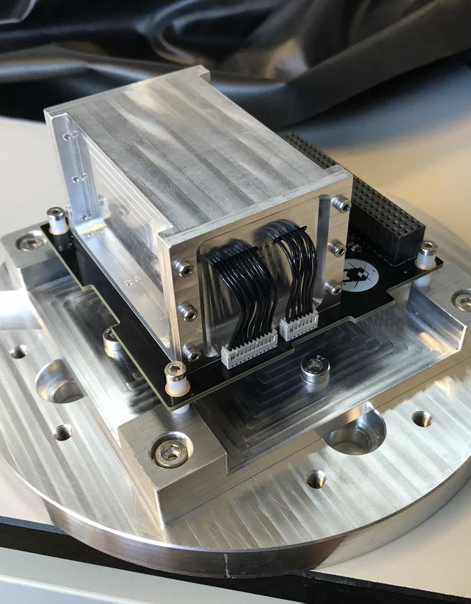
2                                                             David Murphy et al.

EIRSAT-1 mission. The detailed design and measurements to date demon-
strate the capability of GMOD in low Earth orbit, the scalability of the design
for larger CubeSats and as an element of future large gamma-ray missions.
Keywords Gamma-ray instrumentation · CubeSat · Gamma-ray bursts
PACS 95.55.Ka · 07.87.+v · 95.85.Pw

1 Introduction

Astrophysical sources of gamma-rays (considered here to cover the energy
range from tens of keV to several GeV) play an increasingly important role in
time domain and multi-messenger astronomy [1]. Gamma-ray bursts (GRBs)
produce their peak energies at several hundred keV, signposting the collapse
of massive stars and the mergers of neutron star binaries or neutron star-black
hole binaries [2, 3, 4, 5]. The short-lived gamma-ray transient, GRB 170817A,
was the first detected electromagnetic counterpart to a gravitational wave
source [6, 7, 8, 9]. This energy range is also key to a fuller understanding of
the processes operating in relativistic jet and outflow sources, nucleosynthesis
occurring in novae and supernovae, the physics of compact objects, and the
nature of dark matter [10, 11, 12].
    Many of the major gamma-ray satellites, including Konus-WIND [13], Swift
[14], INTEGRAL [15], Fermi [16] and AGILE [17], are mature missions in their
extended operations phase. The upcoming SVOM mission is designed primar-
ily to detect, localise and follow up GRBs and other high-energy transients
[18]. Einstein Probe is a forthcoming mission due to launch by the end of
2022 with wide-field x-ray monitoring and narrow-field x-ray follow-up ca-
pability, targeting transient astrophysical events [19, 20]. THESEUS [21] and
the Gamow Explorer [22] are mission concepts that focus on high redshift
gamma-ray bursts and time domain multi-messenger astronomy. THESEUS
was in contention for the fifth medium-class mission in ESA’s Cosmic Vision
programme but was not finally selected for implementation [23]. However, a
space instrument covering the relatively unexplored energy band from 100 keV
to several GeV, that would be a successor to the COMPTEL instrument on
the Compton Gamma-Ray Observatory in the 1990’s [24], has not yet been
implemented, despite numerous proposals [25, 26, 27, 28, 29, 30].
    One of the major technical challenges to be overcome to access this rel-
atively unexplored energy band with the required sensitivity is the need to
exploit both Compton scattering and pair creation in a single instrument,
which leads to significant mass and complexity in both hardware and on-
board software. Fast, high light-yield scintillators [31], new optical detectors,
such as silicon photomultipliers (SiPMs), and high-speed digital electronics,
all promise to greatly improve instrument performance while reducing mass
and complexity [32].
    High altitude balloons have long been used as test-beds for new space
technologies. The performance of a compact Compton telescope design, COSI,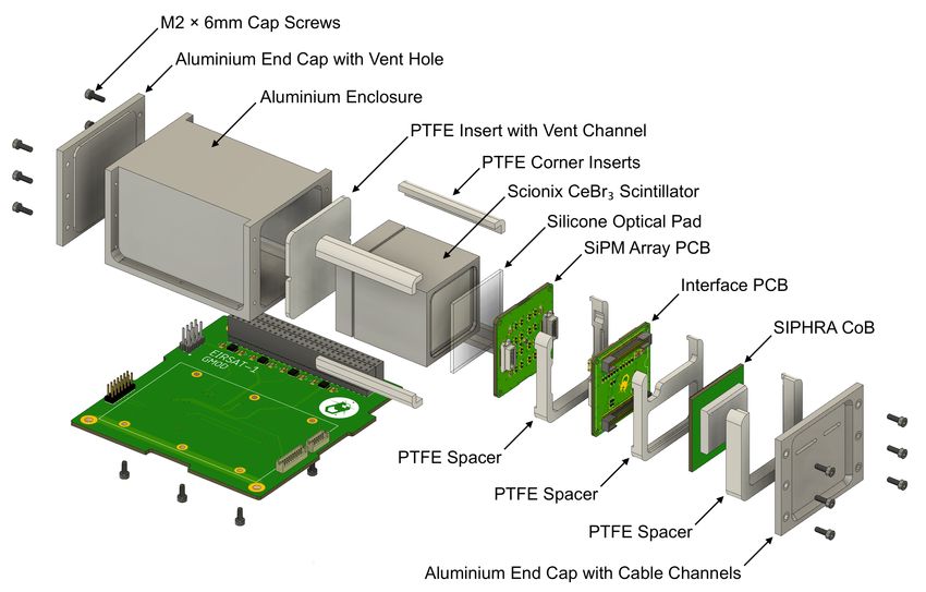
A compact instrument for gamma-ray burst detection on a CubeSat platform II     3

based on Germanium [33, 34] has been demonstrated on a balloon flight, as
has a Compton telescope based on SiPMs, with LaBr3 [35] and CeBr3 [36].
GAGG(Ce) and Lutetium Fine Silicate (LFS) scintillators paired with an
SiPM array and SIPHRA ASIC have been investigated for use in Compton tele-
scopes [37]. The US DoD Space Technology Programme has provided in-orbit
demonstration (IOD) of the compact SIRI instrument, combining an SiPM
array with an SrI2 scintillator and successors SIRI-2, GARI (using GAGG
scintillator) and Glowbug are in development [38, 39]. The technology readi-
ness level (TRL) of these new technologies has been advanced further with the
launch of the GECAM pair of micro-satellites in December 2020 which use a
hemispherical array of detectors composed of LaBr3 with SiPMs, to detect
GRBs and other transients [40].
    Nanosatellites (usually defined as having masses less than 10 kg) and Cube-
Sats (built from modular cubes, 10 cm on a side) are also being deployed as
platforms for IOD, accelerating the qualification cycle of new technologies for
space. In parallel to their usefulness for IOD, the capabilities of nanosatellites
for many branches of astrophysics, and for education, are of growing interest
[41, 42, 43, 44, 45, 46].
    Improving instrument performance, while reducing development time, cost
and complexity, are key enablers to ensuring the gamma-ray transient sky
remains under surveillance during gravitational wave (GW) observing runs.
Gamma-ray sensors on different nanosatellites in distinct orbits can provide
all-sky GRB detection and localisation capability, supporting observations by
larger missions and optimising the chances for discovery of electromagnetic
counterparts to GW sources. Several such missions that are currently under
study or being implemented include HERMES [47, 48], BurstCube [49, 50] and
GRBAlpha [51] for CAMELOT [52]. GRID is a student-led GRB CubeSat
network, the first of which was launched in 2018 [53]. The GRID GRB detector
is based on GAGG scintillator with SiPMs. IGOSAT is a student gamma-ray
3U CubeSat based on CeBr3 , scheduled for launch in late 2022 [54].
    This paper describes the CubeSat GRB detector, GMOD, and its incor-
poration as the main science payload in EIRSAT-1, the “Educational Irish
Research Satellite” which is planned to be Ireland’s first satellite [55]. GMOD
is a novel CubeSat payload in its use of CeBr3 with SiPMs. Section 2 briefly
outlines the evolution that has led to the current GMOD design. Sections 3
and 4 present the configuration of the detector assembly and the motherboard
in detail. Section 5 gives a comprehensive overview of both the TTE data
generated by GMOD, and the light-curves, spectra and triggers generated by
the on-board computer (OBC). The results of the laboratory characterisation
of GMOD are presented in Section 6 and these results are compared to the
performance of other CubeSat payloads in Section 7.
    A companion paper [56] presents the simulation study for GMOD, includ-
ing predicted effective area as a function of energy and off-axis angle, and
estimated GRB detection rates. The environmental qualification campaign is
described in [57].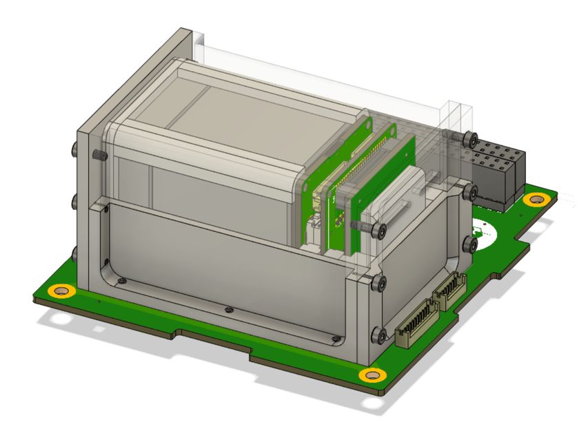
4                                                                  David Murphy et al.

Fig. 1 GMOD and its accommodation within the EIRSAT-1 stack. Left: The GMOD envi-
ronmental qualification model (EQM) comprising the aluminium-enclosed detector assembly
and the black motherboard PCB mounted on a test fixture. Right: GMOD in the EIRSAT-1
EQM. GMOD is in the aluminium housing near the top of the stack, indicated by the red
rectangle.

2 GMOD for EIRSAT-1

GMOD evolved from a prototype building block module for the pixellated
calorimeter of a full Compton-pair telescope. This gamma-ray detector (GRD)
[58] used a monolithic LaBr3 (Ce) crystal scintillator with an SiPM array, read
out by a low–power ASIC called ‘SIPHRA’ [59] (Section 3.3). The scintillator
was subsequently replaced by CeBr3 , due to its lower intrinsic background [60]
and the GRD was flown on a high-altitude balloon [61].

    In early 2017, the initial design for GMOD as a CubeSat payload was
developed as part of the student-led EIRSAT-1 mission concept [55], with much
of the architecture inherited from the GRD. The discovery of GW170817/GRB
170817A coincided with the approval of EIRSAT-1 by ESA’s educational Fly
Your Satellite! programme and motivated the additional requirement for GRB
detection. Figure 1 shows GMOD and its accommodation within the EIRSAT-
1 2U stack.

   The detector assembly (Sections 3) and the motherboard (Section 4) are
the two main elements of GMOD and are shown in the exploded view in
Figure 2.
A compact instrument for gamma-ray burst detection on a CubeSat platform II 5 Fig. 2 Exploded view showing the GMOD detector assembly above, and the CubeSat- compatible GMOD motherboard beneath. 3 Detector Assembly As shown in Figure 2, the GMOD detector assembly consists primarily of a scintillator, SiPM optical detectors, and the SIPHRA which is used to process and digitise the analog signals from the SiPMs, all contained within a light- tight enclosure. One of the advantages of using an ASIC like SIPHRA is that the readout electronics can be made sufficiently small to be included in the de- tector assembly (Figure 1), eliminating bulky harnesses to carry analog SiPM signals to the motherboard. Within the enclosure, the instrument is divided into two major sub-assemblies, the scintillator and an electronic stack. The latter comprises the SiPM array, SIPHRA, and an interface PCB which ties all of the electronics in the stack together and provides the harnessed interface to GMOD’s motherboard (Section 4). Figure 3 shows these two sub-assemblies inside the enclosure. 3.1 Scintillator GMOD uses a 25 × 25 × 40 mm 3 cerium bromide (CeBr3 ) crystal scintillator supplied by Scionix enclosed within a hermetically sealed unit (Figure 4). The hermetic enclosure has external dimensions of 33 × 33 × 43.8 mm 3 and is made of aluminium with a quartz window to allow the scintillation light to exit. The 2 mm thick quartz window is placed on one of the square 33 mm × 33 mm faces of the enclosure, exposing a 25 mm × 25 mm face of the CeBr3 crystal. The remaining five sides are wrapped with a PTFE light reflector.
6                                                                      David Murphy et al.

Fig. 3 Assembled configuration of GMOD showing the detector assembly attached to the
motherboard PCB. The light-tight enclosure of the detector assembly has been rendered
partially transparent to reveal the internal components. Inside the enclosure, the electron-
ics stack sub-assembly can be seen to the right of the scintillator. The detector assembly
measures 75 mm × 51 mm × 42 mm.

   The CeBr3 scintillator was selected for a number of reasons. CeBr3 has
similar performance characteristics to LaBr3 [62] but is available at a much
lower cost. CeBr3 does not suffer from the high intrinsic radiation of LaBr3
caused by decay of 138 La. The smaller 25 mm square cross-section of the CeBr3
crystal is well matched to the J-series SiPM array, which has an active area
extent of 25.06 mm × 25.06 mm.

3.2 SiPM Array

To measure the scintillation light produced by the crystal, GMOD uses six-
teen J-series 60035 SiPMs produced by SensL (now ON Semiconductor). The
J-series has a microcell fill factor of 75% and 22,292 microcells for the 6 mm
variants and a dark count rate of 50 kHz/mm2 . The J-series SiPM is available
in a through-silicon via (TSV) package with a Ball Grid Array (BGA) inter-
face. With a 35 µm microcell size, the active surface area of the J-series SiPM
spans 6.07 mm × 6.07 mm and is accommodated in the 6.13 mm × 6.13 mm
TSV package.
    The SiPMs are arranged on a custom 35 mm × 35 mm PCB using an auto-
mated pick-and-place process to produce a 4 × 4 array with a nominal 200 µm
spacing, matching the recommended value (Figure 4). This gives a total tiled
SiPM span of 25.12 mm × 25.12 mm while the active microcells within the full
array have an extent of 25.06 mm × 25.06 mm.
A compact instrument for gamma-ray burst detection on a CubeSat platform II 7
Fig. 4 Left: The CeBr3 crystal scintillator. Right: The J-series 4 × 4 SiPM array pictured
atop the detector assembly electronics stack. The interface PCB and SIPHRA ASIC can be
seen below the array separated by a series of supporting PTFE spacers.
The SiPM array is arranged in a common-anode configuration, with all
SiPM anodes being connected to a common negative bias supply via indepen-
dent low-pass filters consisting of a 51 Ω resistor and a 10 nF capacitor. The
filters are contained on the reverse side of the PCB which also has two Hi-
rose DF17 board-to-board connectors which provide the interface to the array.
The cathode of each SiPM is connected directly to the ASIC inputs via the
board-to-board connectors. The pinout of the board-to-board connections was
designed to be symmetrical so that it is permissible to attach the SiPM array
upside-down, removing a potential assembly error.
SiPM performance is affected by temperature, notably SiPM breakdown
voltage varies with temperature [63]. As SiPM gain is a function of the over-
voltage above breakdown at which the SiPMs are biased, this temperature
dependence of the breakdown voltage leads to an overall temperature depen-
dence for the instrument calibration. The reverse side of the SiPM array there-
fore contains a PT100 temperature sensor placed at the centre of the board to
measure the SiPM temperature. This sensor is digitised by the SIPHRA ASIC
(Section 3.3) each time the SiPM outputs are sampled allowing for periodic
adjustments to be made to the bias voltage (Section 4.1) or for appropri-
ate temperature-dependent calibration to be applied on the ground. While no
active thermal control is used to regulate the SiPM temperature, a passive
system is used to insulate the arrays from external temperature fluctuations.
as discussed in Section 3.5).
As part of the EIRSAT-1 critical design review, a thermal analysis of the
spacecraft was performed considering a number of scenarios for the planned
ISS-like orbit. The predicted SiPM temperatures for the planned ISS-like low8 David Murphy et al.
Typical, On
50 Typical, Off
Solstice, On
40 Solstice, Off
Temperature (°C)
30
20
10
0
0 2 4 6 8 10 12 14 16
Simulation Time (hours)
Fig. 5 The temperature of the SiPM array as predicted by the EIRSAT-1 thermal analysis
simulation. The typical and solstice cases for an ISS-like orbit are shown, both with (On)
and without (Off) the effects of power dissipation within the spacecraft. Note: the values
shown here carry uncertainties of ±10◦ C [64].
Fig. 6 Left: SIPHRA CoB top view showing the aluminium chip cover which protects the
silicon die. Centre: SIPHRA CoB underside. Right: Interface PCB. This side interfaces to
the SIPHRA CoB while the reverse side interfaces to the SiPM array and has the harness
connectors visible in Figure 4.
Earth orbit are shown in Figure 5. The initial conditions for the simulation set
the spacecraft temperature to 20◦ C and for a typical orbit, a quasi-equilibrium
SiPM temperature is reached between ∼31◦ C and ∼34◦ C. For an ISS-like orbit,
during the solstices, it is possible for the spacecraft to spend several days in
un-eclipsed sunlight. During this time the spacecraft temperature increases,
pushing the SiPM temperature to approximately 55◦ C, though with lower
variability due to the lack of thermal cycling. It should be noted that due
to the approximations involved in thermal modelling these values carry an
uncertainty of ±10◦ C [64].
3.3 SIPHRA
The SIPHRA (Silicon Photomultiplier Readout ASIC) [65] is used to read out
and digitise the analog pulses from the SiPM array (Figure 6). While SIPHRA
was developed by Integrated Detector Electronics AS (IDEAS) as a generalA compact instrument for gamma-ray burst detection on a CubeSat platform II 9
purpose readout IC for photon detectors, it was designed using the GRD’s
SiPM array as a reference. As GMOD’s array topology is identical to that
of the GRD, SIPHRA is therefore particularly well suited to this application.
SIPHRA was designed with with low-power considerations and with radiation
protections, including latch-up immunity, single event upset mitigation and
error correction which have been verified by radiation hardness testing [66].
SIPHRA has sixteen channels for SiPMs and an internal seventeenth sum-
ming channel which provides a sum of the sixteen inputs. The SIPHRA analog
front-end is described in Section 3.3.1. Control and configuration of SIPHRA
(Section 3.3.2) is achieved through a series of registers accessed by a Serial
Peripheral Interface (SPI).
SIPHRA operates at 3.3 V and has three power nets (digital, analog, and
I/O) which are supplied by separate low-drop-out voltage regulators on the
GMOD motherboard. SIPHRA requires an external 80 µA constant reference
current to generate internal biases. This reference current is generated by a
constant-current source on the GMOD motherboard (Section 4).
3.3.1 SiPM Analog Frontend
As GMOD uses a common-anode SiPM array, it can utilise SIPHRA’s current
mode input stages (CMIS) which work with negative charge and allow for
a range of input attenuation from −16 nC to −0.4 nC. Each channel’s CMIS
is connected to a current comparator and to a charge comparator and pulse
height spectrometer via a current integrator. This setup is replicated for the
summing channel, which is connected to all sixteen CMIS. The trigger thresh-
olds of the comparators are configured using a series of 8-bit DACs and a
configurable hold unit allows any or all of the comparators to trigger readout
of the spectrometer as well as indicating the trigger type and channel for each
readout.
The pulse height spectrometer consists of a pulse shaper, a track & hold
circuit, and an output multiplexer to SIPHRA’s ADC. When a trigger occurs,
a hold is asserted on all channels allowing the ADC to digitise each channel
in turn. The same ADC is used to digitise the SiPM array temperature with
each trigger using the PT100 mounted on the reverse of the array.
3.3.2 Control and Data Interfaces
Trigger data from SIPHRA is output using a serial interface which operates
at the 1 MHz input clock rate. The serial output is controlled by a readout
controller which waits for a hold that is either generated internally by any of
the enabled comparators, externally via SPI command, or with the dedicated
hold input connected to the GMOD motherboard. The controller then digitises
enabled channels in sequence. The digitised pulse height values are combined
with a series of trigger flags and channel IDs, serialised, and transmitted to
the GMOD motherboard from the serial output.10 David Murphy et al.
Various logic-level inputs and outputs are provided for direct interfacing to
certain features. GMOD utilises the external hold input and the error output.
The external hold input is used to generate external triggers for baseline noise
determination. The error output indicates if any of SIPHRA’s configuration
register parity checks have an error which signals an error in the registers
potentially caused by a single event upset.
3.4 Interface PCB Design
The interface PCB (Figure 6) uses the Chip-on-Board (CoB) version of
SIPHRA which is wire-bonded to a PCB, but is contained on a 32 mm × 32 mm
PCB produced by IDEAS with two 50-pin header connectors. SIPHRA CoB
is provided as a socketed component requiring no difficult processes, such as
wire-bonding, to integrate it with the custom electronics. Although this ver-
sion of SIPHRA requires more volume than other versions (e.g. BGA), making
its accommodation within the GMOD detector assembly more challenging, it
significantly reduces assembly complexity.
The detector assembly interface PCB therefore acts as a three-way inter-
face between the SiPM array, the SIPHRA CoB package, and the GMOD
motherboard. The PCB measures 35 mm × 35 mm to match the size of the
SiPM array PCB and couples directly to the rear of the array using Hirose
DF17 board-to-board connectors matching those on the array. The reverse side
features two Samtec FTM board-to-board to match the SIPHRA CoB inter-
face, resulting in a small detector assembly electronics stack of three PCBs,
as shown in Figure 2.
The connection to the GMOD motherboard is achieved through two small
harnesses. An 11-pin connection is used to carry digital signals while a 7-pin
connection is used for power connections. Both harnesses use Hirose DF13
connections which are extensively used in the EIRSAT-1 spacecraft. The digi-
tal connection carries the following: two ground lines; the external hold input,
which externally triggers ADC readout; the error output signal, which in-
dicates a parity error in the configuration registers; reset; SPI configuration
interface; the 1 MHz system clock input and the 1 MHz serial data output. The
power connection carries two ground lines, the 80 µA constant reference cur-
rent, 3.3 V supply for the three SIPHRA supply nets, and the SiPM negative
bias voltage.
Various passive electronic components required to support SIPHRA, such
as decoupling capacitors, pull-up resistors and input protection resistors, are
also included on the interface PCB.
3.5 Enclosure
The GMOD detector assembly is contained within an aluminium light-tight
enclosure which physically supports the assembly components and preventsA compact instrument for gamma-ray burst detection on a CubeSat platform II 11
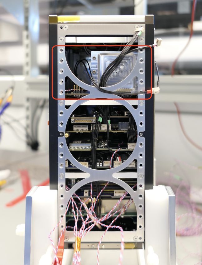
Fig. 7 Left: The CeBr3 crystal scintillator held securely within the aluminium enclosure
by the four PTFE corner spacers. Right: The aluminium enclosure with all internal detector
assembly components installed. The SIPHRA CoB can be seen in the centre surrounded by
one of the PTFE spacers which supports it.
any external light from reaching the SiPMs. The enclosure has external di-
mensions of 75 mm × 51 mm × 42 mm and is mounted directly to the GMOD
motherboard as shown in Figures 2 & 3.
The design of the enclosure takes account of the requirement to protect
the delicate scintillator crystal, particularly during launch. For strength, the
GMOD enclosure is made from Aluminium 6082, the same material as the
CubeSat structure. The enclosure is essentially a square-tube-like structure
(Figure 1) with flanges to allow the attachment of two end-caps and to allow
mounting of the detector assembly to the motherboard. The two openings are
necessary to achieve a good surface finish along the full length of the bore by
machining from both ends of the enclosure while also providing a convenient
disassembly mechanism as the detector assembly components can be pushed
clear through the enclosure. The internal clear cross section of the enclosure
has dimensions of 38 mm × 38 mm with 3.5 mm diameter rounded corners.
To fully constrain the scintillator and prevent it from moving during launch,
it is securely held within the enclosure by four 2.5 mm thick PTFE corner
inserts which can be seen in Figure 7. A 2 mm thick PTFE insert is placed
at the back of the scintillator which includes a serpentine venting channel
leading to a 1 mm hole in the end-cap at that end of the enclosure. This
provides sufficient air evacuation capacity for the volume inside the enclosure
while also preventing light ingress.
The detector assembly electronic stack comprising the SiPM array, the
SIPHRA ASIC, and the interface PCB are also supported within the alu-
minium enclosure by PTFE spacers which match the internal profile of the
enclosure. A series of spacers which are machined to match the contours and
features of the PCBs are placed between each PCB in the stack and between
the PCBs and the enclosure end-cap. The harnesses from the interface PCB
to the motherboard are routed along slots in the spacers and through cable12 David Murphy et al.
channels machined into the end-cap. The PCB spacers and the harness routing
can be seen in Figures 4 & 7.
A silicone optical pad is used as an interface between the scintillator win-
dow and the SiPMs. These pads are suitable for use in a vacuum and are
slightly deformable. The dimensions of the PTFE spacers and the enclo-
sure are designed such that as the end-caps are installed, the silicone pad
is slightly compressed achieving good optical coupling and securing all com-
ponents within the enclosure.
The PTFE spacers also serve to insulate the internal components from the
enclosure. Combined with the relatively large thermal mass of the scintillator,
the spacers result in internal temperatures which are more stable against exter-
nal fluctuations. This functionality was demonstrated during thermal vacuum
testing of the GMOD instrument [57]. During temperature slews, the tem-
perature of the internal components, measured at the SiPM array and at the
aluminium side wall of the scintillator hermetic housing, was seen to signifi-
cantly lag behind that of the enclosure which was in direct contact with the
TVAC chamber’s thermal plate. In flight, the temperature fluctuations are ex-
pected to be even further attenuated as the temperature of the internal stack
components will lag behind that of the spacecraft exterior.
4 GMOD Motherboard
The GMOD Motherboard is a CubeSat PC-104 compatible PCB which hosts
the support electronics necessary to operate the detector assembly. It includes
a micro-controller, responsible for data collection, and a CPLD for interfacing
to SIPHRA’s serial data output. An SPI flash memory allows the data to be
cached in GMOD before being sent to the spacecraft on-board computer.
The motherboard also hosts the power conditioning for the detector as-
sembly including the adjustable bias PSU which generates the negative bias
voltage required by the SIPM array. Separate linear voltage regulators are pro-
vided for each of SIPHRA’s power rails, resulting in a stable low-noise power
supply. The 80 µA constant reference current required by SIPHRA is provided
by an adjustable constant current source based on a reference implementation
from Texas Instruments [67] with component values adjusted to match the
desired output range.
A block diagram illustrating the functions of GMOD is shown in Figure 8.
The motherboard conforms to the de facto standard for CubeSat com-
ponents popularised by the Pumpkin Inc. CubeSat Kit, measuring 90.17 mm
× 95.89 mm and interfacing to EIRSAT-1’s main system bus through a pair of
Samtec ESQ-126-39-G-D stack-through headers. The motherboard is shown
in Figure 9.
The board has been designed with the majority of its components on the
underside thereby allowing the 75 mm × 51 mm detector assembly to be bolted
directly to the top of the board. The system bus interface header carries I2 C,
serial, PPS, and other logic signals between GMOD and the OBC. PowerA compact instrument for gamma-ray burst detection on a CubeSat platform II 13
Motherboard Detector Assembly
VDDIO DVDD AVDD
5V 3.3V 3.3V 3.3V
3.3V
SIPM
Array
3.3V VBatt DC/DC V-
Power
Power
V-
CSK Header - Spacecraft Interface
16 Channels
Flash Constant
Memory DAC Current Constant
Current
PPS
SPI
SPI
SPI SPI
Serial GPIO GPIO
Digital
Digital
Micro- SIPHRA
I2C Serial Clock Clock
Controller
GPIO Reset Serial Serial
CPLD
JTAG
JTAG MUX JTAG
Fig. 8 Block diagram of the GMOD motherboard and detector assembly showing the con-
nections between components. Green indicates a major functional component, orange indi-
cates power supply nets and grey indicates a physical connector interface.
Fig. 9 The GMOD motherboard. The majority of the components are accommodated on
the bottom of the board (left) allowing the detector assembly to be bolted to the top of the
board (right).
from the Electrical Power System (EPS) is also provided to GMOD via this
header. The motherboard has four other connectors, two of which are used for
connection to the detector assembly as detailed in Section 3 and two JTAG
connections which are used to reprogram the micro-controller and the CPLD.14 David Murphy et al.
4.1 Bias PSU
The bias power supply unit (PSU) is designed to provide an adjustable bias
voltage between −25 V and −28.3 V suitable for the SiPM array.
The bias PSU is based on the MAX629 DC-DC converter from Maxim
Integrated, operated in an inverting boost mode, providing an output that
is both negative and greater in magnitude than the input voltage. The DC-
DC converter is supplied by a switchable EPS channel at the battery voltage
which is dedicated to GMOD. The suitable range of the PSU is determined
by the SiPM breakdown voltage and the desired SiPM gain which is related
to the over-voltage above breakdown at which the SiPMs are biased. The
SensL J-series SiPMs have a breakdown voltage of approximately 24.5 V and
for GMOD, an appropriate gain is found at an over-voltage of approximately
3 V, leading to a nominal SiPM bias voltage of −27.5 V as the array is reverse
biased.
An adjustable output is necessary to either maintain a consistent gain by
compensating for calibration drift in the PSU and for the effect of tempera-
ture on the SiPM breakdown voltage which varies by 21.5 mV/° C [63], or to
adjust the gain if desired. The output of the DC-DC converter is adjustable by
biasing the DC-DC converter’s feedback with a voltage generated by a Texas
Instruments DAC7562T Digital-to-Analog Converter which allows for 1.2 mV
increments.
The output of the bias PSU is monitored by the micro-controller at two
points using the 12-bit ADC channels of the micro-controller. The first is the
PSU feedback bias voltage at the DAC output which is monitored directly,
while the second is the output of the PSU which is scaled through an amplifier
to convert the PSU’s output range of −25 V to −28.3 V to between 0 V and
3.3 V.
4.2 Complex Programmable Logic Device
The serial stream (Section 3.3.1) requires programmable logic to efficiently
parse. The serial output from SIPHRA is an unusual format featuring 20-
bit words and inverted idle, start, and stop conditions when compared to a
standard serial interface. It is therefore not compatible with any standard
peripheral interface available on a micro-controller.
As the logic needed is relatively simple, a Xilinx CoolRunner XC2C256
Complex Programmable Logic Device (CPLD) was chosen as it provides the
required functionality with low power consumption. GMOD utilises the CPLD
to process the SIPHRA serial data before transmitting a simplified data stream
to the micro-controller using a standard serial interface. The CPLD also gen-
erates the external 1 MHz clock signal which operates the readout controller.
The SIPHRA readout controller transmits digitised signals as a series of
20-bit words, one for each channel which is readout during a trigger. The word
format includes a 5-bit channel ID, 3 bits of trigger information, and the 12-A compact instrument for gamma-ray burst detection on a CubeSat platform II 15
bit ADC value for the channel. The CPLD reads this serial data using custom
receiver logic, parses the channel ID and packs the trigger information and the
ADC value into two bytes. The CPLD is also responsible for timestamping,
determining a ‘finetime’ value in microseconds which is disciplined by a PPS
input from the OBC. This timestamp is generated when channel 0, the first
channel for each trigger, is received from SIPHRA. The CPLD separates the
individual SiPM channels (Ch1–16) from the array temperature (Ch0) and the
summed channel (Ch17) and transmits them separately in two packet types
to the micro-controller. The packet types are prepended with a different 2-
byte attached synchronisation marker (ASM) to allow the micro-controller to
identify and appropriately processs their contents.
The individual, or ‘16-Channel’ packet contains the ASM, timestamp, and
the trigger flags and ADC values for the 16 individual SiPM channels. The
summed packet contains the ASM, timestamp, and the trigger flags for the
summed SiPM channel and the array temperature. The data volume can be
reduced by disabling readout of channels 1–16 on SIPHRA which the CPLD
will recognise and only transmit the summed packet to the micro-controller.
The CPLD includes a JTAG programming interface that is connected via
a multiplexer to both the micro-controller and a header with a standard Xil-
inx pinout. This configuration allows the CPLD to be reprogrammed on the
ground and in-flight.
4.3 Micro-controller
A Texas Instruments MSP430FR5994 micro-controller operates all periph-
eral functions of GMOD and serves as the interface between the payload and
the OBC. This micro-controller was selected based on power and radiation-
tolerance considerations. The ‘FR’ range of MSP430 micro-controllers use Fer-
roelectric Random Access Memory (FRAM) which stores data in the electric
polarity of a PZT (lead zirconate titanate) film and is highly tolerant to radi-
ation effects.
The micro-controller is connected to the OBC via the main system bus
header. The connections include an I2 C interface to a dedicated payload I2 C
bus, a serial connection with bootstrap loader (BSL) support, and OBC GPIOs
which are used to reset the micro-controller and invoke the BSL for reprogram-
ming in flight. A JTAG programming interface is provided on the board for
on ground reprogramming. The I2 C interface operates as a command interface
through which the OBC controls GMOD while the serial interface is primar-
ily used to bulk transfer data collected by GMOD to the OBC for in-flight
processing, storage, and downlink to the ground [68].
Using the peripheral hardware on the motherboard, the micro-controller
is responsible for data collection and management, control of SIPHRA and
control of power components.16 David Murphy et al.
4.3.1 Data Collection and Management
The micro-controller accepts event data generated by SIPHRA which has been
preprocessed and formatted by the CPLD. The event data is asynchronous,
being generated in response to gamma-ray detection events in the detector,
and is received by the micro-controller using a standard serial receiver.
The micro-controller sorts the event data based on the ASM type which
is attached by the CPLD and stores the events in 256-byte data units which
are prepended with a coarse time-stamp corresponding to the mission-elapsed
time. The complete data units are then both transmitted to the OBC and
stored in the GMOD SPI flash. The SPI flash implements a circular buffer
which acts as a backup as well as a cache which allows the event data rate to
temporarily exceed the GMOD to OBC data rate. The OBC can either request
specific data units from the SPI flash or command GMOD to transmit data
units as soon as they are available.
4.3.2 Control of SIPHRA
While event data from SIPHRA is read using a serial UART via the CPLD,
control and configuration of SIPHRA is achieved through an SPI interface
which allows SIPHRA’s configuration registers to be programmed. The regis-
ter values are first loaded by the OBC into the micro-controller where they are
buffered and then may be transferred to SIPHRA upon command. SIPHRA
implements a hardware parity check on these registers to indicate if the con-
tents may have been corrupted by a single event upset (SEU). The error out-
put on SIPHRA is connected to a GPIO on the micro-controller allowing a
pin change interrupt to immediately detect an SEU at which point the micro-
controller can reload the correct register values from the buffer.
4.3.3 Control of Power Components
As detailed in Section 4.1, the bias voltage of the SiPM array is controlled and
monitored by the micro-controller. The control of the bias voltage is achieved
via an SPI connected DAC which produces a voltage which influences the DC-
DC converter’s feedback input. The monitoring of the bias voltage is through
two feedback channels, one directly from the DAC and one which is scaled
from the array voltage, into two of the micro-controller ADC inputs.
As the gain of the SiPM array varies with both temperature and bias volt-
age, the bias voltage can be adjusted in order to compensate for temperature
variations. The temperature of the array is read out by SIPHRA with each
event. Based on the temperature of the SiPM array, the voltage feedback and
the desired detector gain, the micro-controller periodically calculates the cor-
rect DAC value to achieve the appropriate SiPM bias voltage.
The constant-current source on the motherboard which is used by SIPHRA
as a reference current is also adjustable via voltage input. The DAC used
to adjust the bias voltage is a dual channel DAC and its second output isA compact instrument for gamma-ray burst detection on a CubeSat platform II 17
utilised to allow micro-controller control of the reference current allowing for
calibration to be performed without adjusting component values.
5 Data Handling
Data handling responsibilities for GMOD are shared between the motherboard
[69] and EIRSAT-1’s OBC. GMOD produces data in the form of time-tagged
events (TTEs, Section 5.1) which are considered the canonical GMOD data-
type from which science data should be generated on the ground. EIRSAT-1
uses a UHF downlink operating at a 9600 baud and while multiple ground
stations are envisaged, the mission feasibility has been conducted assuming a
single ground station. This single station, depending on the orbit, limits con-
tact with EIRSAT-1 to several communication windows per day, each of which
are each on the order of 10 minutes [70, 71]. Over several contact windows, an
average total daily contact time of approximately 29 mins is available which is
sufficient to downlink 2 MB of data. During nominal operations, approximately
1.5 MB of this data can be allocated to GMOD. To reduce the bandwidth,
the OBC performs on-board generation of secondary data products, includ-
ing light-curves (Section 5.2.1), spectra (Section 5.2.2), and event-rate triggers
(Section 5.2.3), all based on TTEs from the summed SIPHRA channel. The
total light-curve and spectral data utilisation are configuration dependent, but
at a very conservative estimate will generate less than 450 kB per day, giving
a remaining daily data budget of ∼1 MB for the downlink of TTEs. Based
on the predicted in-orbit background rate described in [56], the data gener-
ation rate for TTEs from the summed SIPHRA channel is estimated to be
approximately 30 MB per day. It is therefore possible to downlink many but
not all generated TTEs for ground processing with a single station. Since the
housekeeping needs of the spacecraft and downlink of GMOD secondary data
products are met by a single ground station, TTE downlink can be improved
with the provision of additional stations.
For each ground station, the downlink windows are clustered, with sev-
eral occurring each one orbit apart, followed by large gaps of approximately
18–20 hours during which downlinking is not possible. With multiple ground
stations, the distribution of contact windows becomes more complicated and
is dependent on the geographical location of the stations. As it will be diffi-
cult to locate ground stations in such a way that large gaps in contact will be
eliminated, the operations strategy has been planned to accommodate these
gaps and clustered communication windows. During the first window, the sec-
ondary data products will be downlinked first to determine which TTEs should
be scheduled for downlink for the remainder of the communication time in the
cluster. At the start of each following communication window, new secondary
data products which have been generated during the orbit will be downlinked
in order to adjust the TTE downlink priority, for example if TTEs associated
with a new trigger have become available.18 David Murphy et al.
SIPHRA Channel
Channel Trig
T Flag
Number Type
ADC Value
SIPHRA
1 5 2 12
0 8 16 20
SIPHRA Event
Ch 0 Ch 17
Ch 1 Ch 2 Ch 16
(Temp) (Summed)
T Flag
Trig
Pad
Type
ADC Value
1 1 2 12
0 1 2 4 16
GMOD 16-Ch Format (x16)
CPLD
T Type
Fine Time Ch 1 Ch 2 Ch 16 Fine Time TTE Counter Summed Ch ADC Temperature ADC
32 16 16 16 32 7 1 12 12
0 32 48 64 272 288 0 32 39 40 52 64
16-Channel TTE Summed TTE
MCU
Coarse Time TTE 1 TTE 2 TTE 7 Coarse Time TTE 1 TTE 31 Checksum
32 288 288 288 32 64 64 32
0 32 320 608 1760 2048 0 32 96 1952 2016 2048
16-Channel Page Summed Page
Log Time Row ID Page 1 Page 16 Log Time Row ID Page 1 Page 16
32 32 2048 2048 32 32 2048 2048
0 32 64 2112 30784 32832 0 32 64 2112 30784 32832
16-Channel Row Summed Row
OBC
Row 0 Row 1 Row 2 Row n Row 0 Row 1 Row 2 Row n
32832 32832 32832 32832 32832 32832 32832 32832
16-Channel Storage Channel Summed Storage Channel
Fig. 10 The data-flow of time-tagged events indicating the data structures and formats
used by each component in the processing chain. Events are generated by SIPHRA in the
detector assembly, are time-tagged by a CPLD and processed by an MSP micro-controller
on the GMOD motherboard before being transferred to EIRSAT-1’s OBC for downlink to
the ground and generation of secondary data products.
During large communication window gaps, timely notification of triggers
will still be communicated to the community by incorporating the most re-
cent trigger information into EIRSAT-1’s beacon which is broadcast from the
spacecraft at regular intervals, as fast as once per 30 s depending on battery
levels. The beacon format will be publicly available allowing it to be received
and decoded on the ground using amateur radio equipment or inexpensive
software defined radios. A hosted server will allow received beacon data to be
submitted and made publicly available. It is anticipated that larger community
initiatives such as SatNOGS [72] will help to collate and publish EIRSAT-1
beacon data.
The support of the amateur radio community will be sought to downlink
additional EIRSAT-1 data. While this is complicated by the need to manage
the downlink using cryptographically signed uplink commands, the EIRSAT-1
ground segment has been planned to allow communication through trusted
suitable third-party ground stations, including amateur stations.
Figure 10 illustrates the data flow between GMOD components with a
representation of the data structures utilised during each step. GMOD dataA compact instrument for gamma-ray burst detection on a CubeSat platform II 19
originates as event data in SIPHRA which is then fine-time-tagged and for-
matted by the CPLD, becoming separate ‘16-channel’ and ‘summed-channel’
TTEs before being transferred to the micro-controller. The micro-controller
sorts and packages multiple TTEs along with a 4-byte coarse-timestamp into
256-byte long data units referred to as ‘pages’, a term inherited from the small-
est writable data unit used by GMOD’s flash memory. Each summed-channel
page holds 31 TTEs while a 16-channel page holds just 7 TTEs. The coarse-
timestamps are measured in seconds and are used to resolve the ambiguity
of the TTE’s finetime which overflows approximately every 71 minutes. The
16-channel and summed-channel pages are then each cached by the micro-
controller in both a circular buffer implemented in the flash memory and
a FIFO buffer implemented in the micro-controller random access memory
(RAM). Pages are then transferred from GMOD to the OBC typically in an
automatic ‘streaming’ mode, but may also be manually requested. In stream-
ing mode, the OBC sets a ready flag when it has finished processing data,
indicating to GMOD that it may transmit the next page when it becomes
available. In this mode, pages are typically taken from the RAM FIFO but
when high event-rates occur this FIFO may not be large enough and the pages
will instead be taken from the flash circular buffer until the backlog has been
cleared. Manually requested pages are retrieved based on their page address
within the flash.
The pages received by the OBC are then stored in data storage channels
on the OBC’s error detecting and correcting flash memory. Storage channels
are a feature of OBC software [68] which is written using Bright Ascension’s
Flight Software Development Kit [73]. The storage channels are data structures
which consist of a fixed number of rows, each of which have a fixed width.
Each row begins with the mission-elapsed-time at which it was saved and an
incrementing absolute row ID. As the pages are transferred to the OBC, the
summed TTEs are processed to generate the light-curves, spectra, and triggers,
which are also saved to their own data storage channels.
The OBC’s storage channels may be either ‘circular’ or ‘linear’. Circular
storage channels are used for most GMOD data-types and are written to one
row at a time with the newest rows overwriting the oldest rows when the
channel is full. This is useful for storing the most recent data without requiring
any data management. Required data simply has to be downlinked to the
ground before it is overwritten. In contrast, linear storage channels are heavily
write protected but require extensive data management. Like circular channels,
linear channels are also written to one row at a time but can no longer be
written to when full. Individual rows cannot be deleted so in order to free up
space in a linear channel the contents of the entire channel must be deleted.
Linear channels are used to store a backup of TTEs associated with triggers
(Section 5.2.3) to ensure that they are are not overwritten by newer data
even if they cannot be downlinked in a timely manner. Downlinking of all
GMOD data-types to the ground is performed by requesting a range of rows
from a particular storage channel which causes EIRSAT-1 to initiate a Large20 David Murphy et al.
Data Transfer (LDT) compliant with the European Coordination on Space
Standardization (ECSS) LDT service [74].
5.1 Time-Tagged Events
As described in Section 3.3, for each gamma-ray event SIPHRA produces eigh-
teen 12-bit ADC values encapsulated in eighteen 20-bit words also containing
trigger flags and channel number. The eighteen words correspond to array
temperature (channel 0), SiPM channels 1–16, and the summed SiPM channel
(channel 17) in that order. Upon receipt of channel 0, the CPLD records a 4-
byte fine-timestamp in microseconds which it then combines with trigger flags
and ADC values from SIPHRA to produce two time-tagged event data-units
with distinct formats, one for summed-channel data and one for 16-channel
data.
The summed-channel TTEs are considered the most important data type
as these will primarily be used for science while 16-channel TTEs are pri-
marily for verification of the instrument’s ability to perform individual SiPM
readout, a feature which will be important in future detectors which require in-
teraction localisation. The summed-channel TTEs carry a sequential counter
added by the CPLD to ensure that no events have been dropped from the
micro-controller or OBC processing chain. They are also more optimised for
downlink by bit-packing, a process of concatenating the bits from several val-
ues which do not fully fill an integer number of bytes and then packing every 8
bits into a byte with no respect to the value boundaries, rather than padding
each individual value to fill an integer number of bytes. The summed-channel
TTEs consist of the 4-byte fine-timestamp, a 7-bit sequence counter, a 1-bit
readout flag indicating that the event was ‘internally’ generated in SIPHRA
by a gamma-ray event rather than externally generated by a forced readout,
the 12-bit ADC value for the summed channel, and the 12-bit ADC value for
the SiPM array temperature resulting in each summed-channel TTE being 8
bytes long.
The 16-channel processing is comparatively simpler, resulting in less space-
efficient TTEs but which retain more triggering information which is useful
for evaluation of the instrument. Each 20-bit word corresponding to channels
1–16 has the 5 bits which indicate the channel number removed, resulting in
15 bits which are padded and packed into 2 bytes. Channels are readout in a
known order so the channel number is unnecessary. The 15 bits consist of a 1-
bit indicator that the individual channel was above readout threshold, a 2-bit
indicator of readout type (internally generated, externally generated by the
hold input, externally generated by SPI command), and the 12-bit ADC value
for the channel. The full 16-channel TTE contains the 4-byte fine-timestamp
followed by the sixteen 2-byte channel values for a total of 36 bytes per 16-
channel TTE.
The formats of both TTE types are summarised in Figure 10.A compact instrument for gamma-ray burst detection on a CubeSat platform II 21
5.2 Light-curves, Spectra, and Triggers
Once the TTE data has been transferred to the OBC it is available for fur-
ther on-board processing. The GMOD component of the on-board software
processes the summed TTE data to generate light-curves, spectra, and trig-
ger data-types. Once generated, all of the data-types are saved to respective
storage channels allowing for downlink.
5.2.1 Light-curves
The light-curve data-type records the number of counts over a configurable en-
ergy range in adjustable time bins. The light-curve precision can be configured
by setting the number of milliseconds for each bin. The data-type consists of
the light-curve epoch, bin duration, and uint16 values representing the number
of counts in each bin. The full light-curve row format is detailed in Figure 11.
Epoch -
Epoch - MET Bin-size
Log Time Row ID (s)
Fractional
(ms) Bin 1 Bin 2 Bin 120
(ms)
32 32 32 16 16 16 16 16
0 32 64 96 112 128 144 160 2032 2048
Light-curve Row
Fig. 11 GMOD light-curve data format.
5.2.2 Spectra
The spectrum data-type records the number of counts in discrete energy bins
over an adjustable period of time. GMOD produces TTEs containing 12-bit
ADC values for photon energy giving 4096 possible energy bins. The on-board
generated spectrum data-type re-bins these values into adjustable energy bins
beginning at a configurable ADC value and each containing a configurable
integer number of ADC values between 1 and 16. The data-type consists of
the spectrum epoch, integration time, ADC value of the first bin, bin width,
and uint16 values representing the number of counts in each bin. The full
spectrum row format is detailed in Figure 12.
Bin-size (ADC)
Epoch - MET Integration Start bin
Log Time Row ID (s) Time (s) (ADC) Bin 1 Bin 2 Bin 3 Bin 240
32 32 32 16 12 4 16 16 16 16
0 32 64 96 112 124 128 144 160 176 3952 3968
Spectrum Row
Fig. 12 GMOD spectrum data format.22 David Murphy et al.
5.2.3 Triggers
One of the most important data-types for ascertaining interesting GMOD data
is the trigger data. Triggers are generated by calculating the ratio of two mov-
ing averages of counts within a certain energy range in order to estimate the
current gamma-ray signal significance which is compared against a predefined
significance trigger level. The durations of the ‘signal’ window, ‘background’
window, and a background window delay can be tuned and reconfigured in-
flight. The intention is that the signal average represents the current gamma-
ray flux and that the background average represents the current gamma-ray
background. The background window length is of the order of several tens
of seconds and a delay of 10–20 s excludes the most recently detected counts
reducing an over-estimation of background for long GRBs. Appropriate signal
window lengths can vary for different sources so multiple trigger configurations
will be processed in parallel with signal windows ranging from several tens of
milli-seconds to several seconds.
In order to simplify the on-board algorithm for calculating the moving av-
erages, they are not true instantaneous averages recalculated for the arrival
of each gamma-ray photon but instead implemented as a series of time bins
of short duration (i.e. 8 ms) which are summed to reach the signal and back-
ground durations.
When the significance level exceeds the trigger level, a number of impor-
tant steps are carried out by the OBC. Firstly, a trigger data-type is generated
containing the trigger time, duration and peak significance of the burst, pro-
tected storage channel index, a trigger spectrum, and a trigger light-curve.
The full trigger format is detailed in Figure 13. The protected storage channel
index refers to a linear write-protected storage channel into which summed
TTEs for a configurable time before and after the trigger are saved by the
OBC. Finally, the trigger data is incorporated into EIRSAT-1’s beacon for
immediate transmission to potential receivers on the ground.
Spectrum
Trigger Time
Channel
Trigger Time
Storage
Duration Significance
Bin-size (ADC)
Log Time Row ID MET Fractional
(ms) (milli-sigma)
Start bin Spectrum Spectrum
(s) (ms) (ADC) Bin 1 Bin 2
32 32 32 16 32 16 8 12 4 16 16
0 32 64 96 112 144 160 168 180 184 200 216
Trigger Row
Light-curve
Spectrum Pre-trigger Bin Size Light-curve Light-curve Light-curve
Bin 120 (ms) (ms) Bin 1 Bin 2 Bin 120
16 16 16 16 16 16
2088 2104 2120 2136 2152 2168 4040 4056
Fig. 13 GMOD trigger data format.A compact instrument for gamma-ray burst detection on a CubeSat platform II 23
6 Detector Resolution
Following assembly of the engineering qualification model (EQM) of GMOD,
four gamma-emitting radioactive nuclides were used to characterise the detec-
tor calibration and resolution: Americium-241, Caesium-137, Sodium-22 and
Cobalt-60. Measurements of the sources were made one at a time and sources
were integrated for various durations depending on the source activity. This
duration was typically around 30 minutes, though in the case of the weaker
60
Co source the integration time was 90 minutes. Figure 14 shows the un-
calibrated spectra of the four nuclides processed from summed-channel TTEs
recorded by GMOD. The spectra presented are essentially raw, with the down-
linked data-set having been filtered only to ensure that all contributing events
were internally generated by the GMOD detector assembly. No re-binning has
been applied and no baselines have been subtracted.
250k 40k
² ¹Am 59 keV
¹³ Cs 32 keV
200k 30k
150k
Counts
20k
100k ¹³ Cs 662 keV
50k 10k
0 0
0 500 1000 1500 2000 2500 0 500 1000 1500 2000 2500
25k 5k
Co 1173 keV
4k
²²Na 511 keV
Co 1332 keV
20k
15k 3k
Counts
²²Na 1275 keV
10k 2k
5k 1k
0 0
0 500 1000 1500 2000 2500 0 500 1000 1500 2000 2500
ADC Value ADC Value
Fig. 14 Uncalibrated spectra of 241 Am, 137 Cs, 22 Na, and 60 Co measured using GMOD’s
summed-channel. The summed-channel combines the signals from all SiPMs prior to digiti-
sation and is the primary data which will be used during in-flight operation. Several spec-
troscopic lines have been fit as indicated to determine a calibration for the detector in this
mode.
The main spectral lines from each nuclide were fitted to determine their
centre position. The lines were fitted using a model consisting of a Gaus-
sian curve to model the detector broadened mono-energetic emission line and
a quadratic function to account for contributions from background and non-
photo-peak measurements of higher energy lines. A calibration for the detector
was determined by fitting the known energy of the lines as a quadratic func-
tion of the measured centre position ADC value. Figure 15 shows an example24 David Murphy et al.
Table 1 Spectral line widths as measured using summed-channel data from GMOD.
Nuclide Energy (keV) δE (keV) FWHM(%)
241 Am 59.541 4.0 15.9
137 Cs 32.061 4.1 29.7
137 Cs 661.657 15.3 5.4
22 Na 511 13.5 6.2
22 Na 1274.53 22.3 4.1
60 Co 1173.237 20.6 4.1
60 Co 1332.501 22.0 3.9
calibrated spectrum of a mixed test source containing 241 Am, 137 Cs, and 60 Co
processed based on this calibration from summed-channel TTEs recorded by
GMOD.
4000
² ¹Am 59 keV
3500
3000
¹³ Cs 662 keV
2500
Counts
2000
Co 1173 keV
Co 1332 keV
1500
1000
500
0
0 200 400 600 800 1000 1200 1400
Energy (keV)
Fig. 15 Calibrated spectrum of a mixed test source containing 241 Am, 137 Cs, and 60 Co
measured using summed-channel data from GMOD.
Having calibrated the detector, the spectral lines from the four nuclides
were refit in energy space to measure their widths and determine the detector
spectral resolution. The width of the Gaussian component of the fit gives the
1σ width of the line in energy, also called δE. The full width at half maximum
(FWHM) detector resolution for a given energy, E, is calculated as 2.35 times
δE expressed as a percentage of that energy. The resolution of the detector at
each of the measured spectral lines is given in Table 1.
The values for the detector resolution were fit using the model
p
δE = a2 + b2 E + c2 E 2 , (1)
which is adapted from [75]. The coefficient a is a constant term representing
limiting electronic resolution which is not expected to be an issue for scintil-
lation detectors and is therefore set to zero in the fit. The b term is propor-
tional to the square root of the energy, representing statistical fluctuations in
the number of charge carriers which in turn is related to fluctuations in theYou can also read