A 3D Printing Hexacopter: Design and Demonstration - arXiv
←
→
Page content transcription
If your browser does not render page correctly, please read the page content below
A 3D Printing Hexacopter: Design and Demonstration
                                                                                         Alexander Nettekoven1 and Ufuk Topcu2

                                           Abstract— 3D printing using robots has garnered significant
                                        interest in manufacturing and construction in recent years. A
                                        robot’s versatility paired with the design freedom of 3D printing
                                        offers promising opportunities for how parts and structures
                                        are built in the future. However, 3D printed objects are still
                                        limited in size and location due to a lack of vertical mobility of
                                        ground robots. These limitations severely restrict the potential
arXiv:2103.02063v1 [cs.RO] 2 Mar 2021

                                        of the 3D printing process. To overcome these limitations, we
                                        develop a hexacopter testbed that can print via fused deposition
                                        modeling during flight. We discuss the design of this testbed
                                        and develop a simple control strategy for initial print tests. By
                                        successfully performing these initial print tests, we demonstrate
                                        the feasibility of this approach and lay the groundwork for
                                        printing 3D parts and structures with drones.

                                                               I. INTRODUCTION
                                           3D printing has fundamentally changed the way 3D parts
                                        and structures are designed and produced [1]. The design
                                        freedom and the convenience of printing 3D objects directly                    Fig. 1.      The 3D printing hexacopter just finished printing a square
                                        from computer-aided design are just a few advantages that                      contour on top of a gray box. A video of this print test can be found
                                                                                                                       at https://youtu.be/tEooDpE2TyE.
                                        have been continuously leading to fundamental changes in
                                        established processes of these industries, e.g., the printing
                                        of houses [1], [2], [3], [4]. Recent work has focused on
                                                                                                                       successfully performing initial print tests, we lay the ground-
                                        combining robotics with 3D printing as the versatility of
                                                                                                                       work to print entire 3D parts and structures in future work.
                                        robots can improve the printing of medium to large-scale
                                                                                                                       Successful printing may not only provide insights for 3D
                                        objects [1], [2], [3], [4], [5]. However, a lack of vertical mo-
                                                                                                                       printing applications with drones but also for other manufac-
                                        bility and sometimes horizontal mobility for ground robots
                                                                                                                       turing applications with drones that require surface contact
                                        still significantly limits the 3D printing of these objects [6],
                                                                                                                       or close to ground operations.
                                        [2], [5].
                                           At the same time, rapid advancements in control and                            We structure the remainder of the paper as follows. In
                                        autonomy of drones are driving the exploration of new                          Section II, we provide a brief overview of related robotics
                                        drone applications in manufacturing and construction that                      work in manufacturing and construction. In Section III, we
                                        go far beyond already established surveillance and mapping                     detail the design of the 3D printing hexacopter. Section IV
                                        applications [7], [8]. Prominent examples are pick-and-place                   details the control strategy for achieving the desired printing
                                        tasks similar to robotic arms and surface inspections that                     task. In Section V, we present and discuss the first successful
                                        require close proximity to objects of interest during flight [7],              prints with the 3D printing hexacopter. Finally, we provide
                                        [8], [9]. Unlike ground robots and manufacturing machines,                     our conclusions and discuss the next steps in Section VI.
                                        drones have the advantage of being unrestricted in 3D
                                        space and are more capable of reaching remote locations.                                            II. RELATED WORK
                                        A merger of 3D printing and drone technology has the                              Numerous robotic testbeds have demonstrated the success-
                                        potential to overcome these limitations and fundamentally                      ful combination of 3D printing with robots; a selection of
                                        enhance the way 3D objects are built for the manufacturing                     these systems and their printing capabilities can be found
                                        and construction industries [7], [10].                                         in recent surveys for manufacturing and construction [3],
                                           In this paper, we develop a hexacopter testbed that can                     [4], [5], [6], [2]. Notable examples include the multi-robot
                                        print simple contours on a build surface while flying. By                      printing system by [11] or the 3D printing system by [12].
                                          1 Alexander Nettekoven is with the Walker Department of Mechanical           Another example is a climbing 3D printer system that can
                                        Engineering at the University of Texas at Austin, 204 E. Dean Keeton Street,   scale its printed structures to continue printing in the vertical
                                        Austin, Texas 78712, USA nettekoven@utexas.edu                                 direction [13]. These systems provide promising solutions for
                                          2 Ufuk Topcu is with the Faculty of the Department of Aerospace
                                                                                                                       printing large 3D objects. However, these systems are still
                                        Engineering and Engineering Mechanics at the University of Texas
                                        at Austin, 2617 Wichita Street, Austin, Texas 78712-1221, USA                  restricted in 3D space and depend on the structural integrity
                                        utopcu@utexas.edu                                                              of the 3D printed objects.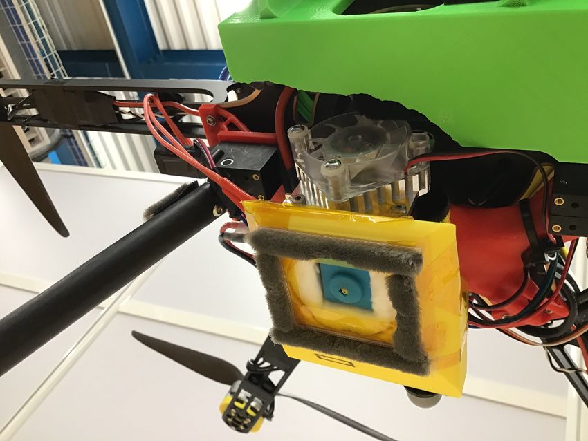
To overcome these limitations, initial work by [14] inves-      surface, the extruded material will be less likely to deposit
tigated the combination of a quadcopter with 3D printing           at the desired location on the surface. This larger distance
by using a syringe-like depositing apparatus for different         could adversely affect the printing accuracy or even cause the
polymer materials. These materials were in a highly viscous        deposited material to fly away due to the turbulent air from
liquid form and were deposited by the quadcopter from a            the hexacopter. In FDM printers, this distance is usually less
considerable distance to the surface. The deposited material       than a millimeter.
covered large areas of the surface, including areas beyond            Second, the extruder nozzle should not touch the surface
the desired printing location. Due to the large spread of the      as the surface might damage the nozzle and vice versa.
deposited material, this approach was not able to print 3D         Ideally, the distance between the nozzle and build surface
objects with distinct shapes. Recent work by [15] investi-         stays constant to ensure uniform printing. However, since
gated different materials that could be used for a similar         the hexacopter is flying close to the build surface, turbulent
depositing setup as [14]. Though the authors identify suitable     air from the build surface can pose significant challenges to
materials for different applications, the depositing apparatus     keeping a tight, constant distance to the build surface.
still suffers from the same limitations as [14].                      Third, the FDM hotend uses high temperatures to melt
                                                                   the printing material. Proper insulation of the hotend is
                   III. DRONE DESIGN
                                                                   essential to prevent the hotend from losing too much heat
   The goal of the hexacopter testbed is to deposit material       from the circulating air and to prevent the surrounding
with high positional accuracy. In other words, the hexacopter      hexacopter parts from possible damage. Finally, to minimize
should be able to move to a desired location and deposit           the hexacopter’s total weight, any parts added should be
material precisely at that location. Since hexacopters have        lightweight while still being sturdy enough to minimize
less positional accuracy than robotic arms or other 3D             vibrations during flight.
printing machines and also have a considerable amount of
vibrations, the hexacopter design plays a critical role in         C. Flight platform
achieving this goal. For designing a 3D printing hexacopter,
                                                                      Several commercial flight platforms already exist to carry
we first discuss which 3D printing process is used and why.
                                                                   larger payloads, such as the equipment necessary for 3D
Based on this 3D printing process, we derive several design
                                                                   printing. However, the integration of the mechatronic equip-
objectives that guide the design of the different submodules.
                                                                   ment and the desire to have full access to the underlying
A. Selection of 3D printing process                                control algorithms make building a custom-built flight plat-
                                                                   form for the testbed a better option.
   Fused deposition modeling (FDM) is the most popular
                                                                      The core of the 3D printing hexacopter is taken from a DJI
3D printing technology and is commonly used in desktop
                                                                   F550 ready-to-fly kit and consists of a top and bottom plat-
3D printers [16]. FDM offers several advantages, such as
                                                                   form. The core is at the geometric center of the hexacopter
affordability, wide material choice, and the simplicity of
                                                                   and carries the flight electronics, the 3D printing equipment,
the technology. The main components of the FDM printer
                                                                   and the batteries. Attached to the core are six custom arms
consist of a hotend that heats the desired printing material, an
                                                                   that have been extended to accommodate larger motors than
extruder that pushes the material out of the extruder nozzle,
                                                                   the standard F550 motors. The motors are mounted on 3D
and a mechanism that moves the FDM printer along a desired
                                                                   printed mounts that have a dihedral angle of eight percent.
surface. Furthermore, the FDM process uses a thinner fila-
                                                                   This dihedral angle increases the hexacopter’s stability and
ment than concrete printing, predominantly used in related
                                                                   significantly reduces vibrations caused by complex airflow
work. A thinner filament allows for finer printing quality
                                                                   interactions between the propellers and the ground, also
and thus, a potentially better analysis of the movement
                                                                   called ground effects [17]. Fig. 2 shows an overview of the
mechanism of the 3D printer. In addition to these advantages,
                                                                   testbed.
the FDM process is similar to other nozzle-based 3D printing
processes and even non-3D printing processes that have a              The flight electronics consist of a Pixhawk 4 flight
distinct tool tip similar to a nozzle. These similarities could    controller loaded with the open-source software PX4. The
give a testbed the potential to be used for other applications     flight controller is connected to an onboard ODROID-XU4
if desired and can make the 3D printing results relevant for       computer that uses ROS and Wifi to communicate with an
applications beyond 3D printing. Due to these advantages,          external laptop. The onboard computer also feeds position
the FDM technology is picked for the 3D printing hexacopter.       and velocity measurements from a VICON motion capture
We use polylactic acid (PLA) as the printing material due to       system to the flight controller. Section IV provides details
its ease-of-use for printing.                                      on the control of the hexacopter.

B. Design objectives                                               D. 3D printing apparatus
   Based on the selected 3D printing process, we derive              The 3D printing apparatus consists of the extruder, the
several design objectives. First, the nozzle needs to be close     hotend, the printing material, the circuitry powering and
to the build surface for optimal extrusion and adhesion to         controlling the printing process, and the nozzle guard. We
the build surface. If the hexacopter is too far from the build     describe the different components in the next paragraphs.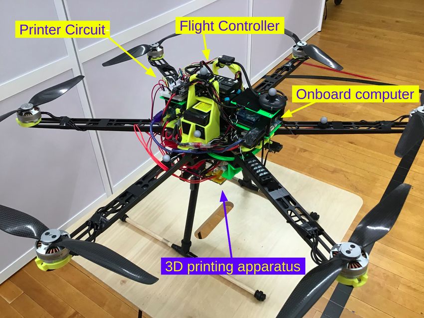
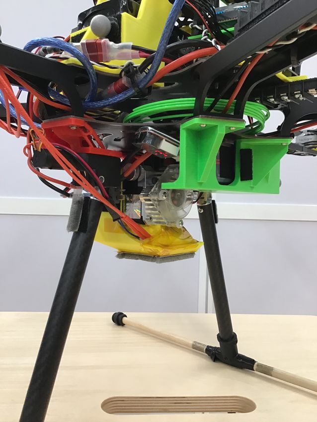
(a) 3D printing apparatus     (b) Nozzle guard from below

                                                                        Fig. 4. Close-up of the 3D printing apparatus and the nozzle guard. The
                                                                        hexacopter touches the surface with the nozzle guard and uses the nozzle
                                                                        guard to slide across the build surface.

Fig. 2. Top view of the 3D printing hexacopter. The main electronic
                                                                        nozzle (yellow part in Fig. 4(a)). The hexacopter uses the
components of the testbed are labelled.                                 nozzle guard to touch the build surface and slide across the
                                                                        surface. While sliding, the nozzle prints through a hole in
                                                                        the nozzle guard as shown in Fig. 4(b). The distance will be
                                                                        nearly constant as long as the hexacopter does not deviate
                                                                        much from the upright position during printing.
                                                                           In addition to guaranteeing a nearly-constant distance to
                                                                        the build surface, the nozzle guard also significantly impacts
                                                                        the goal of printing with high positional accuracy. By creat-
                                                                        ing friction between the nozzle guard and the build surface,
                                                                        the hexacopter is more robust to disturbances from ground
                                                                        effects and general inaccuracies in the position control.
                                                                        The more friction the hexacopter has with the surface, the
                                                                        fewer the disturbances that need to be compensated for
                                                                        by the motors. However, if there is too much friction, the
                                                                        hexacopter needs to use more effort to slide during printing.
Fig. 3. Front view of the 3D printing hexacopter. The main components   To prevent hard surface contact, we install thin weather
for 3D printing are labelled.                                           striping underneath the nozzle guard.
                                                                           The nozzle guard also accommodates ceramic fiber in-
                                                                        sulation that insulates the hotend from the surrounding air
   For the extruder and hotend, we use an E3D Titan Aero                flow. Insulating the hotend makes the heating of the hotend
print head that combines both components in a compact                   more efficient, preserving battery power. Furthermore, the
form. The hotend of this print head is capable of reaching              insulation protects the nozzle guard from melting as the
temperatures up to 285 ◦ C. We use a 1 mm diameter for the              nozzle guard is out of the same PLA material the 3D printing
hotend’s nozzle and attach the print head to the bottom of the          hexacopter uses to print.
flight platform with 3D printed connectors. These connectors
are designed with generative design to find a sturdy solution           E. Balancing the hexacopter
that can withstand potential ground impacts during testing                 It is well known that for position accuracy and stability
while also being light enough to reduce the hexacopter’s                purposes the horizontal location of a drone’s center of mass
weight.                                                                 should coincide with its geometric center. We design the
   For storing the 3D printing material, we use the space               testbed with this requirement in mind by distributing the
between the top and bottom platforms of the hexacopter                  weight evenly across the platform. However, since the 3D
(see Fig. 3). We feed the printing material through a hole              printing hexacopter uses parts with different masses, the
in the bottom platform to the print head. The printing circuit          center of mass is still off from the geometric center. To
that controls the 3D printing equipment has its own battery,            balance the hexacopter, we iteratively adjust counterweights
which is located underneath the hexacopter next to the print            along the hexacopter’s arms until the horizontal location of
head. Controlling the print head only requires an Arduino               the center of mass aligns with the geometric center.
Uno as well as several basic electronic components, such as
transistors and stepper drivers.                                                         IV. CONTROL STRATEGY
   The above components are already sufficient for 3D                      Before we can test the designed testbed, we need to
printing. However, given the design objectives, we cannot               develop a control strategy for sliding across the build surface.
guarantee that the nozzle will not touch the build surface              To perform initial print tests, we focus on keeping the control
during printing or that the nozzle’s distance to the surface            strategy simple and easily tunable. This approach will allow
will be constant, even with advanced control algorithms.                us to observe the behavior of the 3D printing hexacopter and
Thus, we design a nozzle guard that surrounds the extruder              modify the controller during the experiments.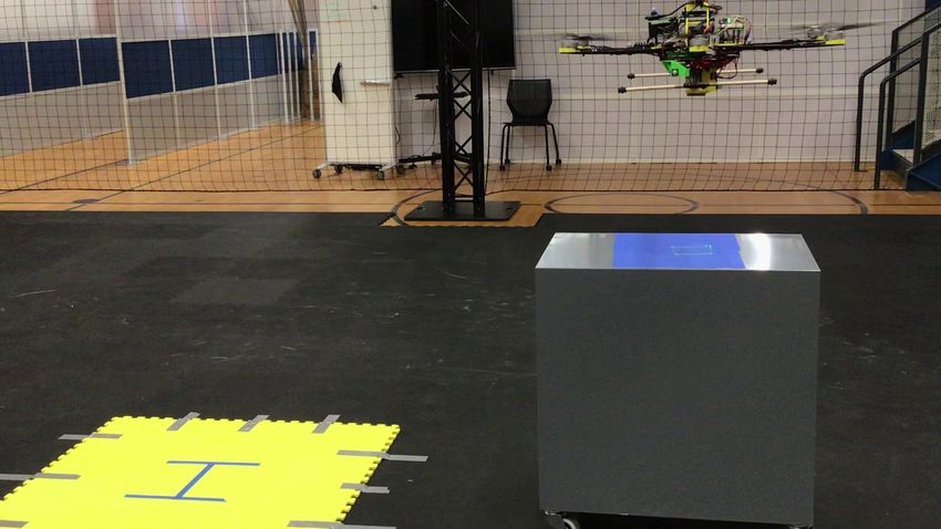
Commanded T hrust [%]
As mentioned in Section III, the hexacopter is designed
to slide across the surface. Since the build surface acts
48
as a support in the vertical direction, we can separate the
controller design for the horizontal and vertical directions.
We first discuss the horizontal position controller and then 46
follow with a thrust controller for the vertical direction.
These controllers are activated once the hexacopter reaches 44
the build surface. 40 50 60 70 80 90 100
A. Horizontal position controller V oltage P ercentage [%]
To control the horizontal position of the 3D printing
Fig. 5. Cubic function used for updating the commanded thrust during
hexacopter, we use a simple PID position controller that printing. For the experiments of this paper, we replace the battery at roughly
outputs roll and pitch commands to the PX4 flight stack. The 40 percent remaining voltage.
yaw is always zero. PX4 then converts the attitude commands
to motor outputs through its internal control structure [18].
The pitch angle at time step k is calculated with respect to hexacopter might be in its upright position, but the flight
the fixed world frame of the motion capture system by controller may estimate the roll and pitch to be somewhere
0 around ±1 degrees. This offset stems from the IMU calibra-
αlim + βθ if θ [k] ≥ αlim + βθ
tion of the hexacopter and can usually be ignored as the offset
θ[k] = βθ − αlim if θ0 [k] ≤ βθ − αlim (1) is relatively small compared to the commanded attitudes in
0
θ [k] otherwise, free flight. However, since we are using small angles to
control the sliding motion during 3D printing, this offset can
where αlim is an attitude limit, and βθ is a tuned parameter
significantly impact the horizontal position controller.
that accounts for errors in the attitude estimation. θ0 [k] is
calculated by the modified PID controller Though it is possible to reduce this offset by iteratively
tuning the parameters for PX4, the calibration process is
θ0 [k] = Kp,θ ex [k] + Ki,θ ix [k] + Kd,θ dx [k] + βθ , (2) tedious. The calibration requires iterations of taking off, ob-
serving the hexacopter’s flight behavior, landing, and recal-
with the individual terms given by
ibrating the parameters with slight hardware modifications.
ex [k] = xd [k] − xm [k] (3) Yet, these iterations may still not eliminate the offset. Thus,
we use βφ and βθ to account for this offset.
ix [k] = ix [k − 1] + ∆t ex [k] (4) Finding βφ and βθ is straightforward; we let the hexa-
copter hover a few meters above the ground to eliminate any
ex [k] − ex [k − 1] ground effects and then command the hexacopter to have
dx [k] = . (5)
∆t zero roll, pitch, and yaw. If there is an offset, the hexacopter
Here, ∆t is the time difference between updates of the posi- will start moving towards the corresponding direction. We
tion controller, and Kp,θ , Ki,θ , and Kd,θ are the proportional, change the commanded angles iteratively until the hexacopter
integral, and derivative gains, respectively. xd [k] and xm [k] no longer drifts from its starting position. These angles are
are the desired setpoint and the measured position in the x- then used as bias for the horizontal position controller.
axis of the world frame. For the experiments of this paper, the
world frame uses the east-north-up convention. To calculate B. Thrust controller
the roll angle, we use the same equations but with a flipped
sign for the calculated angle, the measured position ym [k] in An important assumption for the horizontal position con-
the y-direction, and the desired setpoint yd [k]. troller is that the friction between the nozzle guard and the
Compared to a regular PID controller, the above controller build surface stays roughly constant. Since the PID gains
features several modifications. First, αlim ensures that the depend on this friction, a drastic change in friction can
hexacopter stays close to the upright position. Staying close result in instabilities of the hexacopter or the hexacopter
to this equilibrium position keeps the distance between the not moving at all. To keep constant friction, one could send
nozzle and the build surface nearly constant. αlim also pre- a constant thrust command to PX4, which will result in
vents any drastic maneuvers that could cause a crash during constant RPMs of the motors. However, due to the voltage
printing. For the experiments of this paper, αlim has a value drop of the battery, the RPMs would continuously decrease,
of five degrees. Second, we use ramping setpoints to generate increasing the friction as a result.
smooth printing motions and prevent the position controller To counter this voltage drop during printing, we update the
from saturating. At each time step, the current setpoint is commanded thrust to PX4 based on the remaining voltage
updated towards the commanded printing destination based percentage. The remaining voltage percentage is calculated
on the allowed sliding speed during printing. by
Finally, we use βφ and βθ to account for a constant Vmeasured − Vmin
offset in the attitude estimation from the actual attitude. The Vremaining = 100 · ,
Vmax − Vmin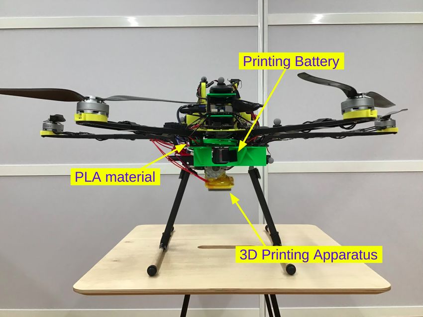
where Vmeasured is the measured voltage, Vmax is the volt-
age of the fully-charged battery, and Vmin is the minimum
voltage still considered safe for the battery. The voltage
of a lithium polymer battery usually decreases quickly at
the beginning of a discharging cycle and then continues to
decrease at a slower pace until the voltage is beyond the
usual operating range. To roughly account for this behavior,
we update the commanded thrust based on a cubic function
plotted in Fig. 5. The commanded thrust is significantly
reduced at the start when the battery is fully charged and
then quickly reaches a point where the thrust stays relatively
constant.                                                                          (a) 3D printed contour of a square.

           V. EXPERIMENTAL EVALUATION
  In this section, we experimentally evaluate the 3D printing
hexacopter. We first discuss the printing procedure and then
present the experimental results. We conclude this section
with a discussion of the results and the 3D printing hexa-
copter concept.
A. Printing procedure
   To demonstrate the hexacopter’s printing capabilities, we
print simple contours on the surface of a box. The box’s
designated printing area is covered with blue printer tape
to increase adhesion with the PLA material. At the start of
each printing experiment, the hexacopter automatically flies
to the box and descends until the nozzle guard touches the
build surface. Once the hexacopter makes contact, we switch             (b) 3D printed letters ”UT”, short for University of Texas.
from the PX4 position controller to the horizontal position
                                                                 Fig. 6. Simple contours printed by the 3D printing hexacopter on blue
controller from Section IV. To traverse the desired path, we     printer tape.
sequentially update the position controller’s setpoints to the
contours’ corner coordinates. While the hexacopter moves
across the surface, the 3D printing apparatus continuously       largely due to the nozzle guard. From running multiple
deposits material onto the build surface.                        consecutive print tests, the nozzle guard also proves to
B. Results                                                       properly shield the hotend, allowing it to maintain a constant
                                                                 temperature of 250 ◦ C while protecting the nozzle from
   We demonstrate the hexacopter’s capability to successfully
                                                                 ground contact.
3D print by presenting two examples of the printed contours
                                                                    The corners of the printed contours exhibit unwanted
in Fig. 6. The first contour is a square with side lengths
                                                                 clumps of PLA material. These clumps are a result of
of 10 cm. The second contour exhibits the letters ”UT”. The
                                                                 the hexacopter waiting for a new corner setpoint while
printed contours show that the deposited PLA materials stick
                                                                 the 3D printing apparatus continued to deposit material. A
to the surface and can withstand the turbulent air from the
                                                                 consequence of these clumps is the curved vertical line in the
hexacopter. We provide a video showing the successful print
                                                                 ”T” letter of the second printed contour. As the hexacopter
of the square contour. 1
                                                                 moved across the surface, the top clump of the vertical line
   Based on the position measurements from the motion
                                                                 was dragged to the left by the weather stripping underneath
capture system, the hexacopter’s overall position accuracy is
                                                                 the nozzle guard.
approximated to be ±1 cm in the horizontal directions. This
tolerance is especially noticeable when the hexacopter starts    C. Discussion
the sliding motion or reaches the desired corner setpoint.
However, once the hexacopter starts sliding, the accuracy           The initial printing results demonstrate the feasibility of
appears to be significantly better.                              combining 3D printing with drones as the hexacopter testbed
   From visual inspections of the printed contours, we notice    can print simple contours on the build surface. However,
that the edges feature relatively uniform material deposition    since the 3D printing hexacopter is a novel testbed, several
and minimal variation within the straight lines. These results   limitations still need to be addressed to improve the current
indicate that the hexacopter successfully maintains a constant   printing capabilities. First, a trajectory tracking algorithm for
and tight distance between the nozzle and the build surface,     simultaneously controlling the hexacopter’s movement and
                                                                 printing is required to eliminate the observed PLA clumps.
  1 https://youtu.be/tEooDpE2TyE                                 Second, the current position accuracy needs to be further
quantified. Based on this quantification, the accuracy can [6] B. Nematollahi, M. Xia, and J. Sanjayan, “Current Progress of 3D
be improved by developing advanced control algorithms Concrete Printing Technologies,” 06 2017.
[7] O. Maghazei and T. Netland, “Drones in manufacturing: Exploring
customized for the 3D printing process. Finally, the complex opportunities for research and practice,” Journal of Manufacturing
interactions of the nozzle guard and the ground need to be Technology Management, vol. Forthcoming, 09 2019.
investigated further. [8] A. Baturone, G. Heredia, A. Franchi, G. Antonelli, K. Kondak,
A. Sanfeliu, A. Viguria, J. R. Martinez-de Dios, F. Pierri, J. Cortés,
In addition to these immediate improvements, general A. Santamaria, M. Soto, R. Balachandran, J. Andrade Cetto, and
questions about the concept of a 3D printing drone may arise. Á. Rodrı́guez Castaño, “The AEROARMS project: Aerial robots with
For example, a drone can only stay in the air for a limited advanced manipulation capabilities for inspection and maintenance,”
IEEE Robotics & Automation Magazine, vol. PP, pp. 1–1, 08 2018.
amount of time and carry a limited amount of 3D printing [9] F. Augugliaro, S. Lupashin, M. Hamer, C. Male, M. Hehn, M. W.
material. However, a tethered setup for power and material Mueller, J. S. Willmann, F. Gramazio, M. Kohler, and R. D’Andrea,
supply are promising options to ensure continuous printing. “The Flight Assembled Architecture installation: Cooperative con-
struction with flying machines,” IEEE Control Systems Magazine,
Though a tethered setup may limit a drone’s flexibility, vol. 34, no. 4, pp. 46–64, 2014.
the tethered connection can be easily modified to fit the [10] P. Latteur, S. Goessens, J.-S. Breton, J. Leplat, Z. Ma, and C. Mueller,
desired end-application. This modification allows the drone “Drone-Based Additive Manufacturing of Architectural Structures,” 08
2015.
to maintain its flexibility and advantage over robotic arms or [11] X. Zhang, M. Li, J. H. Lim, Y. Weng, Y. W. D. Tay, H. Pham, and
other 3D printing machines for large-scale objects. Another Q.-C. Pham, “Large-scale 3D printing by a team of mobile robots,”
question may address the hexacopter’s dependency on the Automation in Construction, vol. 95, pp. 98–106, 2018.
[12] C. Gosselin, R. Duballet, P. Roux, N. Gaudillière, J. Dirrenberger, and
nozzle guard. When building objects in the vertical direction, P. Morel, “Large-scale 3D printing of ultra-high performance concrete
the nozzle guard will quickly lose contact with the ground. – a new processing route for architects and builders,” Materials &
However, a modified nozzle guard design, similar to wall- Design, vol. 100, pp. 102–109, 2016.
[13] M. Vélez, E. Toala, and J. C. Zagal, “Koala 3D: A continuous climb-
climbing robots, may maintain the nozzle guard’s func- ing 3D printer,” Robotics and Computer-Integrated Manufacturing,
tionality by using the previously printed object or another vol. 64, p. 101950, 2020.
close-by object as support. Furthermore, dependencies on the [14] G. Hunt, F. Mitzalis, T. Alhinai, P. A. Hooper, and M. Kovac, “3D
printing with flying robots,” in 2014 IEEE International Conference
nozzle guard may be reduced by advanced control algorithms on Robotics and Automation (ICRA), 2014, pp. 4493–4499.
customized for the 3D printing process. [15] B. Dams, S. Sareh, K. Zhang, P. Shepherd, M. Kovac, and R. J. Ball,
Overall, we demonstrate the feasibility of combining 3D “Aerial additive building manufacturing: three-dimensional printing
of polymer structures using drones,” Proceedings of the Institution of
printing with drones by successfully performing initial FDM Civil Engineers - Construction Materials, vol. 173, no. 1, pp. 3–14,
print tests. In doing so, we lay the groundwork to overcome 2020. [Online]. Available: https://doi.org/10.1680/jcoma.17.00013
limitations in size and location for 3D printed parts and [16] T. Wohlers. Popularity of FDM. [Online]. Available: https://
wohlersassociates.com/blog/2016/01/popularity-of-fdm/
structures. [17] H. Efraim, A. Shapiro, and G. Weiss, “Quadrotor with a Dihedral
Angle: on the Effects of Tilting the Rotors Inwards,” Journal of
VI. CONCLUSIONS Intelligent & Robotic Systems, vol. 80, pp. 313–324, 2015.
Parts built by 3D printing robots or other 3D printing [18] PX4 Autopilot. (2021, 02) Controller diagrams. [Online].
Available: https://docs.px4.io/master/en/flight{ }stack/controller{ }
machines are usually limited in size or location by the 3D diagrams.html
printer. To overcome these limitations, we built a hexacopter
testbed that can deposit material on a build surface via
a 3D printing process called fused deposition modeling.
With the goal of printing with high positional accuracy, we
discussed the hexacopter’s design and developed a simple
control strategy for 3D printing while flying. We successfully
performed initial print tests by printing simple contours on
a build surface. In doing so, we demonstrated the feasibility
of our approach. Future work will focus on the investiga-
tion of advanced control algorithms to further improve the
hexacopter’s printing accuracy.
R EFERENCES
[1] K. Wong and A. Hernandez, “A Review of Additive Manufacturing,”
ISRN Mechanical Engineering, vol. 2012, 08 2012.
[2] F. Bos, R. Wolfs, Z. Ahmed, and T. Salet, “Additive manufacturing
of concrete in construction: potentials and challenges of 3D concrete
printing,” Virtual and Physical Prototyping, vol. 11, pp. 1–17, 08 2016.
[3] A. Paolini, S. Kollmannsberger, and E. Rank, “Additive manufacturing
in construction: A review on processes, applications, and digital
planning methods,” Additive Manufacturing, vol. 30, p. 100894, 2019.
[4] S. H. Ghaffar, J. Corker, and M. Fan, “Additive manufacturing tech-
nology and its implementation in construction as an eco-innovative
solution,” Automation in Construction, vol. 93, pp. 1–11, 2018.
[5] N. Labonnote, A. Rønnquist, B. Manum, and P. Rüther, “Additive con-
struction: State-of-the-art, challenges and opportunities,” Automation
in Construction, vol. 72, pp. 347–366, 2016.You can also read