2022-23 Design, Build, Fly Rules - AIAA
←
→
Page content transcription
If your browser does not render page correctly, please read the page content below
2022-23 Design, Build, Fly Rules

Summary
The AIAA through the Applied Aerodynamics, Aircraft Design, Design Engineering and Flight Test Technical
Committees and the AIAA Foundation invites all university students to participate in the Textron
Aviation/Raytheon Missiles & Defense - Student Design, Build, Fly Competition. The contest will provide a real-
world aircraft design experience for engineering students by giving them the opportunity to validate their
analytic studies.
Student teams will design, fabricate, and demonstrate the flight capabilities of an unmanned, electric powered,
radio controlled aircraft that can best meet the specified mission profile. The goal is a balanced design
possessing good demonstrated flight handling qualities and practical and affordable manufacturing
requirements while providing a high vehicle performance.
To encourage innovation and maintain a fresh design challenge, the design requirements and performance
objectives are updated for each new contest year. The changes provide new design requirements and
opportunities, while allowing for application of technology developed by the teams from prior years.
Check the rules package carefully as items and approaches that were legal in past years may not be legal for
this contest year. Only the contents of this year's Rules package along with the current FAQ and Q&A
documents hold bearing on the requirements and/or allowances for the current contest year.
NOTE: Items in the rules that are critical to the safety and execution of the competition or are new are hi-
lighted in RED text. Please take note of these requirements and rules.
It is the responsibility of the teams to know and follow all provided rules, the FAQ and Q&A, and all contest day
briefings.
Cash prizes are $3000 for 1st, $2000 for 2nd and $1500 for 3rd place. The winning team may be invited to
present their design at AIAA’s AVIATION Forum. The team with the best Report Score will receive a $100 prize
from the Design Engineering Technical Committee.

                                                        1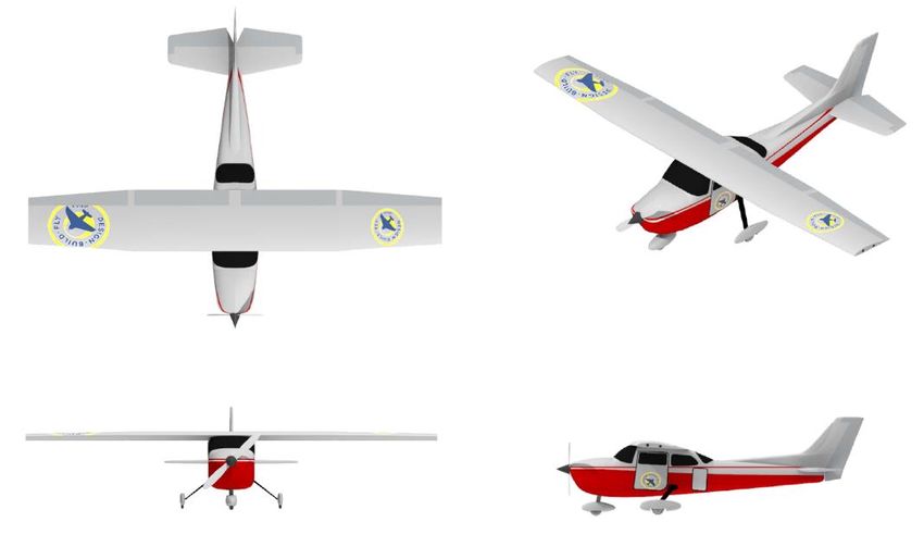
General Information
Team Requirements:
All team members (except for a non-student pilot) must be full time students at an accredited University or
College and student members of the AIAA. At least 1/3 of the team members must consist of freshman,
sophomores or juniors (below senior year, for non-four year programs). The pilot must be an AMA (Academy
of Model Aeronautics) member. Teams may use a non-university member for the pilot if desired. We will
provide qualified pilots at the contest on an as-available basis to assist teams who are unable to have their
pilot attend.
There is no set requirement for the number of students that must attend the fly-off. It is preferred, but not
required, for the team advisor or responsible faculty member to attend.
Team members may be updated/changed at any time during the contest but must always comply with the 1/3
rule. Following the initial team postings at the contest beginning we will make a “One Time” update to the
team member lists posted on the website. We will notify teams when the website update change information
may be sent, normally in February. Teams wishing a team member list update at that time must submit an
updated copy of the contest entry form with all fields fully filled (but only the team member information may
be changed).
Each educational institution may submit one (1) team entry.
The team members may be changed during the contest period, so schools may use an internal selection
process to determine their final design and team members prior to the written report submission and fly-off.
For schools with multiple campuses in different cities each campus will be considered as a separate entity.
Two or more schools may combine to submit a single entry.
Schools which already have an entry may not have additional students from their school participate as
members of a team from a different (shadow) school.

Sponsorship:
Teams may solicit and accept sponsorship in the form of funds or materials and components from commercial
organizations. All design, analysis, and fabrication of the contest entry is the sole responsibility of the student
team members.

Communications:
The contest administration will maintain a website containing the latest information regarding the contest
schedules, rules, and participating teams. The contest web site is https://www.aiaa.org/dbf
Questions regarding the contest, schedules, or rules interpretation may be sent to the contest administrator
by email at: director@aiaadbf.org
Please note that rules interpretation questions will not be answered by e-mail until after the entry date
(when all participant e-mail addresses are known), so that all teams will have equal access to all rules
information. Official questions with answers received following the entry submission date will be posted on
the website Q&A and delivered by email to all teams.

                                                         2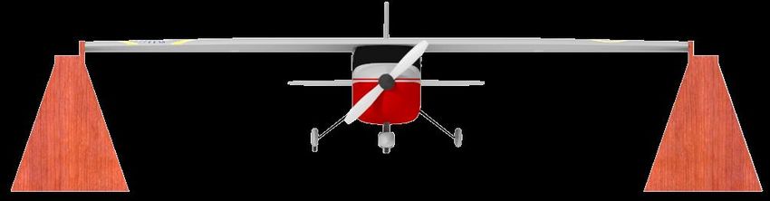
The DBF Organizing Committee will utilize social media as an additional means of communicating with the
teams during the contest weekend only. This will NOT be a means of communicating rules, FAQ's, Q&A,
protests, etc., but only used in case of emergencies, weather delays or contest weekend schedule updates.
Additional information will be included in the contest information sheet to be sent out to the registered teams
prior to the fly-off.

Flight Line and Order:
A flight order list will be generated and emailed to the teams on the Wednesday prior to the fly-off
weekend. Teams will always rotate in this order. The flight order will be repeated continuously.
The flight order list will carry over from Thursday to Friday, Friday to Saturday and Saturday to Sunday at
whatever spot in the rotation it leaves off.
Each team’s position in the flight order will be determined from their written report score, the highest report
score goes first.
Report scores will be available following the pilot briefing at the start of the contest (they will not be included
with the rotation sequence e-mail).
There will be staging box positions near the flight line.
If you are not ready to enter a staging box when your rotation number comes up, you will miss (forfeit) your
opportunity for that rotation.
Note: It is each team's responsibility to monitor the notifications from the scoring table in order to respond
if ready. A contest official will be available to help teams enter the staging box.
If you choose to leave the staging box for any reason, you may not attempt a flight until your turn comes up
again in the rotation order.

Flight Course:
The orientation (direction) of the flight course will be adjusted based on the prevailing winds as determined by
the Flight Line Judge. The flight course will be positioned to maintain the greatest possible safety to personnel
and facilities. The nominal flight course is shown in the Figure below.

                                                            3
Protest Procedure:
Submitting a protest is a serious matter and will be treated as such. Teams may submit a protest to the Contest
Administration at any time during the competition. Protests MAY NOT be submitted after the conclusion of
the competition. Protests must be submitted in writing and signed by the team advisor; designees are not
allowed for protest submissions. If the team advisor is not present, he or she may send by electronic method a
signed protest to the team for them to present. Electronically submitted protests must be on hard copy
(printed by the team) and have the advisor’s signature. A phone number where the advisor may be contacted
must be provided. Protests may be posted for review at the decision of the administration.
Protests and penalties (up to disqualification from the contest for deliberate attempts to misinform officials,
violate the contest rules, or safety infractions) will be decided by the Contest Administration. Protests
submitted but not upheld by the judges may be given a penalty of the loss of one flight score to the team
submitting the protest. The decision of the Contest Administration is final.

                                                        4
Schedule
Entries:
The entry period OPENS 15 October at 8AM (0800) US Eastern Time. No entries will be accepted before that
time. A completed entry must be RECEIVED by 5 PM (1700) US Eastern Time on 31 October. Entries will be
collected through the AIAA Online Submission System.
Proposals and Team Rosters must be submitted as part of the entry process. Proposals and Team Rosters will
not be accepted outside of the online submission system.
Be sure to include ALL required information requested by the online submission. Once submitted, corrections
to the entry, including any corrections or updates to the Proposal, will not be accepted.
If AIAA membership has been applied for, but a member number has not been issued, use "pending" for the
member number in the Team Roster form. The data must then be updated and resubmitted. Team rosters
may be updated and resubmitted during the Design Report phase of the competition.
Incomplete entries will not be accepted.
It is the team's responsibility to make sure the e-mail contact addresses they supply remain active during the
entire period from entry to the close of the competition as e-mail will be the primary means to provide
information and updates. Do not use an internal team correspondence e-mail list server as your point of
contact e-mail address.
An entry is not complete until the “Save and Finalize” function is selected in the online submission system and
confirmed.
Proposal:
Teams are required to submit the proposal with the entry via the online submission system.
The proposals will be scored as defined in the proposal requirements section. The top 110 proposals plus ties
will be invited to submit design reports and potentially become eligible for the fly-off. Teams will be notified no
later than 18 November whether their proposal has been accepted.
Proposals submitted by email will not be accepted.
Proposals will be judged “as received”. No corrections/additions/changes will be allowed by the organizers so
check your proposals carefully before submitting them. Once a Proposal is submitted, no changes are allowed.
Submission of Proposals is electronic only (no hard copy required). The details for the electronic format and
submission are at the end of the proposal section in this rules document.
5Design Report:
Design Reports will be submitted using the online system.
The design report submission period OPENS 1 February at 8AM (0800) US Eastern Time. The design report
must be submitted by 5 pm (1700) US Eastern Time on 24 February 2023.
The reports will be scored as defined in the design report requirements section. Reports submitted by email
will not be accepted.
Reports will be judged “as received”. No corrections/additions/changes will be allowed by the organizers so
check your reports carefully before submitting them. Once a Report is submitted, no changes are allowed.
Submission of Reports is electronic only (no hard copy required). The details for the electronic format and
submission, including a requirement for an additional, separate 3-view drawing, are at the end of the report
section in this rules document.
Contest Fly-off:
The contest fly-off is tentatively scheduled for 13 - 16 April 2023 and is anticipated to run from 12PM (1200) to
6PM (1800) on Thursday, 7AM (0700) to 6PM (1800) on Friday, 7AM (0700) to 6PM (1800) on Saturday and
7AM (0700) to 5PM (1700) on Sunday. Awards will be presented at 5:30PM (1730) on Sunday. All teams
should plan their travel so that they may stay for the awards presentations on Sunday. A final contest
schedule will be e-mailed to the teams prior to the contest date.
Tech inspections will begin on Thursday afternoon and will continue as required on Friday, Saturday and
Sunday.
To help streamline the contest flow and maximize opportunities for each team to get their flights in, the Tech
inspections will be conducted in the same order as the flight rotation (which is based on report scores) so that
the first teams inspected will be the first teams in the flight queue. Teams may use the sequence to help
estimate when they need to arrive at the contest site to make sure they do not miss their slot in the first tech
inspection rotation.
PLEASE NOTE: All schedule deadlines are strictly enforced
All deadlines are based on when an entry or submission is Received (Save and Finalize) by Contest officials via
the online submission system.
Late entries and proposals will NOT be accepted.
Late report submissions will NOT be accepted.
There is no allowance for computer, internet, or power outages by the submitter, or any other type of error
beyond the control of the DBF Organizing Committee.
Teams which do not submit the required electronic report and additional 3-view drawing will NOT be allowed
to fly.
It is the team’s responsibility to assure that all deadlines are known, understood, and met.
6Fly-off Site
Host for the competition will be Raytheon Technologies. The fly-off is planned to be held at Tucson
International Modelplex Park Association (TIMPA) in Tucson, AZ. Details on the contest site and schedule will
be sent to registered teams 2 - 3 weeks prior to the flyoff. You can check on historical weather conditions at
www.weatherbase.com or www.weatherunderground.com.
Teams are advised to check with their airlines on what materials they will be allowed to bring both to and from
the contest site. Hazmat items like paints, thinners and glues may need to be purchased locally and PROPERLY
disposed of following the contest. **NOTE: It is the team’s responsibility to ensure that their aircraft arrives at
the fly-off location. Neither AIAA nor the corporate sponsors will assist in getting your aircraft or materials to
the fly-off location. Teams may hand carry their aircraft, use a shipping company to have it delivered to their
hotel, or use any other means of transportation that they feel is appropriate. But each team must coordinate
all aspects of getting the aircraft to the fly-off.
International Teams: Special information for non-US teams can be found here.
7Mission and Vehicle Design
Mission Task Matrix:
Electronic Warfare
The objective for this year is to design, build, and test an aircraft to execute electronic warfare (EW) missions.
Flight missions will include staging of the aircraft, surveillance, and jamming.
General:
• All components of the airplane, payloads and batteries must fit inside an airline checked baggage
compliant shipping box with the following characteristics:
• A maximum length + width + height of 62.00 inches (outside dimensions).
• A maximum weight of 50.00 pounds including the shipping box.
• Each team must provide two sets of one left and one right wing section. All wing sections must fit
inside the shipping box. The left and right wing sections together must make up at least 80% of the
total wing span. The wings shall be permanently marked with “L1”, “L2”, “R1” and “R2”.
• Payloads:
• Mission 1 – no payload.
• Mission 2 – Electronic Package.
• Mission 3 – Jamming Antenna.
• Electronic Packages will be provided by each team and must have the following physical
characteristics:
▪ Size: 3.00 x 3.00 x 6.00 inches minimum dimensions
▪ Weight: The weight may be varied to achieve mission objectives with a max weight declared
at tech inspection. The max weight will be measured and recorded in pounds at tech
inspection. The minimum weight of the Electronics Package must be equal to or greater than
30% of the gross vehicle weight flown during that mission.
• The Electronics Package must be carried internally to the aircraft. No part of the Electronics
Package can be part of or extrude outside of the airplane external surfaces or features.
• Jamming Antennas will be provided by each team. Teams are allowed up to three different
length antennas to optimize their mission score. All Jamming Antennas must be carried in the
shipping box for all missions. The length of the antennas will be verified and documented at tech
inspection. The Jamming Antenna will have the following characteristics:
▪ Material: Unmodified ½ inch Schedule 40 PVC pipe in accordance with ASTM-D1785 or
equivalent (the section of pipe that identifies it as schedule 40 must be visible at tech
inspection).
8▪ If a cap is used to close the open end of the pipe, it must be removable for inspection at all
times.
▪ No internal stiffeners may be added to antenna.
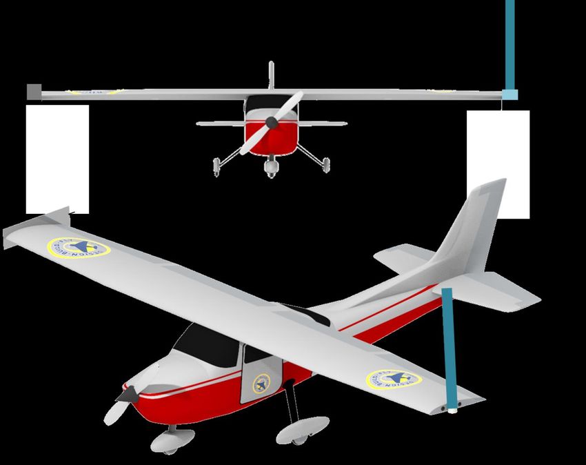
• The Jamming Antenna will be securely attached to the wing tip with two fasteners using an
adapter of the team’s design; the Jamming Antenna must be capable of attaching to both wing
tips without modification.
• The antenna must project vertically above the wing. No portion of the antenna may project
below the lower surface of the wing.
Figure 1: Jamming Antenna Attachment and Orientation
• The length of the antennas will be measured from the point the antennas exit the adapter.
• Teams are allowed to attach a counter-weight to the opposite wing tip with Jamming Antenna
installed; the counter-weight will be part of the wing tip test IF that is the heaviest payload for
tech inspection.
• The Jamming Antenna interface on the wing tips must also be used to attach a ground test fixture
using only the two fasteners for attaching the antenna adapter; teams will provide their own
9ground test fixture; the ground test fixture must be strong enough to support the aircraft during
the ground mission and prevent grounding (must not touch anything but the fixture interface) of
the airplane during the ground test; the ground test fixture DOES NOT need to be included in the
shipping box.
Figure 2: Ground Test Fixture
Mission Sequence:
• Aircraft must be capable of performing all required missions.
• During Tech Inspection, the aircraft must pass the wing tip load test in the flight condition with
the maximum weight payload declared using both sets of wing sections.
• The maximum load demonstrated will be recorded and cannot be increased after completing
Tech Inspection.
• The Flight Missions must be flown in order.
• A new mission cannot be flown until the team has obtained a successful score for the preceding
mission.
• The ground mission can be attempted at any time.
• The aircraft must be flown in the same configuration for all three missions excluding the mission 3
payload and optional counter-weight.
• After successfully completing all three flight missions, teams will be allowed one additional attempt for
both Mission 2 and Mission 3 to improve their score.
• After successfully completing the ground mission, teams will be allowed one additional attempt to
improve their score.
• The aircraft will be brought to the staging box in the shipping box with all aircraft components and
payloads.
• If you forget something you must leave the staging box and forfeit the flight attempt.
• Only the assembly crew member, pilot, and observer may go to and enter the staging box or Ground
Mission area.
10• The assembly crew member is the only person who can touch the airplane while inside the staging
box while preparing the aircraft for flight.
• Prior to entering the staging box, the shipping box will be weighed to verify it does not exceed 50
pounds; if the shipping box exceeds 50 pounds, the team will forfeit that flight attempt.
• The aircraft assembly and payload installation must be completed in less than 5 minutes.
• There is no work allowed on the aircraft after the 5-minute assembly and checkout time including
connection of batteries, receivers, etc. The aircraft must be ready to fly prior to being called to the
flight line, less the installation of the arming fuse.
• After loading and checkout is complete, the assembly crew member may be swapped for a different
flight line crew member, if desired.
• Aircraft will use ground rolling takeoff and landing.
• The aircraft must take-off within 60 feet of the start/finish line. All ground contact points of the
aircraft MUST be forward of the start/finish line.
• The initial upwind turn on the first lap of each mission will occur after passing the turn judge (signaled
by raising a flag).
• The aircraft must always remain in unaided visual control distance of the pilot. The Flight Line Judge
may require turns to be made to remain in a safe visual control range at his discretion.
• Aircraft must complete a successful landing at the end of each mission for the mission to receive a
score.
• A successful landing is outlined in the general mission specifications section below.
Flight Missions:
Mission 1: Staging Flight
• There is no payload for Mission 1.
• The aircraft must enter the staging box inside the closed shipping box.
• Upon entering the staging box, the teams will flip a coin twice to determine which wing set
components will be used for that mission.
Coin Flip Wing Selection
Heads “L1” or “R1”
Tails “L2” or “R2”
• Takeoff field length is 60 feet.
• Teams must complete 3 laps within the flight window.
11• There will be a 5-minute flight window for this mission.
• Time starts when the aircraft throttle is advanced for the first take-off (or attempt).
• A lap is complete when the aircraft passes over the start/finish line in the air (the landing is not part of
the 5-minute time window).
• Must complete a successful landing to get a score.
Scoring:
M1 = 1.0 for successful mission.
Mission 2: Surveillance Flight
• The payload for Mission 2 is the Electronics Package.
• The aircraft must enter the staging box inside the closed shipping box.
• Upon entering the staging box, the teams will flip a coin twice to determine which wing set
components will be used for that mission.
Coin Flip Wing Selection
Heads “L1” or “R1”
Tails “L2” or “R2”
• Takeoff field length is 60 feet.
• There will be a 10-minute window for this mission.
• The score will be a function of the Electronics Package weight * number of laps flown.
• Time starts when the aircraft throttle is advanced for the first take-off (or attempt).
• A lap is complete when the aircraft passes over the start/finish line in the air (the landing is not part of
the 10-minute time window).
• Must complete a successful landing to get a score.
• Post flight, the aircraft and Electronics Package will be weighed to verify the payload weight is equal to
or greater than 30% of the gross vehicle weight of the aircraft as flown and to record the payload
weight.
Scoring:
M2 = 1 + [N_(payload weight * # laps flown) / Max_(payload weight * # laps flown] , where Max_(payload
weight * # laps flown) is the highest payload weight * # laps flown score of all teams.
Mission 3: Jamming Flight
• The payload for Mission 3 is the Jamming Antenna.
12• The aircraft must enter the staging box inside the closed shipping box.
• Upon entering the staging box, the teams will flip a coin twice to determine which wing set
components will be used for that mission.
Coin Flip Wing Selection
Heads “L1” or “R1”
Tails “L2” or “R2”
• The Jamming Antenna must be mounted on the side of the airplane opposite of the flight safety line in
the direction of takeoff, as directed by the flight line judge.
• The length of the Jamming Antenna used will be recorded on the score sheet.
• Takeoff field length is 60 feet.
• There will be a 5-minute window for this mission.
• Teams will be timed for 3 laps.
• The score will be a function of the Jamming Antenna length / mission time.
• Time starts when the aircraft throttle is advanced for the first take-off (or attempt).
• A lap is complete when the aircraft passes over the start/finish line in the air (the landing is not part of
the 5-minute time window).
• Time stops when the aircraft passes over the start/finish line in the air at the end of the third lap.
• Must complete a successful landing to get a score.
Scoring:
M3 = 2 + [N_(antenna length / mission time) / Max_(antenna length / mission time)] , where Max_(antenna
length / mission time) is the highest antenna length / mission time of all teams.
Ground Mission: Structural Margin Demonstration
• The Ground Mission is a demonstration of aircraft structural margin.
• The teams will enter the ground mission with all aircraft components and payloads inside shipping box.
• Upon entering the staging box, the teams will flip a coin twice to determine which wing set
components will be used for that mission.
Coin Flip Wing Selection
Heads “L1” or “R1”
Tails “L2” or “R2”
• The assembly crew member and a pilot may participate in the Ground Mission; only the assembly crew
member can touch the aircraft and payloads.
13• There will be a 10-minute window for this mission, which includes assembly of the aircraft and
installation of the payload, installing the ground test fixture and applying test weights.
• The assembly crew member will assemble the airplane and install the heaviest payload configuration
as declared in tech inspection. This weight will be verified by Ground Mission judge before beginning
the test.
• The pilot will verify all flight controls are working properly.
• The assembly crew member will install the structural test fixture onto the wing tips.
• The assembly crew member will apply test weights to the center of the aircraft fuselage until max
weight is called or time expires. Weights must be applied inboard of the wing section attachment
joint. If an aid or adapter is used to apply the weights, its weight will be part of the test weight.
• There will be a 30 second hold with the final test weight applied.
• While still under load on the fixture, the pilot will verify flight controls are still functioning.
• The assembly crew members will remove the test weights and the amount of weight applied will be
measured and recorded on the score sheet.
• If structural failure or deformation occurs or the flight controls are not functioning, the test is a failure.
• The mission score is a function of total test weight / max aircraft weight. Total test weight is the test
weight applied plus the max aircraft weight.
Scoring:
GM = [[N_(total test weight / max aircraft weight) / Max_(total test weight / max aircraft weight)] , where
Max_total test weight / max aircraft weight is the maximum total test weight / max aircraft weight for all
teams.
Aircraft Requirements:
General
• The aircraft may be of any configuration except rotary wing or lighter-than-air.
• No structure/components may be dropped from the aircraft during flight.
• No form of externally assisted take-off is allowed. All energy for take-off must come from the on-
board propulsion battery pack(s).
• Must be propeller driven and electric powered with an unmodified over-the-counter model electric
motor. May use multiple motors and/or propellers. May be direct drive or with gear or belt reduction.
• Motors must be any commercial brush or brushless electric motor.
• For safety, each aircraft will use a commercially produced propeller/blades. The propeller can have
folding blades. Teams may modify the propeller diameter by clipping the tip and may paint the blades
14to balance the propeller. No other modifications to the propeller are allowed. Commercial ducted fan
units are allowed.
• You can change the propeller diameter/pitch for each flight attempt.
• Aircraft and pilot must be Academy of Model Aeronautics (AMA) legal. This means that the aircraft
TOGW (take-off gross weight with payload) must be less than 55-lb, and the pilot must be a member of
the AMA. All pilots must sign in and verify AMA membership.
• Since this is an AMA sanctioned event, the team must submit proof that the exact aircraft being
presented at Tech Inspection has been flown prior to the contest date to the technical inspection
team. Proof of flight is a video showing controlled straight and level flight. There are no exceptions
to this requirement.
• Qualified pilots will be available at the contest on an as-available basis to assist teams who are unable
to have their pilot attend.
• The aircraft must remain substantially the same as documented in the report (for example you cannot
change a flying wing design to a conventional tail design). You may make small modifications to the
design to improve flight performance after the report submission (one example would be changing a
control surface size). The three-view drawing supplied in PDF form as described below in the
electronic report section will be used to verify the flight article during tech inspection.
• The aircraft must have an externally accessible switch to turn on the radio control system. It cannot
be internal or under a panel or hatch.
Batteries
• There can be a maximum of one battery pack connected to a propulsion system. A propulsion
system consists of one battery, one externally accessible arming fuse, one or more electronic speed
controllers (ESC), and one or more motors.
• If more than one battery pack is implemented for a single purpose such as propulsion, the following
rules apply:
• All commercial battery packs must be identical (same manufacturer, part number, size, voltage,
power, rating, etc).
• Each battery pack must be independently connected to its own propulsion system. Batteries
cannot be connected in series or parallel.
• Each battery/propulsion system is required to have its own Arming Fuse.
• Teams may choose between NiCad/NiMH OR Lithium Polymer (LiPo) batteries with the following
provisions:
• Teams may only use one battery type for propulsion.
• Once a team completes tech inspection with a specific battery type, the team must use that
battery type for the remainder of the competition.
• Teams may use either battery type for Rx/Servo and Transmitter power regardless of the
propulsion battery type.
15• Propulsion power total stored energy cannot exceed 100 Watt-hours.
• NiCad/NiMH Battery requirements:
• Must be commercially procured battery pack assemblies or individual battery cells.
• Battery packs must be properly labeled indicating cell chemistry.
• Individual battery cells must have the manufacturer’s label readable/documented (i.e. clear
shrink wrap preferred).
• All battery disconnects must be "fully insulated" style connectors.
• LiPo Battery requirements:
• LiPo battery packs must be un-altered and commercially procured.
• Individual battery packs cannot exceed the FAA limits for hand carry on commercial air flights of
100 Watt-hours (rated capacity x rated voltage) per battery pack and as further defined in:
https://www.faa.gov/hazmat/packsafe/resources/media/Airline_passengers_and_batteries.pdf
• The maximum rating of the Arming Fuse for LiPo Propulsion batteries must not exceed the
maximum continuous discharge current rating of the LiPo battery pack (battery capacity X C-
rating) up to 100 Amps.
• LiPo batteries must be stored and charged in a commercially available, unaltered LiPo
charging sack – the only time they can be out of the sack is for tech inspection or while in
the airplane.
• The Manufacturer's Label stating the Battery Capacity (mAh), Voltage (V), and C-Rating
must be clearly visible.
NOTE: It is the responsibility of each team to assure compliance with all laws and regulations for
shipping or hand-carrying LiPo batteries.
• Batteries may not be changed or charged during any mission attempt.
• There is no limit to total battery weight (only capacity).
16Technical Inspection:
All vehicles will undergo a technical inspection by a designated contest tech inspector prior to being allowed to
make any competition flight or ground mission. All decisions of the Tech inspector are final.
To speed up the tech inspection process, each team MUST present a signed Pre-Tech and First-Flight
Certification when called to begin their on-site tech inspection. Teams may not begin the on-site tech
inspection without a completed certification. The Pre-Tech and First-Flight Certification sheet is available on
the contest website.
The Pre-Tech must be conducted by, and signed off by, a non-team member RC pilot or the team faculty
advisor. The Pre-Tech will cover the same safety of flight requirements as the on-site tech inspection and will
assist teams in making sure they are ready and able to pass the on-site tech inspection the first time. An
expanded First-Flight requirement, which also must be signed off by a non-team member RC pilot or the team
faculty advisor, requires demonstration of a complete flight including take-off, flying a minimum flight pattern,
and landing in a pre-designated location without damage to the aircraft. The non-team member RC pilot who
signs the inspection and flight certifications may be the same as a team's non-student contest pilot.
Aircraft Staging:
• The Aircraft will enter Tech Inspection in the flight configuration with no payload items installed
• Team members will declare:
• Maximum Mission 2 EW Payload Weight.
• Number and length of Mission 3 payload (3 max).
• All batteries and battery packs must be inspected during Tech Inspection. Teams should bring all
possible batteries for use over the full duration of the competition to Tech Inspection.
NOTE: Teams will be allowed to have additional batteries or battery packs inspected after passing Tech
Inspection due to damage, real time power change requirements, etc. However, teams must follow the Tech
Inspection queue or wait until Tech Inspection is open for all for additional battery inspections. Any team that
uses batteries that have not passed a Tech Inspection will lose that flight attempt and cannot attempt any
further flights until the batteries have passed inspection.
Safety inspections will include the following as a minimum:
Physical inspection of vehicle to ensure structural integrity:
1. Verify all components adequately secured to the vehicle. Verify all fasteners are tight and have either
safety wire, thread locker (LoctiteTM ), or nylock nuts. Clevises on flight controls must have an
appropriate tech device to prevent their disengaging in flight.
2. Verify propeller structural and attachment integrity.
3. Visual inspection of all electronic wiring to assure adequate wire gauges and connectors in use.
4. Radio range check with motor off and motor on.
175. Verify all controls move in the proper sense.
6. Check the general integrity of the payload system.
Structural verification:
All aircraft will be lifted with one lift point at each wing tip to verify adequate wing strength (this is
"roughly" equivalent to a 2.5g load case) and to check for vehicle cg location. Teams must mark the
expected empty and loaded cg locations on the exterior of the aircraft. Special provisions will be made at
the time of the contest for aircraft whose cg does not fall within the wing tip chord. This test will be made
with the aircraft filled to its maximum payload and battery (combination) capacity.
Radio fail-safe check:
All aircraft radios must have a fail-safe mode that is automatically selected during loss of transmit signal. The
fail-safe will be demonstrated on the ground by switching off the transmit radio. During fail-safe the aircraft
receiver must command:
• Throttle closed
• Full up elevator
• Full right rudder
• Full right aileron
• Full Flaps down
For aircraft not equipped with a particular control, then the tech inspector must be satisfied that the intended
function of the fail-safe system will be carried out.
The radio Fail Safe provisions will be strictly enforced.
All aircraft must have a mechanical motor arming fuse separate from the onboard radio Rx switch. This MUST
be the contest specified "blade" style fuse. This device must be located so it is accessible by a crewmember
standing ahead of the propeller(s) for pusher aircraft, and standing behind the propeller(s) for tractor aircraft
(i.e. the crew member must not reach across the propeller plane to access the fuse). The "Safety Arming
Device" will be in "Safe" mode for all payload changes. The aircraft Rx should always be powered on and the
throttle verified to be "closed" before activating the motor arming switch. Fuses MUST be mounted on the
outside the aircraft (they can not be behind an access panel or door) and MUST act as the "safing" device.
Note: The aircraft must be “safed” (arming fuse removed) any time the aircraft is being manually moved, or
while loading/unloading payloads during the mission. The arming fuse must be removed anytime the aircraft is
in the hanger area.
The maximum current rating for the Arming Fuse is 100 amps.
• If using LiPo batteries, the maximum current rating for the fuse is the maximum continuous discharge
current rating of the LiPo battery pack (battery capacity X C-rating) up to 100 amps.
18General Mission Specifications and Notes:
• The aircraft propulsion system(s) must be "safed" (fuse removed) during any time when crew
members are preparing/handling the aircraft.
• Maximum flight support crew is: pilot, observer, and ground crew.
• Observer and all ground crew must be students. Only the pilot may be a non-student.
• The upwind turn will be made after passing the upwind marker. The downwind turn will be made after
passing the downwind marker. Upwind and downwind markers will be 500 ft from the starting line.
Aircraft must be "straight and level" when passing the turn marker before initiating a turn.
• "Successful" Landing - Aircraft must land on the paved portion of the runway. Aircraft may "run-off"
the runway during roll-out. Aircraft may not “bounce” off the runway.
• Aircraft obtaining “significant” damage during landing will not receive a score for that flight.
Determination of “significant” is solely at the discretion of the Flight Line Judge.
• Flight altitude must be sufficient for safe terrain clearance and low enough to maintain good visual
contact with the aircraft. Decisions on safe flight altitude will be at the discretion of the Flight Line
Judge and all rulings will be final.
• All instructions from the Flight Line Judge must be followed IMMEDIATELY. Failure to do so may
result in a loss of mission attempt or in the case of multiple or serious infractions, loss of future
flight attempts.
• Additional information is included in the FAQ (Frequently Asked Questions).
19Reports
All material contained within all proposals and design reports must be original work of the teams or
appropriately cited in the bibliography section of the report or in the footnotes of the proposal. All proposals
and reports will be reviewed using standard AIAA tools. Any material that is found to be uncited and non-
original work will be subject to a penalty as determined by the DBF Organizing Committee. Based on the
severity, penalties can include points deducted from the proposal or report score up to a 100% reduction or
full disqualification for the competition year.
Proposal:
Each team will submit a proposal as outlined below that will be judged.
Examples of top scoring proposals from prior contest years are posted on the contest website. Note that the
formatting and content may have changed from one year to the next. Prior year proposals may not reflect or
meet the rules listed for the current year.
Note: Proposals must strictly adhere to the following requirements. Failure to meet requirements
will result in penalties that range from score reduction to elimination from the contest.
Formatting Requirements:
• Proposals must be in PDF format. Proposals that are not in PDF format will not be accepted.
• Proposals must be one and one-half line spacing with a 10-pt Arial font recommended. Text, tables,
and figures should be clear and readable for the judges. The proposals will be assessed for format and
readability at the judges’ discretion.
• Proposals must have the University name on the first page.
• Absolute maximum page count for the proposal is 5 pages, the PDF reader "pages" value will be used
as the official page count.
• Proposals exceeding the maximum page count will not be accepted.
• Proposal PDF must be formatted as 8.5” x 11" pages.
Submission Requirements:
Each team must provide an electronic copy of their proposal as outlined below to the online Submission site.
• Electronic proposal must be named: “2023DBF_[university name]_PROPOSAL.pdf" .
• University name should not be an acronym.
• Universities with multiple campuses should specify which campus in the university name.
Proposals that do not meet the file naming convention above will incur a 10-point penalty.
• Electronic proposal must be a single file with all figures/drawings included in the proper sequence in
PDF format.
• Electronic proposals should have all figures compressed to print resolution to minimize file size.
20• Electronic proposals must be less than 20 MB in size.
Proposals exceeding the file size will incur a 10-point penalty.
Summary of Proposal Non-Compliance Penalties
Requirement Penalty
Must be in PDF format Rejection (Not Accepted)
Maximum page count of 5 pages Rejection (Not Accepted)
File naming convention (2023DBF_[university name]_PROPOSAL) 10 points
File size (• Preliminary design / sizing results; concept sketch, if available (does not have to be representative of
the final design).
• Sensitivity Study of Design Parameters.
Manufacturing Plan (15 points):
• Preliminary manufacturing flow.
• Describe critical processes or technologies required.
Test Planning (15 points):
• Component and ground test plan.
• Flight test plan.
Design report:
Each team will submit a design report as outlined below that will be judged.
Examples of winning team design reports from prior contest years are posted on the contest website. Note
that the formatting and content has changed from one year to the next. Prior year reports may not reflect or
meet the rules listed for the current year.
Note: Reports must strictly adhere to the following requirements. Failure to meet requirements
will result in penalties that range from score reduction to elimination from the contest.
Formatting Requirements:
• Reports must be in PDF format.
Reports that are not in PDF format will not be accepted.
• Reports must be one and one-half line spacing with a 10-pt Arial font recommended. Text, tables and
figures should be clear and readable for the judges. The reports will be assessed for format and
readability at the judges’ discretion.
• Reports must have the University name on the cover page.
• Absolute maximum page count for the report is 60 pages, the PDF reader "pages" value will be used as
the official page count.
Reports exceeding the maximum page count will incur a 10-point penalty for each additional page.
• Report PDF must be formatted as 8.5” x 11" pages.
• May use 11” x 17" pages for the drawing package.
• An additional stand-alone 3-view drawing must be submitted along with the report file. See
description below in the electronic submission section.
22Submission Requirements:
Each team must provide an electronic copy of their design report as outlined below to the online Submission
site.
• Electronic report files must be named: “2023DBF_[university name]_DESIGN_REPORT.pdf”.
Reports that do not meet the file naming convention above will incur a 10-point penalty.
• Electronic report must be a single file with all figures/drawings included in the proper report sequence
in PDF format.
• Electronic reports should have all figures compressed to print resolution to minimize file size.
• Electronic reports must be less than 20 MB in size.
Reports exceeding the file size will incur a 10-point penalty.
Stand Alone 3-view drawing requirements:
• In addition to the drawings included within the design report, an additional, separate file with a one
page 3-view drawing formatted to fit 8.5" x 11" paper must be submitted with the report for
confirmation of the basic configuration. Note that this page DOES NOT count toward the report total
page count.
• The 3-view drawing file must be named: “2023DBF_[university name]_THREE_VIEW.pdf”.
• University name should not be an acronym.
• Universities with multiple campuses should specify which campus in the university name.
• The university and team names shall be clearly shown on the drawing.
• The 3-view drawing file is limited to 2 MB in size.
3-view drawings that do not meet the file naming convention above or the format below will incur a 10-
point penalty
23Figure 3: Required 3-View Drawing Format
Summary of Report Non-Compliance Penalties
Requirement Penalty
Must be in PDF format Rejection (Not Accepted)
Maximum page count of 60 pages 10 points per additional page
Report File naming convention (2023DBF_[university 10 points
name]_DESIGN_REPORT)
Report file size (Conceptual Design (15 Points):
• Describes mission requirements (problem statement).
• Translate mission requirements into sub system design requirements.
• Present a scoring sensitivity analysis.
• Review solution concepts/configurations considered.
• Describe concept weighting and selection process and results.
Preliminary Design (20 Points):
• Describe design/analysis methodology.
• Document design/sizing trades.
• Describe/document methodology for prediction of aircraft performance
(include capabilities and uncertainties).
• Provide estimates of the aircraft lift, drag and stability characteristics and method of prediction.
• Provide estimates of the aircraft mission performance.
Detail Design (15 Points + 15 Points for Drawing Package):
• Document dimensional parameters of final design.
• Document structural characteristics/capabilities of final design.
• Document systems and sub-systems selection/integration/architecture.
• Document Weight and Balance for final design.
• Must include Weight & Balance table empty and with each possible payload/configuration.
• Document flight performance parameters for final design.
• Document mission performance for final design.
• Drawing package:
• 3-View drawing with dimensions of all configurations.
• Structural arrangement drawing.
• Systems layout/location drawing.
• Payload(s) accommodation drawing(s).
Manufacturing Plan (5 Points):
• Document the process selected for major component manufacture.
• Manufacturing processes investigated and selection process and results.
• Manufacturing milestones chart: plan and actual.
25Testing Plan (5 points):
• Describe all major ground and flight tests performed.
• Objectives and schedule for each.
• Data to be collected and how applied.
• Test and flight check lists.
Performance Results (10 Points):
• Describe the demonstrated performance of key subsystems following execution of testing plan.
• Compare test results to predictions and explain any differences and improvements made.
• Describe the demonstrated performance of your complete aircraft solution.
• Compare test results to predictions and explain any differences and improvements made.
Bibliography (5 Points):
• Must include list of all published works referenced in the text must be present in this section.
• Any material taken from a published source in all previous sections must have a numerical subscript
corresponding to the appropriate citation in this section.
• References should appear in numerical order.
• Format should match AIAA provided guidelines:
https://www.aiaa.org/publications/journals/reference-style-and-format
26Scoring
In the event that, due to time or facility limitations, it is not possible to allow all teams to have the maximum
number of flight attempts, the contest committee reserves the right to ration and/or schedule flights. The
exact determination of how to ration flights will be made on the contest day based on the number of entries,
weather, and field conditions. In the event of a tie, Report Score will take precedence over Flight Score as a
tie-breaker.
Judging:
Students must design, document, fabricate, and demonstrate the aircraft they determine to be capable of
achieving the highest score on the specified mission profile(s). Mission scores will be based on the
demonstrated mission performance obtained during the contest.
Each team must also submit a written Design Report. A maximum of 100 points will be awarded for the team
design report. The overall team score is a combination of the Design Report score and Total Mission Score.
The team with the highest overall team score will be declared the winner. Scores will be FINAL 7 working days
after the completion of the contest. This period will allow for review of the scores in a timely fashion following
the contest.
All submitted reports are the property of AIAA, Textron Aviation and Raytheon Missiles and Defense may be
published or reproduced at their discretion.
Units of Measure:
The units of measure for scoring will be based on the US English system. All times or physical measurements
will be rounded to the number of decimal places shown in Table 1. Conventional rounding will be
implemented ( round down, >= 0.5 --> round up).
Units of Measure and Number of Decimal Places
Item Unit of Measure Decimal Places
Time Seconds (s) 2 (e.g. X.XX)
Length Inches (in) 2 (e.g. X.XX)
Ounces (oz) 2 (e.g. X.XX)
Weight
Pounds (lbs) 2 (e.g. X.XX)
27Total Score:
Each team's overall score will be computed from their Design Report Score and Total Mission Score using the
following formula:
Competition Score = Design Report Score * Total Mission Score + P
P = Participation Score as follows:
P Participation
1 Attending the Fly-off
2 Completing Tech Inspection
3 Attempting a Flight Mission
The Total Mission Score will be computed from the individual Flight Mission and Ground Mission Scores using
the following formula:
Total Mission Score = M1 + M2 + M3 + GM
28You can also read