Simulation on Human Body Injury Locations during a Fall due to Slip
←
→
Page content transcription
If your browser does not render page correctly, please read the page content below
Simulation on Human Body Injury Locations
                       during a Fall due to Slip
                                     Ha Van Vo 1 and R, Radharamanan 2

Abstract – Most of the engineering projects at Mercer University School of Engineering require some level of
simulations before the construction of prototypes. This paper presents one such study where students carried out
simulations on human body injury locations during a fall due to slip. The objective of this study is to analyze the
varying forces in the fall injuries that depend on the location of the center of gravity of the body. Force versus time
dependent simulations were carried out using Lifemod software for thoracic and lumbar vertebrae. The simulation
results showed that the highest and the lowest compressive stresses occur at the lumbar vertebrae (2,250 psi) and
thoracic vertebrae (1,750 psi) respectively. The stresses calculated were significantly lower than the ultimate stress
value of cortical bone. It can be concluded that there will be no bone fracture occurring at the vertebrae but there
will be possibly ligaments and muscles tearing.

Keywords: Injury biomechanics, falling accident, slip and fall, vertebral simulation, and ligament sprain.

                                                  INTRODUCTION
In the area of injury biomechanics, the students were taught to build a 3D Finite Element model to conduct a series
of computer simulation and finite element analysis of the human motion to predict and determine the locations, and
mechanical loads acting in a specific structure of the human body. This paper is one the example of the simulation
relating to injury mechanics. Results have shown that students have understood well and better in this area and they
did well in the final exam.

Falling is a common accident that has seen in construction works and more importantly in worker compensation
cases. People can fall while they are at work and could be involved in serious injuries and death. Center for disease
control (CDC) estimated that “one million people suffered a slip, trip or falling injury, and over 17,000 Americans
died as a result in 2004. Of the estimated 3.8 million disabling injuries each year in the work force,15 percent are
due to slips, trips, or falls, which account for 12 to 15 percent of all Workers' Compensation costs” [1]. Injury
mechanics is the field of bioengineering that describes exactly how injuries were received and what is the
biomechanics behind the injury. The basic idea that influences the severity of injury sustained is the amount of
energy absorbed by the musculoskeletal system [2]. The higher the energy absorbed the more damage the human
body will sustain and could be a leading factor in deciding between life and death. In 1996, the National Safety
Council estimated that the comprehensive cost of unintentional injuries was more than $1.2 trillion dollars [2].
Furthermore, injuries accounted for 40% of the visit to the emergency room [2]. This study analyzes the forces and
torque associated with the falls and slips and how they damage the lumbar and thoracic vertebrae.

                                                   BACKGROUND
The thoracic region is the area of the spine that is located around the chest region and it makes up the ribcage. As
shown in figure 1, the thoracic region is the second major region of the spinal column and is beneath the cervical

         1   Mercer University, 1400 Coleman Avenue, Macon, GA 31207, vo_hv@mercer.edu
         2   Mercer University, 1400 Coleman Avenue, Macon, GA 31207, radharaman_r@mercer.edu

                                     2009 ASEE Southeast Section Conference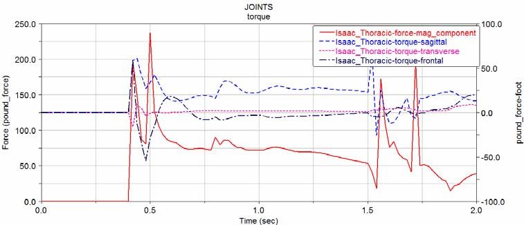
spine column. The spinal column is composed of 33 vertebrae for the human body [3]. Of the 33 vertebrae, the
thoracic region usually consists of 12 vertebrae. These regions are labeled: T1-T12.

The lumbar region is the area of the spine that is typically recognized as the lower back. As shown in figure 1, the
lumbar region is the third major region of the spinal column and supports approximately 60% of the body weight.
Therefore, they are the joints besides hip, knee and ankle that are subjected to larger load bearing application. They
are located beneath the thoracic regions of the spine and directly above the Sacrum region. Of the 33 vertebrae, the
lumbar region usually consists of five vertebrae and in a few individuals the lumbar region has six vertebrae. The
region is labeled: L1-L5

                                Figure 1: The general structure of the human spine

The spinal column is held together by a series of ligaments and tendons. The ligaments are used to connect the
various bones together while the tendons function is to connect muscle to vertebrae. Each vertebrae are stacked on
top of one another with a series of disc in between them. These gel-like discs function as cushions between the
spinal columns to help absorb the impact during compression. The discs also serve to help distribute stress and keep
the vertebrae from grinding against each other [4].

The lumbar region is the area of the spine that carries the most amount of body weight [3]. Therefore this is the
region that has to deal with the most stress and has to be able to deal with a variety of forces that affect the body.
This will explain why many people suffer lower back pains and injuries.

The various lower back injuries that can occur to a person are herniated discs, spinal stenosis, spinal fracture and
various types of arthritis. A herniated disc, spinal stenosis and spinal fracture are sometimes caused by falls
especially in the elderly.

A herniated disk happens when a disc degenerates into the spinal canal [5]. The weak spot in the disc is under a
nerve root and when the disc is herniated, the area is places pressure on the nerve causing severe pain. Spinal
Stenosis is a pain caused by a narrowing of the spinal canal [6]. This narrowing of the spinal canal causes the nerves
that travel through the lower back to become compressed leading to pain for the individual. A spinal fracture usually
occurs in individuals who have thinning bones [7]. When these thinning bones weaken over time they cause a
compression which can lead to the bones in the spinal column collapsing.

Some of these problems can lead to life long problems like paralysis.

         “Spinal cord injury (SCI) involves damage to the nerves within the spinal canal; most SCIs are
         caused by trauma to the vertebral column, thereby affecting the spinal cord's ability to send and
         receive messages from the brain to the body's systems that control sensory, motor and autonomic
         function below the level of injury” [8].

                                     2009 ASEE Southeast Section Conference
Permanently damaged nerves can lead to paralysis [8]. The nerves around the lumbar region control the signals that
are sent to the legs and hips. Damage to these nerves can lead to loss of control in the same areas. After an injury,
the nerves that can send signals to their limbs are able to repair themselves over time. However completely injured
nerves usually do not regenerate. Nerves that fail to regenerate cannot send signals to areas below the injury.

                                          MATERIALS AND METHODS
The main goal of this study was to analyze the forces that are developed at the anatomical joints at the time of
impact during a slip, trip, and fall injuries. These forces can be calculated numerically by developing a mathematical
model or by using a computational model by performing computer simulations. This study focused on using a
computational software modeling called Lifemod [9], which can be used to predict human motion when subjected
under loading conditions. In order to use the software correctly, four steps were followed to arrive at the results:
create 3D skeletal model, attach muscles and skin to the skeleton, assign materials property and boundary
conditions, and run the simulation.

The Skeletal body was created for a 170 pound person with a height of 5’5”. The units were set to foot, pound mass,
and pound force. The center of gravity (COG) is located 2 inches anterior to sacrum S2. Research suggests that for a
hybrid III dummy at 35 mph impact, the joint stiffness is approximately 1 ksi. Figure 2 shows the skeletal system
along with joints that were created to simulate the injury mechanics of a slip, trip and fall injuries. The muscles were
then added to the skeletal body and it was finally covered with skin as shown in Figure 3. The limbs were then
positioned such that the human body mimics the ideal position during the fall as shown in figure 4. The cases were
carried out for COG angles 15°, 25°, 35°, 45°, and 60°.

                    Figure 2: 3D model of the human skeletal system using for simulations.

                                     2009 ASEE Southeast Section Conference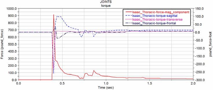
Figure 3: The complete human body with muscles Figure 4: Ideal falling position with center of
and skin attached using to create slip and fall. gravity angle (θ) shown
It was assumed that the person starts from a height of 3ft (COG height) and lands on the concrete slab with a
thickness of 1 inch. This material was selected because it is the most common material that is encountered during
construction and worker compensation related environments. The parameters for the contacts used were: Stiffness =
1E11 psi; Exponent = 3; Damping = 250 lb-s/in; Damping depth = 0.005” and Friction coefficient = 1. Time
dependent simulations were run for a total of 2.0 seconds and data were collected every 0.02 seconds. Forces were
measured around the hips, lumbar, thoracic and neck region.
RESULTS AND DISCUSSIONS
During a slip, trip and fall injuries the first joints that are severely affected are the lumbar joints. This is because it is
the first joint that comes in contact with the concrete surface and suffers the most amount of injury. The other joints
that are commonly affected are the hip, the thoracic, and the cervical spine (upper neck and lower neck).
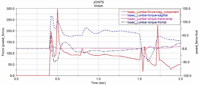
For the lumbar vertebral injuries, the following diagrams (figures 5-9) show the forces distributed over the lumbar
region simulations for the falling position angle θ at 15o, 25o, 35o, 45o, and 60o. The solid red line shows the forces
while the dashed and dotted lines represent the torques in the sagittal, transverse and frontal planes correspondingly.
Figure 5: Lumbar force distribution at 15 degree angle of slip
2009 ASEE Southeast Section Conference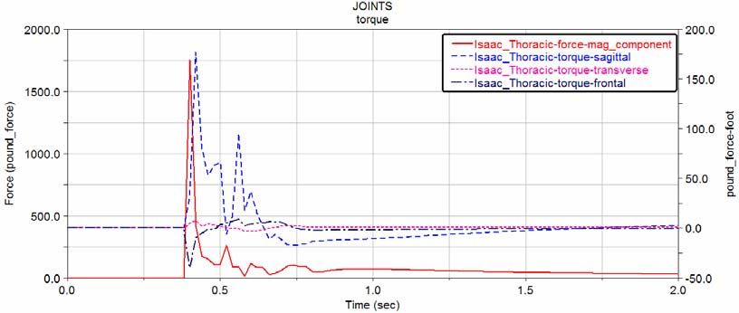
Figure 6: The lumbar force distribution at 25 degree angle of slip

 Figure 7: Lumbar force distribution at 35 degree angle of slip

Figure 8: The lumbar force distribution at 45 degree angle of slip

           2009 ASEE Southeast Section Conference
Figure 9: The lumbar force distribution at 60 degree angle of slip

For thoracic vertebral injuries, the following diagrams (figures 10-14) show the forces distributed over the thoracic
region simulations for the falling position angle θ at 15o, 25o, 35o, 45o, and 60o. The solid red line shows the forces
while the dashed and dotted lines represent the torques for the sagittal, transverse and frontal planes.

                       Figure 10: The thoracic force distribution at 15 degree angle of slip

                       Figure 11: The thoracic force distribution at 25 degree angle of slip

                                     2009 ASEE Southeast Section Conference
Figure 12: The thoracic force distribution at 35 degree angle of slip

                      Figure 13: The thoracic force distribution at 45 degree angle of slip

                      Figure 14: The thoracic force distribution at 60 degree angle of slip

Figure 15 summarizes the relationship for figures 5-14 by determining the maximum reaction force at each angle.
Lumbar vertebrae have experienced much higher compressive force of falling position angle θ at 35o, and since the
θ reaches 45o the thoracic region has experienced higher compressive load than the lumbar region due the COG
moved up to the thoracic region.

                                   2009 ASEE Southeast Section Conference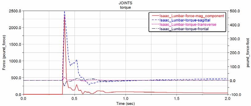
Figure 15: Reaction force and center of gravity relationship in thoracic and lumbar vertebrae

From figure 15, it can be inferred that the magnitude of the force increases rapidly until the angle is 35 degree. After
this point, the magnitude of the force decreases rapidly and would eventually reach zero. This is because the spine is
made up of four natural curves-two lordotic and two kyphotic. The cervical and lumbar curves are lordotic whereas
the thoracic and sacral curves are kyphotic .These curves along with the surrounding ligaments and muscles keep the
joints intact, prevent injury and dislocation, and distribute stress as the body undergoes a wide range of motion.
Lordosis is the curvature of the spine when a person is facing up to pray and kyphosis is the curvature of the spine
when a person is riding a horse. Figure 16 shows a free body diagram of the lumbar joint.

                                                                  FX

                                                            FM
                                            FY

                            Figure 16: A free body diagram of a lumbar vertebral joint

In figure 16, FM represents the magnitude of the reaction force that is exerted at the joints, FY represents the vertical
component of the FM, and FX represents the horizontal component of FM. Any change in the lumbar joint angle will
change the magnitude of FM, which arises primarily because of changes in normal curvature of the spine, that is
changes lordotic angle. Therefore referring back to figure0 10-14, as the angle is increased the magnitude of the
vertical component reaction force dominates in the axial direction until the angle is 45 degree. The horizontal
component of the reaction force at the point is very small or no longer exists. As the angle is increased further, the
joints are not aligned any more and the curvature changes from lordosis to kyphosis. The vertical component of the
force gradually decreases and the horizonal shear plays a major role in determining the magnitude of reaction force.
This explanation holds true for thoracic joints except the curvature of the thorax changes from kyphosis to lordosis.
Also as the angle is increased beyond 45 degree, the thoracic curve is more open to the ground and therefore more
prone to the injuries. Therefore this produces a slightly higher reaction force as compared to lumbar joint as the
angle is increased in figures 5-9.

Research suggests that the ultimate stress for a cortical bone is 180 MPa [10]. Also the surface area for lumbar joint
is approximately 10 [cm2] [11]. From figure 15, the maximum force in the lumbar joint is calculated to be 2250

                                     2009 ASEE Southeast Section Conference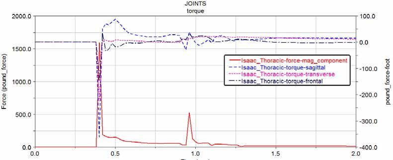
pounds. Using the equation for stress (σ = F/A), the stress in the lumbar joint is calculated to be 10.01 MPa.
Evaluating the same equation for thoracic region, the stress is calculated to be 7.78 MPa.

Both these values are signinificantly lower than the ultimate stress value of the cortical bone. However, this does not
hold true for each and every person as different people have different anatomical characteristics such as height,
weight, sex, age, bone density, and medical history. Another important factor that Lifemod model does not assume
is that at the time of the fall, different person will land in different position and will try to adjust by themselves in
order to reduce the amount of injury. Also it should be mentioned that the Lifemod software only applies on a
theoretical basis and not enough data has been accumulated that can validate the injury mechanics data. Therefore
one of the goals for future studies would involve creating a mathematical model that will attempt to validate the data
produced by Lifemod and that it will provide a better approximation for each and every individual.

                                                   CONCLUSIONS
Slip and fall injuries will be more severe when the reaction forces are maximum and this will happen when the
curvature of spine changes such that all vertebrae in that specific joint will be stacked on top of each other. In order
to reduce the expenses incurred due to fall related lower back injuries, it is recommended that fall protection and fall
prevention measures be put into place.

The purpose of fall prevention is to reduce the amount of falls that occur by doing proper planning. Many of the
prevention techniques are already the policy for protection agencies like Occupational Safety and Health
Administration (OSHA). Some of the best ways to workers from falling is to make sure that they are wearing shoes
and boots with slip resistant soles [12]. The shoes that are worn should also be in good condition. Worn out shoes or
boots can cause workers to slip and fall so supervisors should inspect their workers clothing over time.

Another good way to prevent falls is routine cleaning and maintenance [13]. Oil or water spills should be marked by
using a sign or a warning label. These spills should be cleaned up as soon as possible to reduce the risk of workers
slipping. If workers are working at night or dimly lit conditions then supervisors should make sure that work areas
are well lit. Areas that are too dark limit the field of vision of the worker which could cause them to slip. Areas that
are typically walked on should be inspected for loose items or cables. If there are cables in the way, make sure that
they are covered. Walkways should also be cleared of dust and debris daily so that workers do not lose their footing
when walking on floors. If possible flooring should be either replaced or modified. Recoating, repainting, or matting
non-slip flooring can be very helpful in reducing the number of slips that occur in the workplace.

The purpose of fall protection is to protect workers from injury in the instance that they do fall. There are numerous
ways to protect a worker when they fall [14]. Placing guardrails is a way to protect worker from falling since it can
be used to catch a falling worker. Items that can attach to the worker can also be used to protect workers from falls.
Body harness, safety belts, and lanyards can be used to attach to the worker to catch them when they fall. Also
making sure other workers and supervisors on hand can help to assist injured workers and make sure that they are
working in safe working conditions.

                                                    REFERENCES
[1]   Lehtola, Carol J., William J. Becker, and Charles M. Brown. "Preventing Injuries From Slips, Trips and Falls."
      NASD. July 2004. 23 Apr. 2008 (http://www.cdc.gov/nasd/docs/d000001-d000100/d000006/d000006.html).

[2]   Whiting, William C., and Ronald F. Zernicke. Biomechanics of Musculoskeletal Injury. 2nd ed. Human
      Kinetics, 1998.

[3]   Bellenir, K. "Lumbar Spine." Back.Com. 9 Apr. 2002. 23 Apr. 2008
      (http://www.back.com/anatomy-lumbar.html).

[4]   Eidelson, Stewart G. "Lumbar Spine." Spine Universe. 22 Jan. 2008. 23 Apr. 2008
      (http://www.spineuniverse.com/displayarticle.php/article1394.html).

                                     2009 ASEE Southeast Section Conference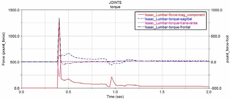
[5]   Ullrich, Peter F. "Lumbar Herniated Disc." Spine-Health. 15 Mar. 2001. 23 Apr. 2008.(http://www.spine-
      health.com/Conditions/Herniated-Disc/Lumbar-Herniated-Disc.html).

[6]   "Lumbar Spinal Stenosis." http://www.neurosurgerytoday.org/what/patient_e/lumbar.asp.Aug. 2005. 23 Apr.
      2008 (http://www.neurosurgerytoday.org/what/patient_e/lumbar.asp).

[7]   "Family Doctor." Vertebroplasty for Spine Fracture Pain. Apr. 2003. 23 Apr. 2008
      (http://familydoctor.org/online/famdocen/home/articles/748.html).

[8]   "Spinal Cord Injury." Paralysis. 23 Apr. 2008.
      (http://www.paralysis.org/site/c.erJMJUOxFmH/b.1293655/k.CF13/Spinal_Cord_Injury.htm)

[9]   "Lifemodeler: Bringing Simulation to Life." 2005. 23 Apr. 2008 (http://www.lifemodeler.com/).

[10] Nahum, Alan M., and John W. Melvin. Accidental Injury. 2nd ed. Springer, 2001.

[11] Aruna, Rajeshwari N., and S Ranjangam. "Transmission of the Weight through the Neutral Arch of Lumbar
     Vertebrae in Man." Journal of the Anatomical Society of India 2003

[12] "Residential Construction." OSHA. 30 Apr. 2007. 23 Apr. 2008
     (http://www.osha.gov/doc/jobsite/#Fall%20Protection1).

[13] "Prevention of Slips, Trips and Falls." CCOHS. 10 June 1999. 23 Apr. 2008
     (http://www.ccohs.ca/oshanswers/safety_haz/falls.html).

[14] "Falls: Construction Fall Protection." Mastery Technologies. 23 Apr. 2008
     (http://www.masterytech.com/productpage.php?product_id=clmicfpr).

Biography
Ha Van Vo
Dr. Ha Van Vo is an Assistant Professor in the Department of Biomedical Engineering and Physician, Mercer
University, Macon, GA. His main teaching and clinical research focus on sport medicine biomechanics, accidental
injury biomechanics, rehabilitation engineering, medical devices, laser guide for surgery, orthopedic implants, and
biomedical mater

R. Radharamanan
Dr. R. Radharamanan is a professor in the Department of Mechanical and Industrial Engineering at Mercer
University in Macon, Georgia. He has thirty five years of teaching, research, and consulting experiences. His
previous administrative experiences include: President of International Society for Productivity Enhancement
(ISPE), Acting Director of Industrial Engineering as well as Director of Advanced Manufacturing Center at
Marquette University, and Research Director of CAM and Robotics Center at San Diego State University. His
primary research and teaching interests are in the areas of manufacturing systems (CAD/CAM and Robotics),
modeling and simulation, quality engineering, and product and process development. He has organized and
chaired/co-chaired five international conferences on CAD/CAM, Robotics and Factories of the Future, and
organized and chaired one regional seminar on Operations Research. He has received two teaching awards, several
research and service awards in the United States and in Brazil. His professional affiliations include ASEE, IIE,
ASQ, SME, ASME, and ISPE.

                                    2009 ASEE Southeast Section Conference
You can also read