Giga-Cycle Fatigue Behavior of the Nuclear Structure of 316L Weldments
←
→
Page content transcription
If your browser does not render page correctly, please read the page content below

ORIGINAL RESEARCH
                                                                                                                                           published: 23 July 2021
                                                                                                                                  doi: 10.3389/fenrg.2021.696608

                                           Giga-Cycle Fatigue Behavior of the
                                           Nuclear Structure of 316L Weldments
                                           Zhihong Xiong, Engao Peng, Lianghua Zeng * and Qirong Xu

                                           School of Industrial Automation, Beijing Institute of Technology, Zhuhai, China

                                           Some components made of 316L stainless steel in nuclear reactors are connected by
                                           welding, and these are under giga-cycle fatigue loading. Therefore, the giga-cycle fatigue
                                           behavior of 316L weldments, which are fabricated by Laser Beam Welding (LBW) and Gas
                                           Tungsten Arc Welding (GTAW), were investigated using an ultrasonic fatigue testing
                                           system. The results indicate that the fatigue strength of LBW-made weldments is
                                           almost the same as that of GTAW-made weldments even though the microstructure
                                           and mechanical properties of the weldments are different. For the LBW-made specimens,
                                           the LBW-induced internal pores with a diameter range of about 89–270 μm were observed
                                           in the fracture surface. However, an obvious decrease in fatigue life was not observed in
                                           such cases. For the GTAW-made specimens, the quality requirement of the weld seam
                                           has to be more strict to prevent fatigue strength from decreasing. The fatigue failure mode
                                           of the GTAW-made specimens is the same as that of LBW-made specimens in the high-
                        Edited by:         cycle fatigue regime but different in the giga-cycle fatigue regime.
                    Zhang Chunyu,
                                           Keywords: nuclear reactor, giga-cycle fatigue, crack initiation, 316L, weldment
       Sun Yat-Sen University, China
                      Reviewed by:
                           Jinfeng Li,
            Imperial College London,
                                           INTRODUCTION
                     United Kingdom
                        Sam Manuel,
                                           Due to its excellent corrosive resistance, irradiation resistance, and mechanical properties, 316L
      Oak Ridge National Laboratory,       austenitic stainless steel (316L) is widely used in the fabrication of nuclear components, which are
                       United States       usually connected by welding. These components usually suffer from giga-cycle loading during their
                  *Correspondence:
                                           service life, which can lead to catastrophic nuclear accidents after a certain period of time (Naoe et al.,
                      Lianghua Zeng        2015; Han et al., 2016). Therefore, the knowledge of the fatigue properties of these weldings is very
                  zhuhai09@sina.com        important to the design of components in the nuclear industry. The study of giga-cycle fatigue
                                           behavior of the 316L weldments is then necessary for the operation and lifetime management of the
                    Specialty section:     nuclear plants.
         This article was submitted to        It has been reported that the fatigue behavior in the giga-cycle regime is different from that
                       Nuclear Energy,     in the high-cycle fatigue regime (Ping et al., 2015; Su et al., 2017). In the giga-cycle fatigue
               a section of the journal    regime, the conventional fatigue limit disappeared and the fatigue cracks initiate from the
         Frontiers in Energy Research
                                           internal defect (such as pores, inclusions, and so on) due to the localized stress or strain
             Received: 17 April 2021       concentration. A typical feature of giga-cycle fatigue, that is the so-called fish-eye, can be
            Accepted: 01 June 2021
                                           observed on the fracture surface. It is proposed that the characteristics of weld microstructures
            Published: 23 July 2021
                                           have a significant influence on the fatigue behavior of weldments (Ko, 1989; Yoshihisa and
                             Citation:     Raman, 2000; Iwata et al., 2006; Basu et al., 2013). The fatigue cracks usually initiate from
   Xiong Z, Peng E, Zeng L and Xu Q
                                           subsurface or internal detects caused by welding in the giga-cycle fatigue regime. The
(2021) Giga-Cycle Fatigue Behavior of
               the Nuclear Structure of
                                           reduction in the fatigue strength is caused by the existence of welding defects and a soft
                     316L Weldments.       zone along with the welds (Deng et al., 2016; Hong and Sun, 2017; Zhang et al., 2018).
         Front. Energy Res. 9:696608.         So far, there are many kinds of commercial welding methods, such as Laser Beam Welding
      doi: 10.3389/fenrg.2021.696608       (LBW), Gas Tungsten Arc Welding (GTAW), Submerged-Arc Welding, and so on. In general,

Frontiers in Energy Research | www.frontiersin.org                                 1                                         July 2021 | Volume 9 | Article 696608
Xiong et al.                                                                                                                 Giga-Cycle Fatigue of 316L

                                                                            FIGURE 2 | Schematic diagram of the fatigue specimen (unit: mm).

  FIGURE 1 | Optical microstructure of the base metal.

the microstructure and mechanical properties of the weld
seam are closely related to welding methods. For example, in
the case of LBW, it is difficult to completely eradicate the pore
due to the metal evaporation caused by the high energy
density and protection gas captured by high cooling rate
(Errico et al., 2020). And the fine grains are usually formed in
the weld seam, leading to high hardness (Xiong et al., 2019a),
which is different from the much lower hardness distributed
in the weld seam induced by the much coarse grains in the
case of GTAW (Xiong et al., 2019b). The size of the heat-
affected zone of LBW-made weldment is also relatively
                                                                            FIGURE 3 | Fatigue strength of the weldments made by BLW and
smaller than that of GTAW-made weldment (Lee et al., 2014).
                                                                            GTAW.
    Although some investigations on the giga-cycle fatigue
behavior of 316L base metal and weldment have been done
(Carstensen et al., 2002; Naoe et al., 2015, 2018; Xiong et al.,
2019b), the fatigue data of 316L, especially of the 316L weldment,         of 319 MPa, 614 MPa, and 183, respectively) was selected as the
is still insufficient. Besides, there have been very few studies thus       base metal, and its representative austenitic microstructure is
far pertaining to how the welding method affects the giga-cycle            shown in Figure 1.
fatigue behavior of 316L.                                                     The details of LBW and GTAW can be referred to in our
    Therefore, to clarify the effects of the weld method on the            previous report (Xiong et al., 2019a; Xiong et al., 2019b). The
fatigue behavior of the weldments, the giga-cycle fatigue                  specimens used for the fatigue test were machined following the
behaviors of 316L weldments fabricated by LBW and by                       geometry shown in Figure 2. Before fatigue testing, each
GTAW respectively were investigated by an ultrasonic fatigue-              specimen surface was polished along the axial direction using
testing machine in this research. Thereafter, the fatigue strength         the 1,200# abrasive paper.
and crack initiation mechanisms of the LBW-made weldments
and the GTAW-made weldments are compared with each other.                  Ultrasonic Fatigue Test
The fatigue fracture surface was investigated through Scanning             The ultrasonic fatigue tests were conducted at Northwestern
Electron Microscopy (SEM) to clarify the fatigue crack initiation          Polytechnical University (Xian, China) with a stress ratio of −1
mechanism.                                                                 at the frequency of 20 kHz. The test was manually stopped
                                                                           when the number of the fatigue cycles reached up to 109. In
                                                                           order to prevent the increase in the specimen temperature due
EXPERIMENT PROCEDURE                                                       to the high strain rate deformation, not only a periodic
                                                                           loading/resting interval was applied during the ultrasonic
Materials and Specimens                                                    fatigue test, but also blasts of cold air were blown to the
In this study, 316L austenitic stainless steel (or ASTM A240, with         specimen surface. More details about the ultrasonic fatigue
the yield strength, ultimate tensile strength, and Vickers hardness        test can be found in the literature (Stanzl-Tschegg, 2014). The

Frontiers in Energy Research | www.frontiersin.org                     2                                           July 2021 | Volume 9 | Article 696608
Xiong et al.                                                                                                                   Giga-Cycle Fatigue of 316L

TABLE 1 | Maximum diameter of the internal pore for the LBW-made weldments.       influence factors that have to be considered: one is the
Stress amplitude (MPa)        Number of cycles to    Maximum diameter of          property of the weld seam, such as grain size, morphology,
                                   failure             the internal pore          and hardness, and the other is the welding defects, such as
                                                              (μm)                pores and poor fusion.
                                                                                     For the GTAW-made weldments, there is no pronounced
230                                 1.82×10⁷                  111.1
230                                 7.93×10⁷                  166.1               difference in microstructure and hardness between weld seam
240                                 1.01×10⁷                   123                and base metal, therefore, the welding process maybe has no clear
240                                 5.22×10⁸                  246.4               side effect on fatigue strength. It can be deduced that the fatigue
250                                 1.00×10⁷                  150.6               strength should be weakened if there were welding defects in the
260                                 5.08×10⁷                  178.6
280                                 2.16×10⁷                  271.7
                                                                                  weld seam.
300                                 2.71×10⁷                   89.3                  For the LBW-made weldments, the localized temperature is
                                                                                  very high due to the high energy density of the heat source,
                                                                                  leading to metal evaporation. Meanwhile, the cooling rate of
                                                                                  the fusion metal is extremely high so that the protection gas
fracture surfaces of the fatigued specimens were characterized                    cannot escape and is captured by the melted metal during
by using SEM to reveal the fatigue crack initiation and                           solidification. Thus, it is difficult to completely eradicate the
propagation mechanism.                                                            pore formed during laser welding. It is revealed that the
                                                                                  existing welding flaws or inclusions are the favorite sites for
                                                                                  crack initiation, and most of the fatigue failure occurs in the
RESULTS AND DISCUSSION                                                            welding part, resulting in the decrease in the fatigue strength
                                                                                  (Yoshihisa and Raman, 2000; Chandra et al., 2013; Stanzl-
Fatigue Strength of the Weldments Made by                                         Tschegg, 2014). Hence, the welding defects existing in the weld
LBW and GTAW                                                                      are likely to do harm to the fatigue strength. On the other hand,
The results of fatigue strength measurements for the weldments                    refined crystalline strengthening, which is caused by the
made by LBW and GTAW are presented in Figure 3.                                   extremely high cooling rate, can enhance the fatigue
    It indicates that fatigue failure occurs in the very high cycle               strength of the weld seam. This means the existence of fine
fatigue regime and the fatigue strength of the LBW-made                           grains along the weld seam may compensate for the harmful
weldment are almost the same as those of the GTAW-made                            effects of the existence of some welding defects at a certain size
weldment, although the microstructure and the properties of the                   near the weld seam made by LBW, without decreasing the
weld seam are different, as reported in the author’s previous                     fatigue strength.
studies (Xiong et al., 2019a; Xiong et al., 2019b).                                  It is well-known that the main pipe connected by GTAW of
    In the case of GTAW, both base metal and weld seam exhibit                    primary circuit in the nuclear power plant is the channel to
typical austenitic equiaxed grains with a similar average grain size              maintain and restrict the coolant circulation flow. It is closed
of about 40 μm and a similar hardness. No distinct welding defect                 with high temperature, high pressure, and radioactive coolant,
is observed.                                                                      which plays an important role in ensuring the safety and
    In the case of LBW, a fine dendrite structure is preferably                    normal operation of the reactor. These components usually
formed at the center of the weld seam, resulting in the highest                   suffer from cyclic loading due to flow-induced vibrations,
hardness. Conversely, coarse columnar crystals can be found                       internal pressure, and thermal stress caused by temperature
at the edge of the weld line, resulting in lower hardness.                        change during the service life of the reactors. Therefore, the
Besides, some pores are observed in the weld seam. Table 1                        service life of the reactor strongly depends on the fatigue life of
shows the diameter of the internal pore for the LBW-made                          the weldment, and the fatigue life of the weldment depends on
weldments. It indicates that the maximum diameter of the                          the welding process and quality. According to the above
internal pores caused by laser welding is in the range of about                   discussions, to prevent the decrease in the fatigue strength
89–270 μm. However, a clear decrease in fatigue life was not                      of the weldments, the quality requirement for the weld seam
observed in such cases. That is, the fatigue life of the LBW-                     made by GTAW has to be more strict than that for the LBW-
made weldment with internal pore, whose diameter is smaller                       made weld seam. In other words, the fatigue life of the
than 270 μm, is not diminished compared to that of GTAW-                          GTAW-made weldment is more sensitive to internal
weldments.                                                                        defects caused by welding than that of the LBW-made
    H.N. Ko shows that the fatigue strength increases as the grain                weldment. For example, if both GTAW- and LBW-made
size decreases (Ko, 1989). Besides, the fatigue strength can be                   weldments contain internal pores with a diameter of
roughly evaluated by tensile strength and hardness. The higher                    100 μm, the fatigue life of GTAW-made weldments might
the tensile strength and hardness, the higher the fatigue strength                decrease notably, but that of LBW-made weldment would not.
is (Casagrande et al., 2011). Furthermore, the fatigue strength of                Comparing to GTAW-made weldment, the safety factor of
the weldments is weakened due to the existing welding defects                     LBW-made weldment is higher. That is, from the viewpoint
(Yoshihisa and Raman, 2000; Iwata et al., 2006).                                  of fatigue strength, laser welding seems to be a potential
    Therefore, to clarify the effects of the welding process on                   alternative to replace GTAW used in nuclear reactor design
the fatigue strength of the weldments, there are two kinds of                     and construction.

Frontiers in Energy Research | www.frontiersin.org                            3                                      July 2021 | Volume 9 | Article 696608
Xiong et al.                                                                                                                                 Giga-Cycle Fatigue of 316L

  FIGURE 4 | Fracture surface of the specimens (GTAW) (A) failed under 320 MPa at 1.53×10⁵ cycles (Xiong et al., 2019b) (B) failed under 250 MPa at 4.3×10⁷
  cycles.

  FIGURE 5 | Fracture surface of the specimen (LBW) tested at 340 MPa failed at 1.84×10⁵ cycles. (A) overview of the fracture surface and (B) enlargement of the
  marked rectangle in (A).

Crack Initiation and Propagation                                                        specimen is shown in Figure 5. This is similar to the failure mode
Mechanism                                                                               of the specimens made by GTAW. In addition, the failure of
All of the fracture surfaces of the fatigue-tested specimens were                       several specimens is caused by the internal pores that are formed
examined by SEM. There are two fracture modes. One is that the                          during laser welding, as shown in Figure 6.
fatigue cracks are initiated from the specimen surface due to                               In the giga-cycle fatigue regime, the fatigue failure mode of
crystal slip. The other one is that the fatigue cracks are initiated                    LBW sample is different from that in the high-cycle fatigue
due to internal defects.                                                                regime and the specimens made by GTAW. Most of the
    For the weldments made by GTAW, as reported in the                                  fatigue failure occurred is due to the internal or subsurface
previous paper (Xiong et al., 2019b), all of the specimens                              crack initiation. A typical internal crack initiation failure
failed due to the surface crack initiation; no matter what kind                         mode, for the specimen tested at 260 MPa failed at 5.08×10⁷
of fatigue regime they are in, high-cycle fatigue regime or giga-                       cycles, is presented in Figure 7.
cycle fatigue regime and multiple crack initiation sites can be                             A very famous phenomenon for the internal defects causing
recognized. Figure 4 presents the typical surface crack initiation                      giga-cycle fatigue failure, i.e., fish-eye, is observed in the
failure modes in the high- and giga-cycle fatigue regimes,                              crack initiation and propagation area, as shown in
respectively. As shown in Figure 4B, fatigue cracks initiate at                         Figure 7A, and a clearer appearance is presented in
the surface and then propagate inward, resulting in the formation                       Figure 7B. As shown in Figure 7C, at the center of the
of a smooth semi-elliptical area.                                                       fish-eye is the origin of a fatigue crack, i.e., a pore
    For the high-cycle fatigue test of weldments made by LBW, the                       introduced by LBW. After the crack initiation, it
fatigue failure is mostly caused by the surface crack initiation with                   propagates along the direction perpendicular to the
multiple crack initiation sites (a typical fracture surface of the                      tangential of the circumference of the pore, and then a

Frontiers in Energy Research | www.frontiersin.org                                  4                                              July 2021 | Volume 9 | Article 696608
Xiong et al.                                                                                                                                 Giga-Cycle Fatigue of 316L

  FIGURE 6 | Fracture surface of the specimen (LBW) tested at 380 MPa failed at 7.15×10⁵ cycles. (A) overview of the fracture surface and (B) enlargement of the
  marked rectangle in (A).

  FIGURE 7 | Fracture surface of the specimen (LBW) tested at 260 MPa failed at 5.08×10⁷ cycles. (A) overview of the fracture surface, (B) enlargement of the
  marked rectangle in (A,C) enlargement of the marked rectangle in (B,D) enlargement of the marked rectangle in (C).

rough area called fine-granular area [FGA, see Figure 7D] is                                 It has been proved that fatigue cracks prefer nucleating and
formed around the pore. Furthermore, outside of the FGA is a                            propagating on specimen surfaces due to their geometric-
bright and relatively flat area, which is related to a different                         mechanical conditions compared to the interior region. The
crack propagation rate.                                                                 fatigue failure is usually caused by the gradual growth of
   In general, the fatigue cracks can initiate from both the                            microcracks originated from slip bands formed on the
specimen surface and the interior, which is the result of the                           specimen surface (Forsyth, 1957; Suresh, 1998). Therefore,
competition between the stress concentration caused by surface                          when the specimen is under a high-stress amplitude, which is
defects and that caused by interior defects. When the                                   higher than the threshold value for persistent slip band (PSB)
concentrated stress caused by internal defects is higher                                formation, i.e., in the high-cycle fatigue regime, the fatigue cracks
enough, the fatigue crack would initiate from the interior.                             usually originate from the specimen surface, as presented in
Otherwise, it initiates from the surface (Xin, 2010).                                   Figure 4 and Figure 5. However, if the stress caused by

Frontiers in Energy Research | www.frontiersin.org                                  5                                              July 2021 | Volume 9 | Article 696608

Xiong et al.                                                                                                                               Giga-Cycle Fatigue of 316L

  FIGURE 8 | Fracture surface of the specimen (LBW) tested at 250 MPa failed at 5.14×10⁸ cycles. (A) overview of the fracture surface, (B) enlargement of the
  marked rectangle in (A).

  FIGURE 9 | The origins of a typical multiple cracks for the specimen
  (LBW) failed at 1.82×10⁷ cycles.
                                                                                       FIGURE 10 | Relationship fracture site and the number of cycles to
                                                                                       failure.

interior defects is high enough, as shown in Figure 6, the fatigue
cracks can also initiate from the interior pores.
    It has been reported that, in the giga-cycle fatigue regime, the                  accumulation of slightly irreversible random slip on the
fatigue crack initiation mechanism is different from that in the                      surface defects, even the stress level is lower than the
high-cycle fatigue regime. The fatigue cracks in the high-cycle                       threshold value for PSB formation (i.e. in the giga-cycle
fatigue regime usually initiate from internal defects or inclusions                   fatigue regime). Therefore, in the case of specimens made by
for many kinds of materials, such as high-strength steel and                          GTAW, there are no obvious welding defects in the weld seam
various alloys (Li, 2012; Krewerth et al., 2013; Bathias and Wang,                    due to the well-controlled weld quality. All of the specimens fail
2014; Grigorescu et al., 2016; Hong et al., 2016). Similar to that, in                due to the accumulation of slightly irreversible random slip on the
this research, most of the fatigue cracks also originate from the                     surface defects in the giga-cycle fatigue regime. This is different
internal defects induced by LBW; only one fatigue failure                             from the case of the LBW-made specimen.
occurred due to the surface crack initiation (as shown in                                 Furthermore, Ma et al. (Ma et al., 2010) found most of the
Figure 8). This is similar to the failure mode of the specimens                       fatigue failures were caused by multiple-crack origins in high-
made by GTAW.                                                                         cycle fatigue regimes while by single crack origin in giga-cycle
    As proposed by Mughrabi (Mughrabi, 1999), for the materials                       fatigue regimes. The number of cracks origins decreases with the
without internal inclusions or with small inclusions, the fatigue                     increase in fatigue life. Because most of the fatigue failure is
cracks also can initiate from specimen surface due to the                             related to the PSB formation in the high-cycle fatigue regime

Frontiers in Energy Research | www.frontiersin.org                                6                                             July 2021 | Volume 9 | Article 696608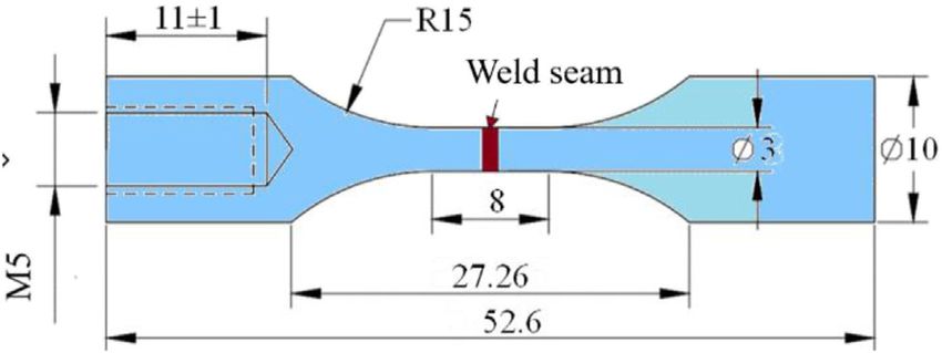
Xiong et al.                                                                                                               Giga-Cycle Fatigue of 316L

(high stress level), the octahedral slip systems can be activated in        investigated by using the ultrasonic fatigue testing system. The
more than one surface grain at different locations in the case of           following conclusions have been drawn.
localized high stress, leading to multiple crack origins (Suresh,               Firstly, the fatigue strength of weldments made by LBW is
1998; Chaussumier et al., 2010). However, as shown in Figure 9,             almost the same as that of weldments made by GTAW, although
the multiple crack origins for some LBW-made specimens are                  the microstructure and properties of the weldments were
also observed in the giga-cycle fatigue regime, resulting from the          different. For the LBW-made specimen, it allows the existence
stress or strain concentration caused by the LBW-induced pore               of some welding defects at a certain size (less than 270 μm) in
cluster.                                                                    weld seam made by LBW, without decreasing the fatigue strength.
                                                                            For the GTAW-made specimens, the quality requirement of the
Fracture Site                                                               weld seam has to be more strict than that by LBW to prevent the
Figure 10 shows the relationship between the distance of fracture           decrease in the fatigue strength.
site to weld center and the number of cycles to failure. The                    Secondly, in the high cycle fatigue regime, the fatigue failure
distance of fracture site to weld center is measured through                mode of the GTAW-made specimens is the same as that of LBW-
careful observation of the fracture surface. The weld bonds of              made specimens, i.e., most of the specimens failed due to the
the GTAW-made and LBW-made weldment are represented by a                    surface crack initiation. In the giga-cycle fatigue regime, all of the
solid line and dash line, respectively. For GTAW-made                       specimens prepared using GTAW are failed due to the surface
specimens, the fatigue failure occurs at base metal (BM) if the             crack initiation, while internal defects are the primary reason to
distance value is larger than 1 mm, otherwise, the specimen failed          induce the failure of LBW-made samples.
at weld metal (WM). For LBW-made specimens, the distance to                     In a word, LBW has some advantages in terms of fatigue
distinguish BM and WM is 0.8 mm. It should be noted that the                resistance compared with GTAW. LBW seems to be a
width of the weld seam for GTAW-made and LBW-made                           potential alternative process to replace GTAW used in the
specimens are 2 and 1.6 mm, respectively.                                   nuclear reactor design and construction. However, the
    It can be seen that the fracture location differs between the           service environment of the reactor components is very
fatigued GTAW-made and LBW-made specimens. For the                          complex. Besides the fatigue resistance of the weldment,
GTAW-made specimen, the fatigue fracture site is                            many other properties (corrosion resistance, irradiation
independent of the number of cycles to failure. Some of the                 resistance, and stress-corrosion resistance amongst other
specimens fail at the BM, and some of them fail at WM. That is,             things) have to be considered and investigated during
the fracture sites are distributed randomly. For the LBW-made               reactor design and construction.
specimen, it seems that the fracture site is related to the number of           Furthermore, pore clusters were observed in the fracture
cycles to failure. The fracture sites are distributed randomly in the       surface, which might have an influence on the giga-cycle
high cycle fatigue regime. This is similar to the case of the               fatigue behavior. Therefore, further investigation on the effect
GTAW-made specimen. However, in the giga-cycle fatigue                      of pore cluster characteristics (the maximum size, distribution,
regime, most of the specimens fail at WM except one specimen.               number of pores, and so on) on fatigue behavior has to be
    As discussed in the previous section, for the GTAW-made                 conducted.
specimen, all of the specimens failed due to the surface crack
initiation, regardless of the number of cycles to failure. As the
well-controlled welding process, there is no obvious welding                DATA AVAILABILITY STATEMENT
defect at the weld seam. Besides, the BM and WM should
have the same surface condition. This indicates they should                 The raw data supporting the conclusion of this article will be
have equal potential for fatigue failure. Therefore, fatigue crack          made available by the authors, without undue reservation.
randomly initiates at BM and WM, i.e., the fracture sites are
randomly distributed. For the LBW-made specimen, similarly,
the fracture site distributes randomly in the high-cycle fatigue            AUTHOR CONTRIBUTIONS
regime. In the giga-cycle fatigue regime, fatigue crack usually
originates from the internal pores caused by welding, i.e., the             ZX carried out the experimental works, analysis and writing. LZ
specimen fracture at WM. In a word, the transition of fracture site         carried of the analysis of the microstructure and hardness of the
for the LBW-made specimen among different parts of the welds is             weldment. QX carried out the analysis of the fatigue fracture
related to the transition of fatigue failure mode.                          surface. EP carried out some experiments.

CONCLUSION AND PROSPECT                                                     FUNDING
In this research, the giga-cycle fatigue behavior of the 316L               This research was funded the Natural science foundation of the
weldment fabricated by GTAW and by LBW has been                             Guangdong province, Grant no. 2018A030310102.

Frontiers in Energy Research | www.frontiersin.org                      7                                        July 2021 | Volume 9 | Article 696608
Xiong et al. Giga-Cycle Fatigue of 316L
REFERENCES Ma, X.-F., Duan, Z., Shi, H.-J., Murai, R., and Yanagisawa, E. (2010). Fatigue
and Fracture Behavior of Nickel-Based Superalloy Inconel 718 up to the
Very High Cycle Regime. J. Zhejiang Univ. Sci. A. 11, 727–737.
Basu, K., Das, M., Bhattacharjee, D., and Chakraborti, P. C. (2013). Effect of Grain doi:10.1631/jzus.a1000171
Size on Austenite Stability and Room Temperature Low Cycle Fatigue Mughrabi, H. (1999). On the Life-Controlling Microstructural Fatigue
Behaviour of Solution Annealed AISI 316LN Austenitic Stainless Steel. Mechanisms in Ductile Metals and Alloys in the Gigacycle Regime. Fatigue
Mater. Sci. Technol. 23, 1278–1284. doi:10.1179/174328407X179575 Fracture Eng. Mater. Structures 22, 633–641. doi:10.1046/j.1460-
Bathias, C., and Wang, C. (2014). Initiation from Low Cycle Fatigue to Gigacycle 2695.1999.00186.x
Fatigue. AMR 891-892, 1419–1423. doi:10.4028/www.scientific.net/amr.891- Naoe, T., Xiong, Z., and Futakawa, M. (2016). Gigacycle Fatigue Behaviour of
892.1419 Austenitic Stainless Steels Used for Mercury Target Vessels. J. Nucl. Mater. 468,
Carstensen, J. V., Mayer, H., and Brøndsted, P. (2002). Very High Cycle Regime 331–338. doi:10.1016/j.jnucmat.2015.07.040
Fatigue of Thin Walled Tubes Made from Austenitic Stainless Steel. Fatigue Naoe, T., Xiong, Z., and Futakawa, M. (2018). Temperature Measurement for In-
Fract Eng. M 25, 837–844. doi:10.1046/j.1460-2695.2002.00554.x Situ Crack Monitoring under High-Frequency Loading. J. Nucl. Mater. 506,
Casagrande, A., Cammarota, G. P., and Micele, L. (2011). Relationship between 12–18. doi:10.1016/j.jnucmat.2017.12.019
Fatigue Limit and Vickers Hardness in Steels. Mater. Sci. Eng. A 528, Ping, Z., Gao, G., Misra, R. D. K., and Bai, B. (2015). Effect of Microstructure
3468–3473. doi:10.1016/j.msea.2011.01.040 on the Very High Cycle Fatigue Behavior of a Bainite/martensite
Chandra, S. K., Shankar, V., Mariappan, K., Sandhya, R., and Chakraborty, P. C. (2013). Multiphase Steel. MATER. SCI. ENG. A. 630, 1–7. doi:10.1016/
Effect of Strain Rate on the Low Cycle Fatigue Behavior of 316L(N) Stainless Steel j.msea.2015.02.015
Weld Joints. Proced. Eng. 55, 176–180. doi:10.1016/j.proeng.2013.03.239 Stanzl-Tschegg, S. (2014). Very High Cycle Fatigue Measuring Techniques. Int.
Chaussumier, M., Shahzad, M., Mabru, C., Chieragatti, R., and Rezaï-Aria, F. J. Fatigue 60, 2–17. doi:10.1016/j.ijfatigue.2012.11.016
(2010). A Fatigue Multi-Site Cracks Model Using Coalescence, Short and Long Su, H., Liu, X., Sun, C., and Hong, Y. (2017). Nanograin Layer Formation at Crack
Crack Growth Laws, for Anodized Aluminum Alloys. Proced. Eng. 2, 995–1004. Initiation Region for Very-High-Cycle Fatigue of a Ti-6Al-4V alloy. Fatigue
doi:10.1016/j.proeng.2010.03.108 Fract Engng Mater. Struct. 40, 979–993. doi:10.1111/ffe.12562
Deng, C., Wang, H., Gong, B., Li, X., and Lei, Z. (2016). Effects of Microstructural Suresh, S. (1998). Fatigue of Materials. Cambridge: Cambridge University Press.
Heterogeneity on Very High Cycle Fatigue Properties of 7050-T7451 Aluminum doi:10.1017/cbo9780511806575
alloy Friction Stir Butt Welds. Int. J. Fatigue 83, 100–108. doi:10.1016/ Xin, L. S. (2010). Very High Cycle Fatigue Properties of High Strength Steels: Effects
j.ijfatigue.2015.10.001 of Nonmetallic Inclusions. BeiJing: Metallurgical Industry Press.
Errico, V., Campanelli, S. L., Angelastro, A., Mazzarisi, M., and Casalino, G. (2020). Xiong, Z. H., Ma, X. F., and Qi, X. Y. (2019a). Very High Cycle Fatigue
On the Feasibility of AISI 304 Stainless Steel Laser Welding with Metal Powder. Behaviour of the 316L Weldment Fabricated by Laser Butt-Welding. IOP
J. Manufacturing Process. 56, 96–105. doi:10.1016/j.jmapro.2020.04.065 Conf. Ser. Mater. Sci. Eng. 538, 012025. doi:10.1088/1757-899X/538/1/
Forsyth, T. (1957). Thomas Forsyth to Lewis Cass, St. Louis October 24, 1831: 012025
Draper Mss. 6T152-164. Ethnohistory 4, 198–202. doi:10.2307/480716 Xiong, Z., Wei, D., Wang, H., Shi, H.-J., and Ma, X. (2019b). Fatigue Behavior of
Grigorescu, A. C., Hilgendorff, P.-M., Zimmermann, M., Fritzen, C.-P., and Christ, 316 L Stainless Steel Weldment up to Very-High-Cycle Fatigue Regime. Mater.
H.-J. (2016). Cyclic Deformation Behavior of Austenitic Cr-Ni-Steels in the Res. Express 6, 076514. doi:10.1088/2053-1591/ab1197
VHCF Regime: Part I - Experimental Study. Int. J. Fatigue 93, 250–260. Yoshihisa, E., and Ganesh Sundara Raman, S. (2000). Thermomechanical and
doi:10.1016/j.ijfatigue.2016.05.005 Isothermal Fatigue Behaviour of Type 316 Stainless Steel Base Metal, weld
Han, Y., Mei, J., Peng, Q., Han, E.-H., and Ke, W. (2016). Effect of Electropolishing on Metal, and Joint. Sci. Technol. Welding Joining 5, 174–182. doi:10.1179/
Corrosion of Nuclear Grade 316L Stainless Steel in Deaerated High Temperature 136217100101538173
Water. Corrosion Sci. 112, 625–634. doi:10.1016/j.corsci.2016.09.002 Zhang, W. C., Zhu, M. L., Wang, K., and Xuan, F. Z. (2018). Failure Mechanisms
Hong, Y., Liu, X., Lei, Z., and Sun, C. (2016). The Formation Mechanism of and Design of Dissimilar Welds of 9%Cr and CrMoV Steels up to Very High
Characteristic Region at Crack Initiation for Very-High-Cycle Fatigue of High- Cycle Fatigue Regime. Int. J. Fatigue, 367–376. doi:10.1016/
Strength Steels. Int. J. Fatigue 89, 108–118. doi:10.1016/j.ijfatigue.2015.11.029 j.ijfatigue.2018.04.032
Hong, Y., and Sun, C. (2017). The Nature and the Mechanism of Crack Initiation and
Early Growth for Very-High-Cycle Fatigue of Metallic Materials - an Overview. Conflict of Interest: The authors declare that the research was conducted in the
Theor. Appl. Fracture Mech. 92, 331–350. doi:10.1016/j.tafmec.2017.05.002 absence of any commercial or financial relationships that could be construed as a
Iwata, T., Matsuoka, K., and Kobayashi, Y. (2006). Fatigue Strength of Welded potential conflict of interest.
Joints of SUS316L for Chemical Tankers. Weld World 50, 82–91. doi:10.1007/
BF03263448 Publisher’s Note: All claims expressed in this article are solely those of the authors
Ko, H. N. (1989). Effect of Grain Size on Fatigue Strength of Sintered Al2O3 under and do not necessarily represent those of their affiliated organizations, or those of
Rotary Bending. J. Mater. Sci. Lett. 8, 1438–1441. doi:10.1007/BF00720216 the publisher, the editors and the reviewers. Any product that may be evaluated in
Krewerth, D., Weidner, A., and Biermann, H. (2013). Application of In Situ this article, or claim that may be made by its manufacturer, is not guaranteed or
Thermography for Evaluating the High-Cycle and Very High-Cycle Fatigue endorsed by the publisher.
Behaviour of Cast Aluminium alloy AlSi7Mg (T6). Ultrasonics 53, 1441–1449.
doi:10.1016/j.ultras.2013.03.001 Copyright © 2021 Xiong, Peng, Zeng and Xu. This is an open-access article
Lee, J. H., Park, S. H., Kwon, H. S., Kim, G. S., and Lee, C. S. (2014). Laser, Tungsten distributed under the terms of the Creative Commons Attribution License (CC
Inert Gas, and Metal Active Gas Welding of Dp780 Steel: Comparison of BY). The use, distribution or reproduction in other forums is permitted, provided the
Hardness, Tensile Properties and Fatigue Resistance. Mater. Des. 64 (dec), original author(s) and the copyright owner(s) are credited and that the original
559–565. doi:10.1016/j.matdes.2014.07.065 publication in this journal is cited, in accordance with accepted academic practice.
Li, S. X. (2012). Effects of Inclusions on Very High Cycle Fatigue Properties of High No use, distribution or reproduction is permitted which does not comply with
Strength Steels. Int. Mater. Rev. 57, 92–114. doi:10.1179/1743280411Y.0000000008 these terms.
Frontiers in Energy Research | www.frontiersin.org 8 July 2021 | Volume 9 | Article 696608You can also read