Non-fullerene acceptor organic photovoltaics with intrinsic operational lifetimes over 30 years - Nature
←
→
Page content transcription
If your browser does not render page correctly, please read the page content below

ARTICLE
                  https://doi.org/10.1038/s41467-021-25718-w                 OPEN

                  Non-fullerene acceptor organic photovoltaics with
                  intrinsic operational lifetimes over 30 years
                  Yongxi Li 1, Xiaheng Huang1, Kan Ding1, Hafiz K. M. Sheriff, Jr                                 2,   Long Ye3,4, Haoran Liu5, Chang-Zhi Li5,
                  Harald Ade 3 & Stephen R. Forrest 1,2 ✉
1234567890():,;

                  Organic photovoltaic cells (OPVs) have the potential of becoming a productive renewable
                  energy technology if the requirements of low cost, high efficiency and prolonged lifetime are
                  simultaneously fulfilled. So far, the remaining unfulfilled promise of this technology is its
                  inadequate operational lifetime. Here, we demonstrate that the instability of NFA solar cells
                  arises primarily from chemical changes at organic/inorganic interfaces bounding the bulk
                  heterojunction active region. Encapsulated devices stabilized by additional protective buffer
                  layers as well as the integration of a simple solution processed ultraviolet filtering layer,
                  maintain 94% of their initial efficiency under simulated, 1 sun intensity, AM1.5 G irradiation
                  for 1900 hours at 55 °C. Accelerated aging is also induced by exposure of light illumination
                  intensities up to 27 suns, and operation temperatures as high as 65 °C. An extrapolated
                  intrinsic lifetime of > 5.6 × 10⁴ h is obtained, which is equivalent to 30 years outdoor
                  exposure.

                  1 Departments of Electrical Engineering, Material Science and Engineering, and Physics, University of Michigan, Ann Arbor, MI 48109, USA. 2 Applied Physics

                  Program, University of Michigan, Ann Arbor, MI 48109, USA. 3 Department of Physics and Organic and Carbon Electronics Laboratories (ORaCEL), North
                  Carolina State University, Raleigh, NC 27695, USA. 4 School of Materials Science and Engineering and Tianjin Key Laboratory of Molecular Optoelectronic
                  Sciences, Tianjin University, 300072 Tianjin, China. 5 State Key Laboratory of Silicon Materials, MOE Key Laboratory of Macromolecular Synthesis and
                  Functionalization, Department of Polymer Science and Engineering, Zhejiang University, 310027 Hangzhou, China. ✉email: stevefor@umich.edu

                  NATURE COMMUNICATIONS | (2021)12:5419 | https://doi.org/10.1038/s41467-021-25718-w | www.nature.com/naturecommunications                                 1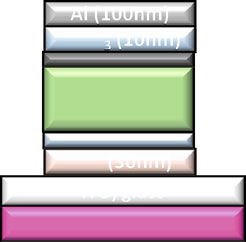
ARTICLE                                                                 NATURE COMMUNICATIONS | https://doi.org/10.1038/s41467-021-25718-w

O
          rganic photovoltaic cells (OPVs) have sparked consider-            dependence on temperature, leading to an extrapolated intrinsic
          able interest in recent years owing to their lightweight,          lifetime, corresponding to a decrease in PCE of 20% from its
          flexibility, low cost, and environmental friendliness. As           initial value, of T80 > 5.6 ×10⁴ h, which is equivalent to 30 years of
distinguished from incumbent solar technologies, OPVs have                   outdoor operation.
shown promise for use in building-integrated energy generating
windows and greenhouses due to their high absorption in the
near infrared while being semitransparent, and importantly,                  Results
neutral optical density in the visible1–7. Recently, ladder-type             To investigate the reliability of NFA-based devices, we choose a
non-fullerene acceptors (NFAs) have led to OPV power conver-                 material system used for semitransparent solar cell modules
sion efficiencies (PCEs) of ~18% in opaque cells, and 10% in                  consisting of the commonly used donor, PCE-10, and an arche-
semitransparent cells with 50% visible transparency8–13.                     type near infrared (NIR) absorbing non-fullerene acceptor, BT-
Although a few reports show that NFA-based solar cells under                 CIC, whose molecular structures are shown in Fig. 1a (see
light-emitting diode (LED) illumination have the potential to                Methods for the nomenclatures of all molecules used in this
reach long operational lifetimes (Supplementary Table 1),                    study). An inverted device was fabricated with the structure:
unfortunately, their ability to withstand use in harsh and realistic         (ITO) / ZnO (30 nm) / PCE-10:BT-CIC (1:1.5, w/w, 80 nm) /
environments (significant ultraviolet (UV) infrared (IR), spectral            MoOx (10 nm) / Al (100 nm). To prevent chemical and mor-
content, and high operating temperatures) over long periods is, as           phological changes at organic/inorganic interfaces over time,
yet, largely unproven14–20. In addition, high efficiency and long             buffer layers are inserted between the BHJ and charge trans-
lifetime have yet to be simultaneously achieved in the same NFA-             porting layers for improving the stability of the contact interface.
based cell. This has led to the belief that short operational life-          As shown in Fig. 1a, several buffer materials are investigated for
times are an intrinsic disadvantage of high efficiency, NFA-based             their influence on device reliability. The performance of the as-
solar cells14,15.                                                            grown devices are listed in Supplementary Table 2 and 3.
   Indeed, a pervasive myth associated with OPVs is that the                 Figure 1b–e and Supplementary Fig. 1-2 shows the evolution of
materials are intrinsically vulnerable to degradation and mor-               the packaged solar cell performance parameters over time under
phological instabilities in the bulk heterojunction (BHJ) over the           simulated AM1.5 G, one sun intensity illumination by Xe-arc
short term21–23. However, this myth is challenged by the very                lamp solar simulator at 55 ± 5 °C for both control and buffer-
long extrapolated lifetimes (27,000 years) recently demonstrated             contained devices. All devices were encapsulated in a glovebox
in an archetype, thermally evaporated fullerene-based material               filled with ultrahigh purity nitrogen (
NATURE COMMUNICATIONS | https://doi.org/10.1038/s41467-021-25718-w ARTICLE
Fig. 1 Device structure, molecular structures, and OPV ageing data under 1 sun simulated AM1.5 G illumination. a Schematic of the device showing
layer thicknesses and compositions (right): molecular structural formulae of the PCE-10 and BT-CIC (left): molecular structural formulae of the cathode
and anode buffer materials. b PCE power conversion efficiency, c VOC Open-circuit voltage, d JSC Short circuit current, and e FF Fill factor, plotted vs. aging
time under 1 sun simulated AM1.5 G illumination for 3000 h with different device architectures (populations of 3–4 devices). The error bars indicate the
1 s.d. uncertainty of each measurement.
Fig. 2 OPV efficiency under accelerated aging conditions. a Normalized PCE plotted vs. aging time under illumination equivalent to 10 ± 1.2, 20 ± 2.5, and
27 ± 3.8 suns. b Normalized PCE plotted vs. aging time under simulated AM1.5 G one sun illumination with temperature of 45 ± 5, 55 ± 5, and 65 ± 5 °C
(populations of 3–4 devices). The error bars indicate the 1 s.d. uncertainty of PCE measurements.
spectrum, 25 °C)28, the cells are exposed to light intensity to up to factor. Figure 2a and Supplementary Fig. 4 show the performance
27 suns using white light-emitting diodes (LEDs, see Methods). characteristics of a population of OPV cells with both IC-SAM
Provided that the effects of temperature and intensity on device and C70 buffer layers aged at equivalent intensities of 10 ± 1.2,
aging are independent, the degradation acceleration factor given 20 ± 2.5, and 27 ± 3.8 suns. To avoid excessive heating at high
by28: intensity, the OPV cells were actively water-cooled to maintain
!γ the temperature at 33 ± 5, 49 ± 5, and 61 ± 5 °C, respectively. We
I test E 1 1 observe that JSC significantly decreases during aging, while VOC
A¼ exp a ð1Þ and FF remain relatively stable. On the other hand, a second
I ref kB T test T a
group of OPV cells with the same structure was aged by elevating
allows for extrapolation to a reference intensity of Iref = 1 sun the cell temperature under simulated AM1.5 G, one sun intensity
when employing an elevated test intensity of Itest, and for deter- illumination (see Methods). The evolution of solar cell perfor-
mining the lifetime at ambient temperature, Ta, for a test done at mance over time is shown in Fig. 2b. We observed that the PCEs
Ttest. Here, Ea is the activation energy for failure, kB is Boltz- of the cells are stable, with no temperature-dependent increase in
mann’s constant, and γ is the intensity-dependent acceleration degradation rate up to 65 ± 5 °C.
NATURE COMMUNICATIONS | (2021)12:5419 | https://doi.org/10.1038/s41467-021-25718-w | www.nature.com/naturecommunications 3ARTICLE NATURE COMMUNICATIONS | https://doi.org/10.1038/s41467-021-25718-w While there are several sources for changes of OPV perfor- morphology with one peak at q = 0.10 nm−1 (corresponding to a mance over time, none is more fundamental than the degradation distance of 63 nm) and another at 0.28 nm−1 (22 nm); see Sup- of the organic molecules comprising the layer structure itself. To plementary Fig. 9, and a summary of the device performance over determine the chemical stability of the BHJ constituents, we time in Table 1. Additionally, the composition of the BT-CIC performed nuclear magnetic resonance (NMR) spectroscopy on molecule in the mixed domains was evaluated from the integrated BT-CIC before and after aging under AM1.5 G one sun illumi- scattering intensity (ISI)29, which scales with the standard nation (see Methods and Supplementary Fig. 5). There is no deviation from the blend composition. This, in turn, is a function change after aging for 60 h, which suggests that the BT-CIC of the relative domain purity. The ISI remains constant over time, molecule itself is stable under light exposure. A similar stability indicating that the bulk morphology of PCE-10:BT-CIC blend was observed for PCE-10; its molecular weight remained film is unchanged. unchanged and no fragments are observed in gel permeation Transmission electron microscopy (TEM) images of thin cross- chromatography spectra throughout the 50 h aging period (Sup- sectional slices of the OPVs without, and with the IC-SAM plementary Fig. 6). The photostability of PCE-10:BT-CIC blend interface buffer are shown in Fig. 3b–d, respectively. We find that film was investigated by UV-Vis spectroscopy (Supplementary the unprotected interface between ZnO and the BHJ appears Fig. 7). The shape and intensity of the exciton absorption spec- broad, which is possibly due to the diffusion of ZnO into the trum shows almost no changes after aging for over 1500 h under organic layer. In contrast, when the IC-SAM is placed between AM1.5 G one sun illumination. This was also confirmed by the ZnO and the BHJ, we observe a sharp boundary between Fourier-transform infrared spectroscopy as shown in Supple- layers that is stable over time. mentary Fig. 8, where no difference was observed between the The absorption loss of encapsulated PCE-10 and BT-CIC on fresh and aged devices. ZnO films aged under high-intensity UV (365 nm LED, 60 suns, The morphological stability of the PCE-10:BT-CIC (1:1.5, w/w) equivalent) is shown Fig. 4a–d. Contrary to previous studies film was further investigated using grazing incidence wide-angle where PCE-10 on ZnO showed no degradation over 1400 h, UV X-ray scattering (GIWAXS), and carbon K-edge resonant soft soaking for ~30 h bleaches the BT-CIC. This is attributed to the X-ray scattering (R-SoXS) as functions of aging under AM1.5 G, photo-oxidation of the exocyclic double bond in BT-CIC that 1 sun intensity illumination. As shown in Fig. 3a, the GIWAXS interrupts the π-conjugation, thus decreasing its absorbance30,31. diffraction profile of the PCE-10:BT-CIC blend film shows a With insertion of the IC-SAM, no bleaching of BT-CIC and PCE- (010) peak in the out-of-plane direction at ~1.8 Å−1, and a (100) 10:BT-CIC blend films is observed, and the intramolecular charge diffraction peak in the in-plane direction at 0.30 Å−1 character- transfer peak maintains both its shape and intensity (Fig. 4c, d istic of BT-CIC. No changes in coherence lengths were observed and Supplementary Fig. 10). The X-ray photoelectron spectra in the diffraction profiles after aging. Further, both fresh and aged (XPS) of the O 1 s core level are shown in Supplementary Fig. 11. PCE-10:BT-IC blends show the same multi-length-scale We find the binding energy of oxygen at the ZnO/IC-SAM Fig. 3 GIWAXS characterization and TEM images. a In-plane (dotted line) and out-of-plane (solid line) sector-averaged profiles extracted from grazing incidence wide-angle X-ray scattering (GIWAXS) patterns; q is the scattering vector. b Transmission electron microscope (TEM) image of cross-sectional slices of a fresh PCE-10:BT-CIC device without an interface buffer layer. c Fresh PCE-10:BT-CIC device with an IC-SAM layer inserted at the ZnO/BHJ interface. d Aged PCE-10:BT-CIC device with an IC-SAM layer inserted at the ZnO/BHJ interface under 27 ± 3.8 suns illumination for 870 h. 4 NATURE COMMUNICATIONS | (2021)12:5419 | https://doi.org/10.1038/s41467-021-25718-w | www.nature.com/naturecommunications
NATURE COMMUNICATIONS | https://doi.org/10.1038/s41467-021-25718-w                                                                       ARTICLE

 Table 1 Morphological parameters extracted from GIWAXS and R-SoXS measurements.

 Sample                        OPP (010) Peak                  IP (100) Peak                 q (nm−1)                Long period (nm)               ISI
 Fresh                         1.60/1.80                       0.30                          0.10                    63                             0.69
 Aged (60 h)                   1.60/1.80                       0.30                          0.10                    63                             0.70
 Aged (3100 h)                 1.59/1.80                       0.30                          –                       –                              –

Fig. 4 Assessment of the stability of the organic/inorganic interface. UV-Vis absorption spectra plotted vs. aging time under ultraviolet illumination with
intensity equivalent to 60 suns of thin film of a PCE-10 on ZnO, b BT-CIC on ZnO, c BT-CIC on ZnO with an IC-SAM buffer, and d PCE-10:BT-CIC on ZnO
with an IC-SAM buffer. X-ray photoelectron spectra of Mo 3d for the fresh device without e 2 nm C70 layer, f aged device without C70 layer, g fresh device
with C70 layer, and h aged device with C70 layer. The Gaussian distributions used to fit the spectrum and the sum of these Gaussians are shown by the
solid lines. The black lines, which are often buried by the summation fit (green lines), correspond to the experimental results.

interface is blue-shifted compared to samples with only ZnO or                  the ZnO induced by exposure to UV illumination, increased
IC-SAM, suggesting that stabilizing chemical bonds are formed                   concentration of defect states due to the penetration of Mo into
between ZnO and IC-SAM. This was further verified by the C 1 s                   the underlying organics (see Supplementary Fig. 15), and NFA
core XPS spectra, where an ester group is identified at the ZnO/                 bond dissociation when exposed to intense or prolonged UV
IC-SAM interface (Supplementary Fig. 12). Such surface passi-                   radiation35,36. As discussed above, a monolayer of IC-SAM sta-
vation results in the reduced photoluminescent (PL) intensity of                bilizes the ZnO surface, thereby preventing photochemical reac-
an oxygen interstitial trap state in ZnO (Supplementary                         tions with the organics. Similarly, an ultrathin C70 layer inserted
Fig. 13)32.                                                                     between the organics and MoOx appears to substantially decrease
   One common source of instability of organic materials is their               anode-BHJ interactions. This is inferred from measurements of
dissociation when exposed to high energy (i.e., UV) radiation22,33,34.          the Mo 3d valence using X-ray photoelectron spectra (XPS) taken
Therefore, we used matrix-assisted laser desorption ionization with             on PCE-10:BT-CIC (1:1.5, w/w, 80 nm)/MoOx (2 nm) and PCE-
time-of-flight mass spectrometry (MALDI-TOF-MS) to investigate                   10:BT-CIC (1:1.5, w/w, 80 nm)/C70 (2 nm)/MoOx (2 nm) films
photostability of BT-CIC by identifying the chemical fragments                  before and after illumination for 250 h under simulated AM1.5 G,
generated during the UV aging. The MALDI-TOF-MS analysis                        one sun intensity irradiation. As shown in Fig. 4e–h, the Mo 3d
shows two new chemical species that exhibit lower mass in com-                  spectra are fit by two 3d doublets and a singlet, corresponding to
parison to BT-CIC, see Supplementary Fig. 14. The peak at a mass-               Mo in three different oxidation states36–38. The peaks at 233.7 eV
to-charge ratio, m/z = 1596.3, possibly originates from the scission            and 236.7 eV correspond to the 3d doublet of Mo6+, those cen-
of the C–O bond out of the thiophene backbone. The electron                     tered at 232.5 eV and 235.6 eV are the 3d doublet of Mo5+, and
donating character of the oxygen atom is known to weaken the C–H                the peak at 229.0 eV is attributed to Mo3+. It is apparent that the
bond, leading to the hydrogen abstraction on the CH2 group (α                   peak intensity of Mo6+ at the MoOx/BHJ interface decreases
position to the oxygen)22. On the other hand, the peak at m/                    compared to the MoOx/2 nm C70/BHJ structure after light
z = 1433.1 corresponds to a fragment with one peripheral phenyl                 soaking. This suggests that the insertion of only 2 nm C70 between
group further removed. This result confirms that the weakest bonds               BHJ and MoOx forms an effective barrier that prevents reduction
in thiophene-based NFAs most susceptible to scission by UV irra-                of the Mo6+ to Mo5+, possibly by preventing the interdiffusion of
diation are the side chain substituents.                                        thiophene-rich BT-CIC into MoOx. The conclusions drawn from
                                                                                these spectroscopic data are consistent with detailed analysis of
                                                                                the as-grown and aged J–V characteristics of OPVs under 1 sun,
Discussion                                                                      simulated AM1.5 G illumination both with, and without the
There are three-primary sources of degradation of PCE-10:BT-                    peripheral buffer layers found in the Supplementary Fig. 16,
CIC cells: photochemical reactions between the organic layers and               where the photogeneration efficiency of the BHJ decreases

NATURE COMMUNICATIONS | (2021)12:5419 | https://doi.org/10.1038/s41467-021-25718-w | www.nature.com/naturecommunications                                  5
ARTICLE NATURE COMMUNICATIONS | https://doi.org/10.1038/s41467-021-25718-w continuously in the control device with no buffer layers. In equivalent UV). The performance of the filtered device retained contrast, the value remains almost constant in the buffered 95% of its initial PCE after 340 h, which is equivalent to 11 years devices, suggesting that the stability of bulk morphology essential of accumulated UV photons from outdoor exposure. In contrast, to a high device reliability is improved by employing buffer layers the PCE of the device lacking the UV filter declined by 66% over and a UV filter39. this same period. To test if the methodology demonstrated in this work could be The UV-filtered devices with both C70 and IC-SAM buffer applied to the other NFA solar cells, we also fabricated devices layers were then subjected to accelerated aging to determine their based on other two archetype NFAs: BT-IC and Y625,40. The stability extrapolated to standard reporting conditions. As shown evolution of solar cell performance over time under simulated in Fig. 6, the normalized PCE is plotted vs. the equivalent 1 sun AM1.5 G one sun illumination is plotted in Supplementary exposure time at intensities ranging from 1 to 27 suns. We find Figs. 17 and 18. Similar to the devices with BT-CIC, the decrease that results at all intensities follow the same trend described by in JSC, VOC, and FF are suppressed in PCE-10:BT-IC when IC- Eq. 1 (shown by the fit line). Given the OPV cells are thermally SAM and C70 are inserted. Moreover, the degradation rate of stable up to at least 65 ± 5 °C, we can assume Ea ≈ 0 under rea- OPV cells with buffer layers is at least 20 times less than in their sonable ranges of temperature around the standard reporting absence without the elimination of UV effects. Additionally, the conditions. Furthermore, from the fit to all data in Fig. 6, we photostability of PM6:Y6 device was investigated9. The perfor- obtain γ = 2.02 ± 0.16. We speculate that the quadradically mance of device retains 90% of its initial value after aging for dependent degradation of the PCE-10:BT-CIC BHJ cells results 500 h under AM1.5 G one sun illumination with a 400 nm long from second-order reactions such as exciton–exciton and pass filter. This preliminary result indicates that NFA-based solar exciton–polaron annihilation41. On the basis of this value of γ, we cells have the potential to meet the market needs of high relia- can define an equivalent 1 sun exposure time for OPV cells aged bility in addition to their high efficiency. at each intensity. Extrapolating these data, we obtain a Since degradation depends on UV light exposure, we solution T80 > 5.6 × 10⁴ h. To convert the lifetimes of the OPV cells into coat a 600 nm-thick ZnO film on the distal surface of the glass outdoor lifetime projections, we assume an average of 5 kW-h/m2 substrate that effectively blocks radiation at wavelengths 30 yr (Methods). Figure 5a shows the transmittance spectra of the fresh outdoor exposure, suggesting that the intrinsic stability of PCE- stand-alone filter, as well as one aged for 1500 h at 1 sun intensity 10:BT-CIC cells can substantially exceed the requirements for in air. Compared to the bare glass substrate, the one comprising almost all practical applications. the ZnO filter exhibits negligible transmission at wavelengths This work demonstrates that NFA-based solar cells have the 400 nm. As a result, ability to achieve long term intrinsic stability under circumstances an OPV with the ZnO filter is significantly more stable that use our innovative buffering and filtering schemes. However, (Fig. 5b–d). The performance of the integrated device under 1 sun to be practical, the cost and stability of encapsulation must also be intensity AM1.5 G illumination retained 94% of its initial PCE considered. Although recent breakthroughs in deposition tech- after 1900 h Supplementary Fig. 19). Additionally, the integrated nology, such as atomic layer deposition (ALD), have led to dra- device is stable under extremely high UV powers (60 suns matic improvements in the barrier to gas penetration, and hence Fig. 5 Characterization of the ZnO UV filter. a UV-Vis absorption spectra of a ZnO UV filter plotted vs. aging time under simulated AM1.5 G 1 sun illumination in air over 65 days. b Current-density-voltage characteristics, and c external quantum efficiency (EQE) spectra of fresh PCE-10:BT-CIC (1:1.5, w/w) devices with a ZnO UV filter, as well as the aged device under simulated AM1.5 G 1 sun illumination. d Normalized PCE plotted vs. aging time under ultraviolet illumination equivalent to 60 suns for more than 350 h with and without ZnO UV filter. The error bars indicate the 1 s.d. uncertainty of PCE measurements. 6 NATURE COMMUNICATIONS | (2021)12:5419 | https://doi.org/10.1038/s41467-021-25718-w | www.nature.com/naturecommunications
NATURE COMMUNICATIONS | https://doi.org/10.1038/s41467-021-25718-w                                                                                               ARTICLE

                                                                                             H-[5,6]fullereno-C60-Ih-[1,9-c]pyrrol-2′-yl)benzoic acid, C60-SAM (1-Material, Dor-
                                                                                             val, CA), C70 SES Research, Houston, TX, US), 4-imidazoleacetic acid hydrochloride
                                                                                             (Sigma–Aldrich, St. Louis, MO, US), N,N′-Di(1-naphthyl)-N,N′-diphenyl-(1,1′-
                                                                                             biphenyl)-4,4′-diamine, NPD, 5,10,15,20-Tetraphenylbisbenz[5,6]indeno[1,2,3-
                                                                                             cd:1′,2′,3′-lm]perylene, DBP, and 2,2’,2”-(1,3,5-Benzinetriyl)-tris(1-phenyl-1-H-ben-
                                                                                             zimidazole), TPBi, Bathophenanthroline, Bphen from Luminescence Technology
                                                                                             Corp., New Taipei City, Taiwan, MoO3 (Acros Organics, Fair Lawn, NJ, US), Zinc
                                                                                             acetate dihydrate (Sigma–Aldrich, St. Louis, US) and Al (Alfa Aesar, Haverhill,
                                                                                             MA, US).

                                                                                             Solar cell fabrication. Prepatterned ITO-coated glass substrates with sheet resis-
                                                                                             tances of 15 Ω/sq were purchased from Luminescence Technology Corp. Prior to
                                                                                             thin-film deposition, the substrate surface was detergent and solvent cleaned with
                                                                                             acetone and isopropanol, followed by CO2 snow cleaning and exposure to
                                                                                             ultraviolet-ozone for 15 min45. The ZnO layer (ca. 30 nm) was spin cast from a
Fig. 6 Aging acceleration factor and extrapolated OPV lifetime.                              ZnO precursor solution onto the substrates and then thermally annealed at 150 °C
Normalized PCE plotted vs. the equivalent 1 sun exposure time, defined as                     for 30 min in air. The IC-SAM was dissolved in methanol with a concentration of
                                                                                             1 mg/ml and spin coated at 4000 rpm for 60 s, followed by thermal annealing at
time (h) multiplied by intensity (suns) raised to the power of 2.02, for OPV                 110 °C for 10 min. Then, the IC-SAM coated substrate was washed with methanol
cells under all illumination conditions used in this work. The data are fit to                to remove the residues. The non-fullerene active layer, PCE-10:BT-CIC (1:1.5 by
an exponential to estimate the time for the PCE to drop to 80% of its initial                weight), was dissolved in chlorobenzene:chloroform (CB:CF, 10:1 by vol.) with a
value, T80, with the best fit shown as a solid line. The error bar indicates the              concentration of 16 mg/ml. The solution was filtered once with a 0.45 μm poly-
                                                                                             tetrafluoroethylene (PTFE) syringe filter prior to use, and then spin-coated onto
1 s.d. uncertainty of the PCE measurements.
                                                                                             the substrate at 2000 rpm for 90 s to achieve a thickness of 80–90 nm. The samples
                                                                                             were transferred into the vacuum chamber connected to glove boxes filled with
improved reliability of organic light-emitting diodes (OLEDs),                               ultrapure N2 (O2, H2O < 0.1 ppm). The C70, MoO3 and Al films were deposited at
such layer growth is slow, and hence ultimately may be prohi-                                0.2 Å /s in a high vacuum chamber with a base pressure of 10−7 torr. The
                                                                                             deposition rates and thicknesses were measured using quartz crystal monitors and
bitively costly28. Furthermore, barrier-coated plastic substrates                            calibrated post-growth by variable-angle spectroscopic ellipsometry. Device areas
are currently more costly to produce than metal foils or ultrathin                           of 2 × 2 mm were defined by the overlap of the ITO anode and the Al cathode with
glass substrates, and they also have compelling advantages such as                           an ultrathin shadow mask (50 µm).
toughness that may ultimately be more important than cost                                        The ZnO UV filter was deposited on the distal end of the glass substrate before
alone28. For transparent OPVs, however, the cost of encapsula-                               the device fabrication. The ZnO layer (ca. 600 nm) was spun cast from a ZnO
                                                                                             precursor solution and followed by thermal annealing at 300 °C for 1 h in air. After
tion can be minimized by inserting the thin-film modules into the                             cooling to the room temperature, the ZnO-coated glasses were cleaned using a
pocket of double-pane windows sealed with inert gas, as is                                   series of the solvents, acetone, and isopropanol, and sonicated 5 mins for each
common practice for insulating windows. The costs for such                                   solvent.
systems have been estimated to be quite attractive26.
   In summary, we demonstrate a solution-processed non-full-                                 Solar cell characterization. The current–density–voltage (J–V) characteristics and
erene, thiophene-based acceptor OPV with requirements of high                                external quantum efficiencies (EQE) of the cells were measured in a glovebox filled
efficiency, low cost, and remarkable operational stability simul-                             with ultrapure N2. The EQE measurements were performed with devices underfilled
taneously achieved. The instability of the NFA solar cells origi-                            by a 200 Hz-chopped monochromated and focused beam from a Xe lamp. The
nates from time-dependent changes at the interfaces between the                              current output from the devices as well as from a reference National Institute of
                                                                                             Standards and Technology (NIST)-traceable Si detector were recorded using a lockin
BHJ and the inorganic charge transporting layers. The changes                                amplifier. Light from a Xe lamp filtered to achieve a simulated AM1.5 G spectrum
are significantly suppressed by insertion of the ultrathin protec-                            (ASTM G173-03) was used as the source for J–V measurements. The lamp intensity
tive buffer layers, IC-SAM and C70, at each side of the BHJ.                                 is varied using neutral-density filters and was calibrated by a Si reference cell certified
Further enhancement is afforded by the integration of a simple                               by National Renewable Energy Laboratory. Each cell was measured under six dif-
                                                                                             ferent light intensities from 0.001 sun to 1 sun (100 mW/cm2). The JSC were cal-
ZnO UV-filter layer to the distal surface of the glass substrate.                             culated from the EQE spectrum, with  5.6 × 10⁴ h is obtained by exposure of light illumination
                                                                                             Device stability measurements. All devices were encapsulated by bonding a glass
intensities up to 27 suns, and operation temperatures as high as                             cover slide to the substrate in a glovebox filled with high purity nitrogen, using an
65 °C. Our results show that NFA-based solar cells have the                                  ultraviolet-curable epoxy. All aging in the light soaking chamber were performed
potential to meet the market needs of high reliability in addition                           on the encapsulated devices in air. The Xe-arc lamp spectrum (see Supplementary
to their high efficiency and potentially low manufacturing costs.                             Fig. 20) was filtered to approximate an AM1.5 G reference, and its intensity was
                                                                                             controlled to provide an output of 1.0 ± 0.1 kW m−2 during the aging period. One
                                                                                             group of packaged devices was aged under open circuit at 55 ± 5 °C, and the
                                                                                             photovoltaic efficiency was periodically recorded under AM1.5 G simulated spec-
Methods                                                                                      trum. A second group of encapsulated devices was mounted on printed circuit
Materials. The non-fullerene acceptors are (4,4,10,10-tetrakis(4-hexylphenyl)-5,11-          boards and connected to a resistor to fix its current and voltage near the maximum
(2-ethylhexyloxy)-4,10-dihydro-dithienyl[1,2-b:4,5b′] benzodithiophene-2,8-diyl)             power operating point. The PCE was recorded every 2 h. For the UV degradation
bis(2-(3-oxo-2,3-dihydroinden-5,6-dichloro-1-ylidene)malononitrile, BT-CIC, and              mechanism studies, a 400 nm cutoff UV filter (Thorlabs) was placed between the
(4,4,10,10-tetrakis(4-hexylphenyl)-5,11-(2-ethylhexyloxy)-4,10-dihydro-dithienyl[1,2-        OPV and the illumination source. Thermal stability tests were performed by aging
b:4,5b′]benzodithiophene-2,8-diyl)bis(2-(3-oxo-2,3-dihydroinden-1-ylidene)mal-               the devices at open circuit between 45 ± 5 °C and 65 ± 5 °C in the light soaking
ononitrile), BT-IC. The cathode buffer material is 4-((1,3-dioxo-1,3-dihydro-2H-             chamber under 1 sun illumination. A resistive heater was placed on a Cu plate
inden-2-ylidene)methyl)benzoic acid, IC-SAM25,38,43,44. Other materials purchased            beneath each device to independently control temperature, which was monitored
from commercial suppliers are (4,4,10,10-tetrakis(4-hexylphenyl)-5,11-(2-ethylhex-           using a thermocouple. The photovoltaic efficiency was periodically recorded under
yloxy)-4,10-dihydro-dithienyl[1,2-b:4,5b′] benzodithiophene-2,8-diyl)bis(2-(3-oxo-           AM1.5 G simulated spectrum.
2,3-dihydroinden-5,6-dichloro-1-ylidene) malononitrile, PCE-10, Poly[(2,6-(4,8-                  High-intensity illumination from LEDs operating at various intensities was
bis(5-(2-ethylhexyl-3-fluoro)thiophen-2-yl)-benzo[1,2-b:4,5-b’]dithiophene))-alt-(5,5-        concentrated onto the OPVs with Ag-coated reflective light pipes. The LED
(1’,3’-di-2-thienyl-5’,7’-bis(2-ethylhexyl)benzo[1’,2’-c:4’,5’-c’]dithiophene-4,8-dione)],   intensity that produced a photocurrent equivalent to JSC under AM1.5 G
PM6, 2,2’-((2Z,2’Z)-((12,13-bis(2-ethylhexyl)-3,9-diundecyl-12,13-dihydro[1,2,5]thia-        illumination (JSC, AM1.5 G) was equivalent to 1 sun intensity. To calibrate higher
diazolo[3,4e]thieno[2”,3’‘:4’,5’]thieno [2’,3’: 4,5]pyrrolo[3,2-g]thieno[2’,3’:4,5]          LED intensities, a neutral-density filter was used to ensure that the OPVs remained
thieno[3,2-b]indole-2,10diyl)bis(methanylylidene))bis(5,6-difluoro-3-oxo-2,3-dihy-            in their linear regime24,46. The neutral-density filter was 10% transmissive, thus the
dro-1H-indene-2,1 diylidene))dimalononitrile, Y6 and 4-(1′,5′-Dihydro-1′-methyl-2′           equivalent solar intensity (in units of suns) of the LEDs was calculated using the

NATURE COMMUNICATIONS | (2021)12:5419 | https://doi.org/10.1038/s41467-021-25718-w | www.nature.com/naturecommunications                                                            7
ARTICLE NATURE COMMUNICATIONS | https://doi.org/10.1038/s41467-021-25718-w
following equation: 4. Karki, A., Gillett, A. J., Friend, R. H. & Nguyen, T.-Q. The path to 20% power
10 J photon;LED conversion efficiencies in nonfullerene acceptor organic solar cells. Adv.
Equivalent solar intensity ¼ ð2Þ Energy Mater. 11, 2003441 (2021).
J SC;AM1:5G 5. Chang, S.-Y., Cheng, P., Li, G. & Yang, Y. Transparent polymer photovoltaics
To avoid excessive heating at high intensity, the OPV cells were actively water- for solar energy harvesting and beyond. Joule 2, 1039–1054 (2018).
cooled with a closed-loop chiller to 33 ± 5, 49 ± 5, and 61 ± 5 °C at 10 ± 1.2, 20 ± 2.5, 6. Sheriff, H. K. M., Li, Y., Qu, B. & Forrest, S. R. Aperiodic optical coatings for
and 27 ± 3.8 suns, respectively. The ultraviolet-emitting LED intensity was measured neutral-color semi-transparent organic photovoltaics. Appl. Phys. Lett. 118,
using a calibrated Si photodiode and converted to a solar-equivalent intensity by 033302 (2021).
dividing its output power by the power contained in the AM1.5 G spectrum at 7. Ravishankar, E. et al. Achieving net zero energy greenhouses by integrating
wavelengthsNATURE COMMUNICATIONS | https://doi.org/10.1038/s41467-021-25718-w ARTICLE
38. Huang, Y. et al. Nitrogen-doped porous molybdenum carbide and phosphide (DE-AC02-05CH11231). Beamline support at ALS by C. Zhu and C. Wang is appre-
hybrids on a carbon matrix as highly effective electrocatalysts for the hydrogen ciated. C.L. and H.L. acknowledge the support from the National Key Research and
evolution reaction. Adv. Energy Mater. 8, 1701601 (2018). Development Program of China (No. 2019YFA0705900). We also thank Dr. Dejiu Fan
39. Kan, D., Huang, X., Li, Y. & Forrest, S. R. Photogeneration and the bulk and Mr. Boning Qu for helpful discussions, Dr. Yunpeng Qin for X-ray data acquisition
quantum efficiency of organic photovoltaics. Energy Environ. Sci. 14, and Mr. Cong Zhao for XPS data analysis, and Michigan Center for Materials Char-
1584–1593 (2021). acterization (NSF grant #DMR-0420785).
40. Li, Y. et al. A near-infrared non-fullerene electron acceptor for high
performance polymer solar cells. Energy Environ. Sci. 10, 1610–1620 (2017).
41. Giebink, N. C., Wiederrecht, G. P., Wasielewski, M. R. & Forrest, S. R.
Author contributions
Y.L., X.H. and S.R.F. designed the experiments. Y.L. synthesized materials. Y.L. and X.H.
Thermodynamic efficiency limit of excitonic solar cells. Phys. Rev. B 83,
fabricated all the solar cell samples, conducted the measurements, and performed data
195326 (2011).
analysis. K.D. conducted the transmission electron microscopy measurements and
42. Habte, A., Sengupta, M. & Lopez, A. Evaluation of the National Solar
assisted with manuscript preparation. H.S. fabricated UV-filter and performed data
Radiation Database (NSRDB Version 2): 1998-2015. NREL/TP-5D00-67722
analysis. L.Y. and H.A. performed GIWAXS and R-SoXS measurements. C.L. and H.L.
(2017).
developed IC-SAM. S.R.F. supervised the project and analyzed the data. The manuscript
43. Liu, H. et al. Boosting organic–metal oxide heterojunction via conjugated
was written by Y.L. and S.R.F. and edited by all co-authors.
small molecules for efficient and stable nonfullerene polymer solar cells. Adv.
Energy Mater. 9, 1900887 (2019).
44. Li, Y. et al. Enhanced light utilization in semitransparent organic photovoltaics Competing interests
using an optical outcoupling architecture. Adv. Mater. 31, 1903173 (2019). One of the authors (S.R.F.) has an ownership interest in one of the sponsors of this
45. Wang, N., Tong, X., Burlingame, Q., Yu, J. & Forrest, S. R. Photodegradation research (Universal Display Corp.). This apparent conflict is under management by the
of small-molecule organic photovoltaics. Sol. Energy Mater. Sol. Cells 125, University of Michigan’s Office of Research. The remaining authors declare no com-
170–175 (2014). pleting interests.
46. Burlingame, Q., Zanotti, G., Ciammaruchi, L., Katz, E. A. & Forrest, S. R.
Outdoor operation of small-molecule organic photovoltaics. Org. Electron. 41,
274–279 (2017). Additional information
47. Hexemer, A. et al. A SAXS/WAXS/GISAXS beamline with multilayer Supplementary information The online version contains supplementary material
monochromator. J. Phys. Conf. Ser. 247, 012007 (2010). available at https://doi.org/10.1038/s41467-021-25718-w.
48. Gann, E. et al. Soft x-ray scattering facility at the Advanced Light Source with
real-time data processing and analysis. Rev. Sci. Instrum. 83, 045110 (2012). Correspondence and requests for materials should be addressed to Stephen R. Forrest.
Peer review information Nature Communications thanks the anonymous reviewer(s) for
their contribution to the peer review of this work.
Acknowledgements
The work of Y.L., X.H. and H.S. acknowledge the support of the U.S. Department of Reprints and permission information is available at http://www.nature.com/reprints
Energy’s Office of Energy Efficiency and Renewable Energy (EERE) under Solar Energy
Technologies Office (SETO) Agreement Number DE-EE0008561. This report was pre- Publisher’s note Springer Nature remains neutral with regard to jurisdictional claims in
pared as an account of work sponsored by an agency of the United States Government. published maps and institutional affiliations.
Neither the United States Government nor any agency thereof, nor any of their
employees, makes any warranty, express or implied, or assumes any legal liability or
responsibility for the accuracy, completeness, or usefulness of any information, appa- Open Access This article is licensed under a Creative Commons
ratus, product, or process disclosed, or represents that its use would not infringe privately
Attribution 4.0 International License, which permits use, sharing,
owned rights. Reference herein to any specific commercial product, process, or service by
adaptation, distribution and reproduction in any medium or format, as long as you give
trade name, trademark, manufacturer, or otherwise does not necessarily constitute or
appropriate credit to the original author(s) and the source, provide a link to the Creative
imply its endorsement, recommendation, or favoring by the United States Government
Commons license, and indicate if changes were made. The images or other third party
or any agency thereof. The views and opinions of authors expressed herein do not
material in this article are included in the article’s Creative Commons license, unless
necessarily state or reflect those of the United States Government or any agency thereof.
indicated otherwise in a credit line to the material. If material is not included in the
Also, K.D. was supported by the Department of the Navy, Office of Naval Research under
article’s Creative Commons license and your intended use is not permitted by statutory
award no. N00014-17-1-2211, and SRF by Universal Display Corp. L.Y. and H.A. were
supported by the Office of Naval Research grant (No. N000141712204) for X-ray data regulation or exceeds the permitted use, you will need to obtain permission directly from
acquisition. L.Y. also thanks the National Natural Science Foundation of China (No. the copyright holder. To view a copy of this license, visit http://creativecommons.org/
52073207) and the Peiyang scholar program of Tianjin University for support. X-ray data licenses/by/4.0/.
were acquired at beamlines 7.3.3 and 11.0.1.2 at the Advanced Light Source (ALS) in
Lawrence Berkeley National Lab, which is supported by the U.S. Department of Energy
© The Author(s) 2021
NATURE COMMUNICATIONS | (2021)12:5419 | https://doi.org/10.1038/s41467-021-25718-w | www.nature.com/naturecommunications 9You can also read