HYDRAULIC SHEARING UNITS - U-L series shearing devices and power units TRANSLATION OF THE ORIGINAL OPERATION MANUAL
←
→
Page content transcription
If your browser does not render page correctly, please read the page content below
Power unit

HYDRAULIC SHEARING UNITS
U-L series shearing devices and power units

TRANSLATION OF THE ORIGINAL OPERATION MANUAL
HYDRAULIC SHEARING UNITS TRANSLATION OF THE ORIGINAL OPERATION MANUAL

Revision overview

 REVISION   DATE          NOTES, AFFECTED SECTIONS/CHAPTER              EDITED BY

 01         2012-03-01    Revision                                      Design

 02         2013-10-17    Revision                                      Design

 03         2021-02-03    Revision                                      Design

                                                                                    Rev. 03/2021-02-03
                                                                                           Page 1 of 22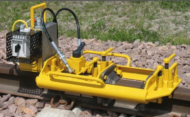
HYDRAULIC SHEARING UNITS TRANSLATION OF THE ORIGINAL OPERATION MANUAL

                                                                        Rev. 03/2021-02-03
                                                                               Page 2 of 22
HYDRAULIC SHEARING UNITS TRANSLATION OF THE ORIGINAL OPERATION MANUAL

1. General .................................................................................................................................... 5
      1.1     About this operation manual .............................................................................................................. 5
      1.2     Symbols in this operation manual ...................................................................................................... 5
      1.3     Using these operation manual ............................................................................................................ 5
      1.4     Product identification – type plate ..................................................................................................... 6
      1.5     About the shearing unit ...................................................................................................................... 6
      1.6     Applicable documents ........................................................................................................................ 6
      1.7     Liability................................................................................................................................................ 6
      1.8     Copyright ............................................................................................................................................ 6
      1.9     Warranty ............................................................................................................................................. 6

2. Notes for your safety ............................................................................................................... 7
      2.1     Intended use ....................................................................................................................................... 7
      2.2     Foreseeable misuse ............................................................................................................................ 7
      2.3     Other specifications ............................................................................................................................ 7
      2.4     General hazard sources ...................................................................................................................... 7

              2.4.1       Risk of injury in the work environment ................................................................................. 7
              2.4.2       Risk of injury during operation .............................................................................................. 8

      2.5     Safety signage ..................................................................................................................................... 9
      2.6     Conduct in the event of an emergency ............................................................................................... 9
      2.7     Operator duties .................................................................................................................................. 9
      2.8     Personnel qualification ..................................................................................................................... 10

              2.8.1       General ................................................................................................................................ 10
              2.8.2       Operating personnel (users) ................................................................................................ 10

      2.9     Personal protective equipment ........................................................................................................ 10

3. Hydraulic shearing unit, design and function ......................................................................... 11
      3.1     Functional description/operation ..................................................................................................... 11
      3.2     Hydraulic shearing unit components ................................................................................................ 11
      3.3     U-L series shearing device for flat-bottom, grooved and crane rails ................................................ 11

              3.3.1       U-L 4 series .......................................................................................................................... 12
              3.3.2       U-L S series .......................................................................................................................... 12
              3.3.3       U-L W series ......................................................................................................................... 13
              3.3.4       U-L RK series ........................................................................................................................ 13
              3.3.5       Shear blades ........................................................................................................................ 13
              3.3.6       Use of guide shoes, stop blocks, intermediate plates for the U-L RK series
                          shearing device .................................................................................................................... 14

      3.4     Power Units ...................................................................................................................................... 15

              3.4.1       General ................................................................................................................................ 15
              3.4.2       Power units, flange-mounted .............................................................................................. 16

                          3.4.2.1         Hand pump .......................................................................................................... 16

                          3.4.2.2         Hydraulic pump with electric motor, series L ...................................................... 17

                                                                                                                                                                            Rev. 03/2021-02-03
                                                                                                                                                                                   Page 3 of 22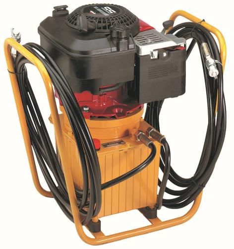
HYDRAULIC SHEARING UNITS TRANSLATION OF THE ORIGINAL OPERATION MANUAL

             3.4.3       Power units, separate .......................................................................................................... 17

                         3.4.3.1         Power units with electric motor or combustion engine ...................................... 17

                         3.4.3.2         Power units with petrol-driven engines .............................................................. 18

                         3.4.3.3         Power units with electric motors ........................................................................ 18

                         3.4.3.4         Battery-powered power unit ............................................................................... 19

     3.5     Hydraulic hoses ................................................................................................................................. 19

4. Commissioning the shearing unit ........................................................................................... 20
     4.1     Mounting the shear blades ............................................................................................................... 20
     4.2     Coupling the hoses ........................................................................................................................... 20
     4.3     Test run ............................................................................................................................................. 20
     4.4     Shearing process ............................................................................................................................... 21

5. Servicing and maintenance .................................................................................................... 22
     5.1     Shearing device ................................................................................................................................. 22
     5.2     Shear blades ..................................................................................................................................... 22
     5.3     Power Units ...................................................................................................................................... 22
     5.4     Hydraulic hoses, quick release connectors ....................................................................................... 22

6. Disposal/recycling .................................................................................................................. 22

Publisher:
ELEKTRO-THERMIT GMBH & CO. KG
A GOLDSCHMIDT COMPANY
Chemiestr. 24, 06132 Halle (Saale), Germany
Phone +49 345 7795-600, Fax +49 345 7795-770
et@goldschmidt.com, www.goldschmidt.com

Publication date: 2012-03-01
Status of documentation: 2021-02-03

Images: M. Nies, Agentur Format78 GmbH, Elektro-Thermit GmbH & Co. KG

                                                                                                                                                                         Rev. 03/2021-02-03
                                                                                                                                                                                Page 4 of 22
HYDRAULIC SHEARING UNITS TRANSLATION OF THE ORIGINAL OPERATION MANUAL

1.       General
1.1      About this operation manual

This operation manual contains all information for proper use of U-L series shearing devices including the available power units that
can be used with them. Amongst other things, it contains information regarding commissioning, operation, transportation and
troubleshooting of the devices.
At the moment, the U-L series covers the following types: U-L 4, U-L S, U-L W, U-L RK

Please note the following points:
• The operation manual is part of the shearing unit.
• The user must always have access to the operation manual.
• The operation manual must be kept near the shearing unit at all times throughout its entire service life.
• If sharing the shearing unit, it must also be given to other operators.

1.2      Symbols in this operation manual

Pay attention to the symbols employed when using this operation manual. Failure to comply with these can lead to the following:
• Risk of injury to staff,
• Damage to the shearing unit or the surrounding area,
• the loss of contractual warranty cover, or
• rejection of liability by the manufacturer.

This operation manual use the following symbols:

          SYMBOL              DEFINITION

                              WARNING designates a hazard with a moderate level of risk that, if not prevented, can lead to serious
         WARNING
                              injury.

            NOTE              Note, failure to observe this may give rise to an environmental incident or material damage.

                              Caution - risk of injury

                              General note with helpful tips and additional information.

                              Read the safety instructions before using the unit. Failure to do this may lead to injuries and to mate-
                              rial damage.

Signal words and symbols

1.3      Using these operation manual

             The information in this operation manual is binding in nature. Every user of the shearing unit must have read and un-
             derstood the whole of this operation manual before use. Always follow the instructions, prohibitions and commands
             and pay attention to all the safety notes contained.

                                                                                                                  Rev. 03/2021-02-03
                                                                                                                         Page 5 of 22
HYDRAULIC SHEARING UNITS TRANSLATION OF THE ORIGINAL OPERATION MANUAL

1.4       Product identification – type plate

Type plate (figure is similar)

1.5       About the shearing unit

The shearing unit consists of a shearing device and a power unit and is used to remove off the excess weld metal after carrying out
a Thermit® weld.

1.6       Applicable documents

The work instructions for the relevant Thermit® welding process are the applicable documents. They contain important information
about how to perform the welding procedure and the shearing process.

1.7       Liability

The user is liable if there is a failure to follow this operation manual. The warranty is rendered void if damage to the shearing unit
and its accessories, or for malfunctions, that arise from non-compliance with the operation manual of due to improper use on the
part of the user.

          Retrofits, amendments or use of other units that are not certified by the manufacturer are not covered by this warranty.
          The CE conformity that was issued also becomes void.

1.8       Copyright

This operation manual are protected by Elektro-Thermit GmbH & Co. KG copyright. Reproduction of the document either wholly or
in part and/or dissemination to third parties requires the prior written consent of Elektro-Thermit GmbH & Co. KG.

1.9       Warranty

The legally stipulated obligation governing the warranty period applies.
Elektro-Thermit GmbH & Co. KG does not accept any responsibility and provides no warranty cover and shall absolve itself of any
claims to third parties in the event of personal injury or material damage etc. arising for one or more of the following reasons
caused by the operator or by a third party:
• Improper use of the shearing unit,
• Failure to observe the notes in this operation manual;
• Failure to comply with the specified application limits and operating conditions;
• improper commissioning, operation, inspection and/or maintenance of the shearing unit;
• The use of inappropriate accessories or of non-approved spare parts.

                                                                                                                   Rev. 03/2021-02-03
                                                                                                                          Page 6 of 22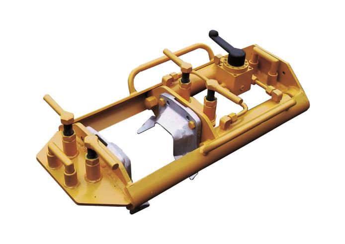
HYDRAULIC SHEARING UNITS TRANSLATION OF THE ORIGINAL OPERATION MANUAL

2.        Notes for your safety

This chapter contains all the information relating to safety.

              Before using the shearing unit, read this chapter thoroughly and pay attention to the notes when using the product.

2.1       Intended use

The shearing unit consists of a U-L series shearing device and a power unit with accessories coupled to it in accordance with the
selection guide. It is used for the purpose set out in point 1.5.

          In case of personal injury or damage to property resulting from improper use of the shearing unit, Elektro-Thermit GmbH
          & Co. KG cannot accept liability.

2.2       Foreseeable misuse

Foreseeable misuse is when the shearing unit is used for a purpose other than the one described.

2.3       Other specifications

In addition to the details in this operation manual, compliance with the legislative stipulations governing accident prevention and
environmental protection as well as the health & safety at work specifications of the operator is mandatory.
The operator is considered to be whoever is using the shearing unit or allows it to be used by suitable, trained staff.
The safety specifications issued by railway authorities for work on the track and near the track must be followed. No such work can
commence until the responsible safety officers have issued their approval.

2.4       General hazard sources

      The safety precautions stated below must be observed! The safety instructions draw attention to hazards with the potential
      to cause personal injury and/or damage to equipment and to the environment and are intended to prevent or avert these
      hazards.

2.4.1 Risk of injury in the work environment

Welding and shearing work both take place in a work environment on a construction site, in which several cases of welding and
other work may be carried out in close proximity at the same time. Amongst other things, there is an increased risk of injury due to:
• Railway traffic on adjacent rails,
• Being run over by construction vehicles,
• Being caught on construction vehicles and other moving work machines,
• Slipping on smooth, wet or oily surfaces,
• Stumbling over obstacles,
• Falling onto pointed and angular objects,
• Burns on hot surfaces.

                                                                                                                 Rev. 03/2021-02-03
                                                                                                                        Page 7 of 22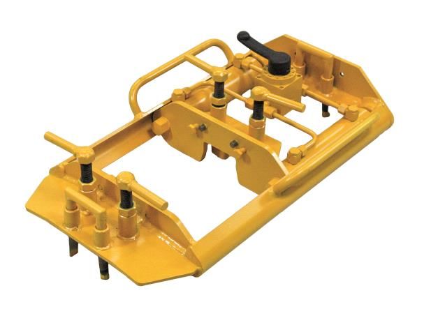
HYDRAULIC SHEARING UNITS TRANSLATION OF THE ORIGINAL OPERATION MANUAL

Follow the precautionary measures below:
• Observe all regulations on the construction site.
• Ensure that no other people are present within the range of the shearing unit.
• Only use if lighting is sufficient.
• Be careful and alert at all times.
• Ensure that there is adequate ventilation.
• If the drive unit is running, do not leave it unsupervised.

2.4.2 Risk of injury during operation

The shearing unit must only be used by trained staff. Improper use may result in serious injuries such as burns or crushing.

Follow the precautionary measures below:
• Ensure that the construction site cannot be accessed by unauthorized people. Coordination must be carried out by construction
   site management.
• The shearing unit must be protected against unauthorized use.
• Transportation, set-up and lifting of the shearing device must be done by two people. Pay attention to the weight of the unit!
• Always ensure that no readily flammable or explosive substances are located close to the shearing unit.
• Where necessary, clear the workplace of combustible substances and provide sufficient ventilation.
• Before use, check the shearing device to see if there are any leaks, and do not use if there are any!
• Wear personal protective equipment (see Chapter 2.9 "Personal protective equipment").
• Ensure that there is no risk of electric shock.
• Do not put the shearing unit in water or hose it down.
• Lay out the hydraulic hoses to avoid tripping.

                                                                                                             Rev. 03/2021-02-03
                                                                                                                    Page 8 of 22
HYDRAULIC SHEARING UNITS TRANSLATION OF THE ORIGINAL OPERATION MANUAL

2.5       Safety signage

   NOTE

   Keep safety designations readable at all times! In the event of safety signage getting damaged or going missing during the ser-
   vice life of the unit, the operator must obtain suitable replacements.

      SYMBOL          DEFINITION                                       SYMBOL          DEFINITION

                      Follow operation manual                                          Wear safety gloves

                      Wear eye protection                                              Wear protective clothing

                      Wear safety footwear

                      Warning of hot surfaces                                          Risk of crushing injuries

Safety signage

2.6       Conduct in the event of an emergency

If an emergency occurs, then immediately stop shearing by putting the control valve on the shearing device into the BACK position
to open the shearing traverse and to start the return, then switch off the power unit and leave the hazardous area as quickly as
possible.
      •   In the event of personal injury, immediately initiate first aid measures.
      •   In the event of a fire, immediately initiate the requisite steps to combat the fire.

2.7       Operator duties

The system operator is the person who operates the shearing unit for vocational or business purposes, or who who arranges for a
third party to use/apply the machine, and who assumes during all operations the legal product responsibility for the protection of
the machine operator, in-house personnel or third parties.

Obligations of the system operator:
The operator must know and implement the applicable specifications governing workplace safety and accident prevention.

                                                                                                                   Rev. 03/2021-02-03
                                                                                                                          Page 9 of 22
HYDRAULIC SHEARING UNITS TRANSLATION OF THE ORIGINAL OPERATION MANUAL
2.8 Personnel qualification
2.8.1 General
Work must only be carried out by qualified staff!
All persons who satisfy the following requirements are entitled to work with the shearing unit.
• You have read and understood the whole of this operation manual.
• To assure workplace safety, you wear the required personal protective equipment (see chapter 2.9 "Personal protective equip-
ment").
• You always pay attention to the health & safety at work stipulations for the operator as well as to all legislative provisions of
relevance to personal safety and to the safety of other persons.
2.8.2 Operating personnel (users)
Operating staff on the shearing unit that carry out work as described in this operation manual, are defined as follows:
• All personnel must be trained on a continuous basis about technological innovations and must have the requisite basic under-
standing of how to use U-L series shearing devices and its power units along with the accessories.
• The following main points should be covered as part of initial instruction:
• Functional description of the shearing unit,
• Explanation of the individual components,
• Explanation of the danger sources,
• Use of the shearing unit,
• Detection of functional defects and problems.
2.9 Personal protective equipment
If the system operator does not issue additional stipulations, the personal protective equipment listed in the following table must
be used with the shearing unit.
SYMBOL PROTECTIVE EQUIPMENT TASKS
Protective workplace clothing Transportation, commissioning, op-
(Welder's protective clothing as per EN 470-1, high-visibility clothing eration, decommissioning, mainte-
as per EN 471) nance, cleaning/upkeep
Transportation, commissioning, op-
Safety footwear
eration, decommissioning, mainte-
(Safety shoe S3 as per EN ISO 20345 for ankle-high shoes)
nance, cleaning/upkeep
Safety goggles Operation (shearing)
Workplace gloves
(severe mechanical hazards in accordance with EN 388 (4242), EN Transportation, commissioning, op-
402, eration, decommissioning, mainte-
if necessary, gloves that protect against thermal hazards as per EN nance, cleaning/upkeep
407)
Personal protective equipment
Rev. 03/2021-02-03
Page 10 of 22HYDRAULIC SHEARING UNITS TRANSLATION OF THE ORIGINAL OPERATION MANUAL
3. Hydraulic shearing unit, design and function
3.1 Functional description/operation
The shearing unit consists of a shearing device and a power unit and is used to remove off the excess weld metal after carrying out
of Thermit® welding.
The shearing unit consists of a U-L 4 series shearing device and a series L power unit.
3.2 Hydraulic shearing unit components
The hydraulic shearing unit consists of three components.
Shearing device
It consists of a guide frame, 2 hydraulic cylinders, a shearing traverse, 4 guide shoes and a 4/3 control valve.
Power unit
This can be operated manually, electrically, or with petrol.
Hydraulic hoses
These connect the shearing device with the power unit.
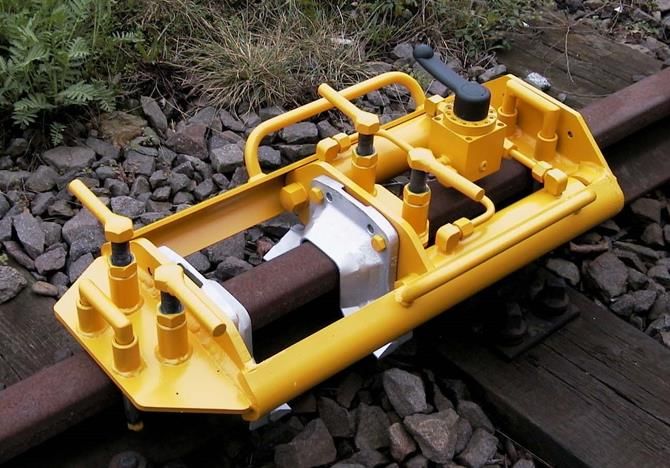
3.3 U-L series shearing device for flat-bottom, grooved and crane rails
The shearing device is fitted with two the rail profile adapted, exchangeable shear blades (1) that are moved on top of each other
by two hydraulic cylinders (2) arranged in parallel, enabling excess weld metal to be shorn off on both sides. Controlling takes place
via a 4/3 control valve.
(1) Shear blade
(2) Hydraulic cylinder
2
(3) Guide shoe
4
(4) 4/3 control valve
1
3
Rev. 03/2021-02-03
Page 11 of 22HYDRAULIC SHEARING UNITS TRANSLATION OF THE ORIGINAL OPERATION MANUAL
COMPRESSIVE
SERIES STROKE WEIGHT SHEAR BLADES RAIL WIDE GAP
FORCE
(KN) (MM) (KG) TYPE TYPE L 50, L 75
U-L 4 200 150 33.5 A, B Flat-bottom +
U-L S 200 150 28.5 A, B Flat-bottom -
U-L W 200 150 37.5 A, B Flat-bottom +
Flat-bottom,
U-L RK 200 150 39.0 A, B, C +
groove, crane
Overview of shearing devices
3.3.1 U-L 4 series
The shearing device with power unit works on the pincer principle to take excess weld metal away from flat bottom rails. Type A
and B shear blades can be used.
3.3.2 U-L S series
This unit corresponds to the U-L 4 series, but has a narrower frame and is preferably used in switch areas. It is not possible to shear
welds with wide gaps. Type A and B shear blades can be used.
Rev. 03/2021-02-03
Page 12 of 22HYDRAULIC SHEARING UNITS TRANSLATION OF THE ORIGINAL OPERATION MANUAL
3.3.3 U-L W series
This unit corresponds to the U-L 4 series, but has a wider frame. This is a special version. Type A and B shear blades can be used.
3.3.4 U-L RK series
This unit has a wide frame and a guide shoes that can be flexibly used. It can be used on flat-bottom, grooved and crane rails. Type
A, B and C shear blades can be used.
3.3.5 Shear blades
The relevant shear blade types are adapted to the rail profile. Their cutting edges consist of hard-wearing, heat-resistant steel.
It is extremely important that the shearing times stated in the operation manual are observed! Shearing a cold weld leads
to the destruction of the cutters on the shear blades.
Type A flat-bottom rail Type B flat-bottom and crane rail Type C grooved rail
The type of shear blade and rail profile must be stated when ordering.
Rev. 03/2021-02-03
Page 13 of 22HYDRAULIC SHEARING UNITS TRANSLATION OF THE ORIGINAL OPERATION MANUAL
3.3.6 Use of guide shoes, stop blocks, intermediate plates for the U-L RK series shearing device
Depending on the rail profile, various guide shoes can be used in combination with stop blocks, distance plates and intermediate
plates.
PROFILES 2 4 4 2
GUIDE SHOES STOP BLOCKS DISTANCE PLATES INTERMEDIATE PLATES
PASSAGE WIDTH
TYPE – MASS L1 / MASS TYPE TYPE
L2
59R1, 60R1 Type R – 140/40 - - 155
67R1 Type Ph 37a - - 155
57R1 Type R – 140/40 - - 155
62R1 Type R – 140/40 - - 155
NP 4 Type R – 140/40 - - 155
75C1 Type R – 140/40 - - 155
105Cr1 Type VK (2A) – 140/90 - - 155
A120, MRS 125 Type VK (2A) – 140/90 - - 155
A100, PRI 85R, 175 CR Type VK (1A) – 120/70 Type 1A (10 mm) - 155
A 75 Type VK (2B) – 100/50 Type 2B (20 mm) 10 mm 85
A 65 Type VK (2B) – 100/50 Type 2B (20 mm) 10 mm 85
A 55 Type VK (1B) – 80/30 Type 1B (30 mm) 2x10 mm 85
A 45 Type VK (1B) – 80/30 Type 1B (30 mm) 2x10 mm 85
R 65 Type VK (1B) – 80/30 Type 1B (30 mm) 2x10 mm 85
60E1 Type VK (1B) – 80/30 Type 1B (30 mm) 2x10 mm 85
54E1 Type VK (1B) – 80/30 Type 1B (30 mm) 2x10 mm 85
54E3 Type VK (1B) – 80/30 Type 1B (30 mm) 2x10 mm 85
49E1 Type VK (1B) – 80/30 Type 1B (30 mm) 2x10 mm 85
Further profiles on request.
Rev. 03/2021-02-03
Page 14 of 22HYDRAULIC SHEARING UNITS TRANSLATION OF THE ORIGINAL OPERATION MANUAL
3.4 Power Units
3.4.1 General
Depending on the design, these units can either be flange-mounted on the shearing device or be used as individual components.
CONVEYING MOUNTED/ FUEL CAPACITY SOUND PRESSURE
TYPE WEIGHT
CAPACITY SEPARATE CAPACITY HYDRAULIC OIL LEVEL
Operator-
Hand pump +/- 10.8 kg 0.7 l
dependent
Series L,
Alternating current
0.85 l/min +/- 19.6 kg 2.5 l 73 db
motor
(0.55 kW, 230 V)
Alternating current
-/+ 78 db (1500 rpm)
motor 1.8 l/min 38 kg 2.5 l
82 db (3000 rpm)
(1.5 kW, 230 V)
Three-phase current
-/+ 78 db (1500 rpm)
motor 1.8 l/min 34 kg 2.5 l
82 db (3000 rpm)
(1.5 kW, 230/380 V)
4-stroke motor
-/+ 70 db (1500 rpm)
(3 kW) 1.8 l/min 31 kg 4l 2.5 l
83 db (3000 rpm)
Briggs & Stratton
4-stroke motor
-/+ 70 db (1500 rpm)
(3 kW) 1.8 l/min 34 kg 4l 2.5 l
83 db (3000 rpm)
Honda
MPU 410 B,
Direct current, -/+
1.3 l/min 26.5 kg 3.8 l 68 db
battery
(1.4 kW, 60 V)
Overview of power units
Hydraulic oil with a viscosity of 15 – 25 cSt (40°C) as per ISO VG 22 should be used.
Always check the oil level prior to commissioning! Only use the shearing device when connected to the power unit.
Pump connections for all power units:
Pressure hose: P – P, Return hose: T -T
WARNING
The oil pressure generated by the hydraulic pump is set to 500 bar at the factory via a pressure relief valve.
This must not be changed by the operator!
Rev. 03/2021-02-03
Page 15 of 22HYDRAULIC SHEARING UNITS TRANSLATION OF THE ORIGINAL OPERATION MANUAL
NOTE
The shearing unit must only be operated by a single person, never with two!
Ensure that the shearing unit is in ideal condition before every use!
Ventilation
The union nut on the pressure hose on the power unit should be briefly loosened (not unscrewed), then start the motor. Observe
the union nut, a mixture of oil and air escapes after a few seconds. When an even flow of oil seeps out, tighten the union nut once
again. Carry out 3-4 test runs when the motor is running. Immediately catch any escaping oil and remove it.
Afterwards, check the oil level of the container with the dipstick.
3.4.2 Power units, flange-mounted
3.4.2.1 Hand pump
Actuation of the double-piston hand pump is with a hand-operated double stroke lever.
1 2
To shear, the extension (1) must be fitted on the stationary hand-operated lever (2) and this must be quickly moved back and forth.
Approx. 25 to 30 double strokes are necessary depending on the welding process. Afterwards, it is advised to move it back quickly
without the extension to protect the cutting edges.
The hand pump can also be connected with quick release connectors and hydraulic hoses so that it can be disconnected and that
alternative power units listed in the overview can also be connected.
Rev. 03/2021-02-03
Page 16 of 22HYDRAULIC SHEARING UNITS TRANSLATION OF THE ORIGINAL OPERATION MANUAL
3.4.2.2 Hydraulic pump with electric motor, series L
The unit, consisting of a hydraulic pump with electric motor.
3.4.3 Power units, separate
Motorised drives are available as separate power units. The hydraulic pump integrated in an oil tank with a support frame may, as
an option, be equipped with different motors. See the following chapter.
The motor's technical data can be found in the manufacturer's operation manual.
Fill with hydraulic oil and petrol if necessary before initial commissioning!
3.4.3.1 Power units with electric motor or combustion engine
NOTE
Follow the manufacturer's operation manual!
Short-term operation with max. operating pressure of up to 500 bar, and up to 350 bar for non-stop operation.
Accessories
The following accessories are part of the scope of delivery for every power unit:
• Hydraulic oil as per ISO VG 22
• Hopper
Rev. 03/2021-02-03
Page 17 of 22HYDRAULIC SHEARING UNITS TRANSLATION OF THE ORIGINAL OPERATION MANUAL
3.4.3.2 Power units with petrol-driven engines
4-stroke engines from Briggs & Stratton and Honda are available
4-stroke engine "Briggs & Stratton" 4-stroke engine "Honda"
3.4.3.3 Power units with electric motors
A three-phase and an alternating current motor are available, as well as a battery-driven motor. The three-phase and alternating
current motors are supplied with a 15 m connecting cable and a motor protection switch as per the IEC – 204 standard along with a
double insulated protective housing in the IP 54 protective class.
Rev. 03/2021-02-03
Page 18 of 22HYDRAULIC SHEARING UNITS TRANSLATION OF THE ORIGINAL OPERATION MANUAL
3.4.3.4 Battery-powered power unit
The MPU 410 B battery-powered power unit is available as a compact, emissions-free drive.
3.5 Hydraulic hoses
Connection of the power unit with the shearing device is done with hydraulic hoses as per EN ISO 3821.
Three variants are used.
Hose pair 0.6 m
In the case of flange-mounted power units, hoses can either be connected in a fixed manner or are connected with quick release
connector to the junction with the control valve. The shearing device can then either be operated with a flange-mounted hand
pump or with the series L power unit.
Hose pair 7 m with quick release connector on one side
Two securely mounted hoses should be used if a separate power unit is to be used. The connection to the shearing device is via
quick release connector (except for battery-driven power units).
Hose pair 7 m with quick release connector on both sides
The battery-driven power unit is operated with a pair of hoses with quick release couplings on both sides.
WARNING
Do not mix up the connections!
Couplings must be fully locked in position! Only use permitted hoses!
Check hoses in line with legal requirements!
Rev. 03/2021-02-03
Page 19 of 22HYDRAULIC SHEARING UNITS TRANSLATION OF THE ORIGINAL OPERATION MANUAL
4. Commissioning the shearing unit
4.1 Mounting the shear blades
The shear blades should be positioned and screwed into place via the positioning pins on the traverses of the shearing device. In
this case, use only the shear blades that are appropriate for the relevant rail profile.
4.2 Coupling the hoses
Coupling is not necessary on the version with a flange-mounted power unit. If the power unit is separate then coupling to the
shearing device takes place as follows:
Coupling the pressure and return side
1. Remove the cap from the coupling connector and coupling
sleeve
2. Push the coupling connector into the coupling sleeve, then
push back the knurled ring on the sleeve.
3. After decoupling push the caps back on again to protect
the hoses and valve connections from dirt and damage.
4.3 Test run
The shearing unit should have a test run and the oil level must be checked before starting welding.
In this case, proceed as follows:
1. Couple the hoses to the shearing device.
2. Place the shearing device on the rail.
3. Using the nut, set the guide shoes to approx. 1 mm below the rail head.
4. Set the control valve on the pressure unit to IDLE SPEED.
5. Switch on the power unit.
6. Set control valve to FORWARDS and the shear blades come together. Leave it in the end position for approx. 1 second, motor
noise level increases.
7. Slowly change the setting on the control valve from IDLE SPEED to BACK. Allow the piston to move to the end position. Slowly
change the setting on the control valve to IDLE SPEED again.
IDLE SPEED FORWARDS BACKWARDS
Valve positions
Rev. 03/2021-02-03
Page 20 of 22HYDRAULIC SHEARING UNITS TRANSLATION OF THE ORIGINAL OPERATION MANUAL
4.4 Shearing process
1 2
1. Turn the guide shoes in the transport position (1) 3. Turn the hold guide shoes in the operating position (2)
2. With two people, place the shearing device on the rail.
4. Switch on the power unit or use the hand pump to start shearing.
5. Start the shearing process by moving the control valve to FORWARDS, the shear blades come together.
6. Slowly move the control valve to BACKWARDS via IDLE SPEED, the shear blades move away from each other into the starting
position, then slowly move the control valve back to IDLE SPEED.
7. To lift the guide shoes, turn to the transport position (1).
8. Lift and shut down the shearing device with two people.
9. If necessary, strike off sheared excess weld metal with the hammer.
If the power unit malfunctions during shearing then the shearing device can be lifted as follows:
• Release the guide shoes, transport position (1),
• Control valve in BACKWARDS,
• Push the shear blades as far apart as required with a crow bar until the shearing device can be lifted.
Rev. 03/2021-02-03
Page 21 of 22HYDRAULIC SHEARING UNITS TRANSLATION OF THE ORIGINAL OPERATION MANUAL
5. Servicing and maintenance
5.1 Shearing device
• Keep contact surfaces for shear blades and inner surfaces for the support frame clean.
• Visual inspection for leak tightness – oil leakage due to the piping, coupling, control valve and cylinder.
• Visual inspection of the frame and weld seams for cracks and other damage.
5.2 Shear blades
Elimination of burrs
Small burrs may form on the inside of the cutting surfaces, and these should be immediately and carefully removed with an angle
grinder.
Elimination of displacements
Small displacements may form on the inside of the cutting surfaces, and these should be carefully removed with an angle grinder.
To do so, bring the shear blades together.
Regrinding
Only process these ex-
If the outer area of the cutting edge is heavily worn, then this must be reground. To do so,
ternal bevels.
disassemble the shear blades.
When bringing them together the cutting edges should come together along the entire
length of the cutting edges.
Replacing the shear blades
If reworking is not possible, then the shear blades must be replaced.
5.3 Power Units
Power units should be maintained in line with the manufacturer's instructions.
5.4 Hydraulic hoses, quick release connectors
• The coupling halves should be cleaned regularly and carefully.
• The coupling halves and their cover caps should be checked regularly for damage, functionality and to see if they fit properly.
• Use cover caps on the coupling halves when not in use.
• Check the cover on hoses for leak tightness and damage.
• Hoses should be properly reeled in for storage.
6. Disposal/recycling
Ensure that all components of the shearing unit are disposed of in an environmentally friendly manner.
At the end of the service life of the shearing unit, the owner must arrange for disposal of the machine in accordance with prevailing
specifications.
Rev. 03/2021-02-03
Page 22 of 22You can also read


