Fabrication and Characterization of Nanostructured Mesoporous Ni(OH)2 Electrode Using Pluronic P84 PEO/PPO/PEO Triblock CopolymerTemplate ...
←
→
Page content transcription
If your browser does not render page correctly, please read the page content below
Int. J. Electrochem. Sci., 16 (2021) Article ID: 210827, doi: 10.20964/2021.08.32

                                                                         International Journal of
                                                                         ELECTROCHEMICAL
                                                                                 SCIENCE
                                                                                www.electrochemsci.org

Fabrication and Characterization of Nanostructured
Mesoporous Ni(OH)2 Electrode Using Pluronic P84
PEO/PPO/PEO Triblock CopolymerTemplate
A.A. Al-Owais1, I. S El-Hallag2,*
1
  Chemistry Department, Faculty of Science, King Saud University, Reyad, Sa
2
  Department of Chemistry, Faculty of Science, Tanta University, Tanta, Egypt t
*
 E-mail: i.elhallag@yahoo.com

Received: 31 March 2021 / Accepted: 22 May 2021 / Published: 30 June 2021

Block, copolymer of polyethylene oxide/ polypropylene oxide/ polyethylene oxide (PEO/PPE/PEO)
(Pluronic P84) are utilized as template for constructing electrode with high surface area. This electrode
is of much interest for many applications including electrochemical detectors, batteries, and fuel cells.
Pluronic P84 are example of a triblock copolymer to template the electrodeposition of a mesoporous
nickel film. This method is found to give a high increase in surface area. TEM and XRD of Pluronic P84
templated nickel on gold surfaces shows a peak consistent with a pore to pore spacing of 9.5 nm.
Electrochemical inspection of the deposited film using cyclic voltammetric exhibits that the
nanostructured have high surface area and a pore structure that allows extremely fast diffusion of species
to active sites within the structure.

Keywords: mesoporous; nanostructured; pluronic P84; x-ray diffraction.

1. INTRODUCTION

         The synthesis of nanostructured porous electrode using self-assembling surfactants and polym-
ers as templates producing high surface area with good characteristics. This idea pioneered by Beck et
al. [1] to make up mesoporous silica containing arranged arrays of pores with internal radius of 1–2.5
nm and configuration of a narrow pore size. Attard et al, indicated that the utilize of such a method for
fabrication of a porous platinum layer on planar electrodes [2]. This method was extended to other metals
such as Sn [3, 4], Co [5], and Ni [6]. Here, we are intended to conducting such methods to fabricate
arranged nanostructured porous electrode with high surface area. The structure of the nanostructured
mesoporous metal films has been concerned to cylindrical pores ordered as hexagonal arrays. Triblock
copolymers of the Pluronic family exhibit a very large range of framework depending upon temperature,
Int. J. Electrochem. Sci., 16 (2021) Article ID: 210827 2
and constituents. Further, the phase diagrams have been extensively investigated [7, 8], and so can give
a starting point for determining the constituents and temperature which might produce a particular
nanostructured. Such copolymers have been reported previously for working well in the templating of
porous silica [9].
To the best of our knowledge, there is no work reported for fabricate nanostructured mesoporous
Ni film using block, copolymers of polyethylene oxide/ polypropylene oxide/ polyethylene oxide
(PEO/PPE/PEO) (pluronic P84). In this article, a simple method for electrodeposition of ordered meso-
pore hexagonal electrodeposited Ni(OH)2 “H1-e Ni (OH)2” films from the hexagonal template of
pluronic 84 was described. The properties of capacitive of the H1-e Ni(OH)2 hydroxide thin films were
examined via cyclic voltammetry method. The influence of potential sweep rates on the capacitance
properties of H1–e Ni (OH)2 films were analyzed for performing optimum conditions for deposited H1–
e Ni (OH)2 film with the best capacitive characteristics.
2. EXPERIMENTAL
2.1 Materials and solutions
All chemicals were very pure and used as supplied. Nickel acetate (NiAc2.4H2O 99.5%),
potassium acetate (KAc 99%) and P-xylene (99%) were supplied from Fluka. Plouronic 84 is a
polyethylene oxide/ polypropylene oxide/ polyethylene oxide (PEO/PPE/PEO) copolymer. Pluronic P84
non –ionic surfactant [(EO)19(PO)43(EO)], aqueous solution of NiAc2.4H2O, KAc and p-xylene are
utilized as a mixture for plating process. The fabricated hexagonal phase (Hl) of plating bath consists of
53.13 wt% aqueous Ni acetate & K acetate, 44.6% weight of pluronic P84 and 2.23% weight of p-
xylene which remain stable at room temperature for more than a four weeks.
2.2 Instrumentation
The apparatus used for electrochemical deposition and cyclic voltammetry (CV) measurements
are Potentiostat EG & G 283 and a three electrode cell (15 cm3 volume space).
2.3 Electrodeposition process
The H1-e Ni(OH)2 films were electrodeposited in a three-electrode cell at ambient temperature.
The radius of gold electrode was a 0.5 mm, while for the morphology investigation of, the working
electrode was flat gold substrate with geometrical surface area 100 mm 2. Platinum gauze with area 100
mm2 was used as auxiliary electrode and saturated calomel electrode (SCE) as the standard electrode.
The cleaning process of gold disk electrode was carried out by polishing paper with grade 1200 followed
by alumina powder of two grades: 1.0 and 0.3 μm then rinsed with very pure water. The plating mixture
described previously was used as electrolyte, at constant potential equal -0.91 V vs. SCE for achievement
the electrochemical experiments for deposition process. The deposition of Ni(OH)2 film was performedInt. J. Electrochem. Sci., 16 (2021) Article ID: 210827 3
by passing the charge for definite time in the electrochemical cell. After deposition, the electrodes were
cleaned with too much amounts of very pure water to get rid of the surfactant.
2.4 Cyclic voltammetry characterization
The Ni(OH)2 film was electrodeposited on disk gold electrode and characterized via cyclic
voltammetry at various scan rates (v) and at ambient temperature.
2.5 X-ray diffraction characterization
Bruker D8 x-ray diffractometer using Cu Kα radiation (λ = 0.154 nm) was used XRD with Cu
Kα radiation to confirm the formation of a nanostructured mesoporous film and for the measurement the
diameter of electrodeposited Hl-e Ni(OH)2 films.
2.6 TEM measurements
The ordered and homogeneity of the mesoporous structure was achieved using JEOL 2000FX
transmission electron microscope (TEM) operating at an accelerating voltage of 200 KV.
2.7 SEM characterization
The scanning electron microscope (SEM) (JEOL 6400) was applied to look at the morphology
and thickness of the electrodeposited nickel hydroxide films.
2.8. Convolutive voltammetry
Convolution-deconvolution voltammetry were achieved using EG & G condecon software
program. It was used to examine the nature of electrode reaction and determining the some
electrochemical and chemical parameters such as diffusion coefficient (D), standard redox potential
(Eo ) and homogeneous chemical rate constant (kc).
2.9 Digital simulation
Condesim EG & G package was used for performing the simulation process. Simulation method
aim to confirm the electrochemical and chemical parameters calculated from experimental cyclic
voltammograms.
3. RESULTS AND DISCUSSION
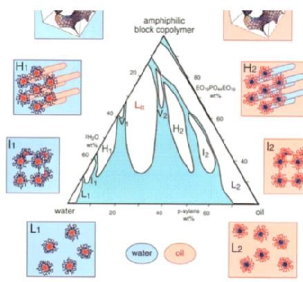
Here in this work, pluronic 84 (P84) has been employed as the surfactant. When mixed with the
aqueous solution of the metal salt, the hydrophobic blocks cluster together and the hydrophilic blocksInt. J. Electrochem. Sci., 16 (2021) Article ID: 210827 4
dissolve in the water, producing the lyotropic liquid crystal phases. The most attractive phase of this
article is the hexagonal phase (HI) where the surfactant molecules aggregate into parallel cylindrical
rods arranged in a hexagonal pattern (Figure 1). The central of the surfactant rod is hydrophobic while
the aqueous species exist in the inter-distance between singleton rods [10]. The deposited H1-e Ni(OH)2
films were investigated utilizing cyclic voltammetry, scanning electron microscopy (SEM), transmission
electron microscopy (TEM), x-ray diffraction (XRD), convolutive voltammetry and digital simulation.
Figure 1 A. Phase diagram of Pluronic® P84 (PEO/PPO/PEO) in water and p-xylene at 25 °C. l1, H1,
V1, Lα, V2, H2 and l2 indicate normal micellar cubic, normal hexagonal, normal bicontinuous
cubic, lamellar, reverse bicontinuous cubic, reverse hexagonal and reverse micellar phases,
consequently.Int. J. Electrochem. Sci., 16 (2021) Article ID: 210827 5
Electrochemical
reduction of metal
ions.
.
Liquid crystal templates Nanostructured mesoporous
with metal. thin metal film on the gold
Figure 1B. The growth stages of the mesoporous hexagonal (H1-e Ni(OH)2) films electrodeposited in
the existence of a hexagonal liquid crystal template
3.1. Cyclic voltammetry characterization
0.00006
0.00004
0.00002
-1
0.2 V.s
i/A
-1
0.00000 0.1 V.s
-1
0.05 V.s
-1
0.02 V.s
-0.00002
-0.00004
-0.00006
0.0 0.2 0.4 0.6 0.8 1.0
E/ vs. SCE
Figure 2. Cyclic voltammograms of deposit H1-e Ni(OH)2 film from pluronic P84 in 0.1M KOH at
different sweep rates.
In this work the H1-e Ni(OH)2 electrode were used as supercapacitors and their achievement
was tested using cyclic sweep voltammetry. Figure 2 indicates that the CV curves of the HI–e Ni(OH)2
film electrode at different sweep rates. The shape of the CV waves exhibits that the capacitance
properties of H1-e Ni(OH)2 is distinct from that of the electric double-layer capacitance, which would
give a CV wave adjoining to an ideal rectangular shape. Also, the shape of the CV waves for the HI –
eNi(OH)2 plate is not quite affected by variation the sweep rates. This can be ascribed to the enhanced
mass transportation and electron transfer within the material due to its systematically ordered
mesoporous. The voltammetric waves shown in figure 2 indicate that the current peaks are directly
proportional to the sweep rate, revealing ideally capacitive nature [11]. It can also be seen that when the
scan rate grow, the peak current grows rapidly and the distance between the reductive and oxidative
waves becomes wider, which is mostly due to the polarization of the cell under high sweep rate. It isInt. J. Electrochem. Sci., 16 (2021) Article ID: 210827 6
well established that the anodic and cathodic waves are entitled to the oxidation of Ni(OH)2 to NiOOH
and the reverse process, respectively. The specific capacitance (C) of the deposited films can be
determined in accordance with the upcoming equation [12-14]:
C = Q / m v ΔV
Where Q is the half of the area of the CV waves and the symbols have their usual meaning. The
numerical values of specific capacitance calculated from the cyclic voltammetry experiments were listed
in Table 1.The effects of potential sweep rates on the capacitive properties of electrodeposited films are
indicated in Figure 3. The decrease in the value of capacitance with increasing the sweep rate arises from
the presence of inner active sites, which cannot precede the redox transitions completely at higher scan
rates of cyclic voltammograms [15].
1000
900
Specific Capacitance (F/g)
800
700
600
500
400
0 100 200 300 400 500
-1
v (V.s )
Figure 3. Specific capacitance of electrodeposited mesoporous nickel hydroxide films at different
sweep rates.
Table 1. Values of specific capacitance of electrodeposited mesoporous nickel hydroxide films at
different sweep rates.
Sweep rate (mVs-1 Specific capacitance
(F g-1)
10 980
20 870
50 715
100 630
200 513
500 440
The specific capacitance obtained at the slowest scan rate is believed to be close to that of full
utilization of the electrode material [15]. The lower sweep rates permit greater time for the proton to
enter the main mass of the nanostructured materialness. Such large values of capacitance are attributed
to the typical morphology and amorphous nature of the film [15].
Figure 4 displays the CV scan of the electrodeposited Ni(OH)2 films with and without template.
The templated film exhibited approximately fourfold increase in surface area over that without templateInt. J. Electrochem. Sci., 16 (2021) Article ID: 210827 7
(blank). Accordingly, the electrodeposited film contained some surface roughness inherent to
electrodeposition that increased the actual surface area of the nickel electrode surface in case of the
absence of template.
0.00006
0.00004
0.00002
i/A
0.00000
Templated Ni(OH)2 Electrode
-0.00002 Plain Ni Electrode
-0.00004
-0.00006
0.0 0.2 0.4 0.6 0.8 1.0
E/ vs. SCE
Figure 4. Cyclic voltammograms of plan Ni electrode and electrodeposited HI-eNi(OH)2 film in 0.1M
KOH
3.2. X-ray characterization
Figure 5A describe the low – angle XRD patterns of the “pluronic P84” template (curve a) and
the deposited H1-e Ni(OH)2 film (curve b), separately. Both curves indicate peaks at small angles, which
clarify the presence of a size – controlled nanoporosity. The hexagonal template displays a clear
diffraction peak with d – spacing of 9.2 nm at approximately 2Ө = 1.12° (curve a), which can be ordered
as the (100) plane.
100
intensity (a.u)
50
0
45 60 75
2 theta
(A)Int. J. Electrochem. Sci., 16 (2021) Article ID: 210827 8
100
intensity (a.u)
50
0
45 60 75
2 theta
(B)
Figure 5. (A) Low –angle XRD for the H1-Ni(OH)2 from pluronic P84 (a), for electrodeposited H1-
eNi(OH)2 film on gold substrate (b) and (B) wide – angle XRD for electrodeposited H1-eNi(OH)2
film on a gold substrate.
The pore to pore distance for this hexagonal arrangement, given by d100/ cos 30, is 9.2 nm. The
HI – e Ni(OH)2 film also indicates well defined peak at around 2Ө = 1.13 (curve b), which
corresponding to a d – spacing of 9.04 nm and a pore to pore distance of 9.25 nm, implying a porous
nanostructured extracted from the structure of the template electrolyte. As shown all the peaks are in
accordance with the conventions of Ni(OH)2. The XRD convention consists of the sharp peak at 45°,
except the substrate peaks, the XRD result corresponds to the well-known layered of Ni(OH)2 [16].
From the phase diagram composition we would anticipate to produce arrays of hexagonally
ordered pores. The combination of arranged structures indicated by the peaks in the XRD and the surface
area increase observed in the CV does not lend itself confirm that electrodeposition into the P84 lyotropic
liquid crystal template has given a hexagonal array of pores. The presence of only one peak in the XRD,
as has generally been observed in surfactant templated systems, does not indicate hexagonal pore
arrangement to be distinguished from cubic or lamellar assembly. Although we consider it greatly likely
that the polymer templated coating does consist of arrays of hexagonally arranged pores, it will need
TEM to establish this definitively.
3.3. SEM and TEM characterization of HI-e Ni hydroxide films
The scanned images of the HI–e Ni hydroxide films deposited at a potential of - 0.91 V are
displayed in Figure 6. Figure 6A indicates that the film is smooth and compact at the deposition potential
of -0.91 V. Figure 5B shows a typical TEM of the HI–e Ni (OH)2 film electrodeposited at -0.91 V. TheInt. J. Electrochem. Sci., 16 (2021) Article ID: 210827 9
Ni(OH)2 film on gold electrode (Figure 5B) consisting of cylindrical pores of about 9.1 nm in diameter
ordered on a hexagonal lattice with distance the adjacent centers of about 9.26 nm.
(A)
(B)
Figure 6. SEM photographs of the H1-eNi(OH)2 film deposited at -0.91 V(A), TEM image of the H1-
eNi(OH)2 film deposited at potential -0.91 V (B).
It is obvious that all the films have homogeneous and well–ordered mesoprous skeletons. It was
notable that the mesostructured of the HI–e–Ni nearly remain unchanged under different depo-sition
potentials and after a month long, which is agreeing with the result recorded in literature [17]. This kind
of architecture can lead to high surface area and a mesoporous volume, which produce the structural
foundation for the high specific capacitance. Such surface morphology with mesoporous structures may
feasible for supercapacitor applications. Based on the pore size and wall thickness, a high specific area
inside these pores would be anticipated.
3.4. Convolutive Voltammetry
Convolutive voltammetry has been profitably useful to the scrutiny of the strategy of various
electrochemical processes [18- 24]. We drove the D value of the studied compound from relationship
(1), [19]
Ilim = nFSD1/2Cbulk (1)
Where Ilim is the limiting current value accomplished for I1 when the potential is forced to
adequately value past the peak, and the other symbols have their normal meanings.Int. J. Electrochem. Sci., 16 (2021) Article ID: 210827 10
The I1 convolutive curve of the examined Ni(OH)2 film was pictorial in Figure 7 which shows a
moderate separation between the forward and backward direction and clearly express the moderate rate
of electrode reaction [24]
0.00006
0.00005
0.00004
I1(A.s )
0.00003
-1/2
0.00002
0.00001
0.00000
0.0 0.2 0.4 0.6 0.8 1.0
E/V vs. SCE
Figure 7. I1 convolution of electrodeposited HI-eNi(OH)2 film from hexagonal pluronic P84 template in
0.1 M KOH at sweep rate 0.1 V.s-1, T = 25 oC.
As shown in Figure 7 the end of the reverse sweep of I1 curve does not come again to the initial
value approve the existence of chemical reaction after the electron transfer [25].
Figure 8 indicates the deconvoluted curve of the electrodeposited HI-eNi(OH)2 film which
reveals the deviation from alignment of the maximum point of the forward peak and the minimum point
of the backward one and the average of two points equals to the formal redox potential (Eo’). Also, the
relationship (2)
(dI1/dt)f = n2F2SCD1/2v/4RT (2)
was used for calculation of the (D) value for moderate fast charge transfer [26, 27], where (dI1/dt)f
is the distance upward of the forward sweep of the deconvoluted shape, and the other terms have their
usual meaning.
0.00006
0.00004
0.00002
1/2
0.00000
(dI1/dt)A.s
-0.00002
-0.00004
-0.00006
-0.00008
0.0 0.2 0.4 0.6 0.8 1.0
E/V vs. SCE
Figure 8. Deconvolutive voltammetry of electrodeposited HI-eNi(OH)2 film from hexagonal pluronic
P84 template in 0.1 M KOH at sweep rate 0.1 V.s-1, T = 25 oC.Int. J. Electrochem. Sci., 16 (2021) Article ID: 210827 11
Hence the relationship (2), gives another accurate route for estimation of the diffusion coefficient
(D). Values of (D) determined via different methods (Table 2), indicate a good comparable between the
values of D estimated via these methods.
The ‘kinetic’ convolution I2 is given by equation (3) [25]. Hence, in the I2 transforms at t time,
each division of i(u) is rated by dividing upon the square root of the time which has passed from t
t
I2(t)=π-1/2
∫[i(u) exp(-kc(t-u))]/(t-u)1/2du (3)
0
to the fraction u to which the division refers and likewise is scaled by the exponential factor exp(-
kc(t-u)). I2 produce a steady state shape (at zero) on the return of the sweep in cyclic voltammetry and
this property allows determination of kc.
The rate constant of homogeneous chemical reaction (kc) of HI-e Ni(OH)2 can be precisely
evaluated via “I2” convolution from by putting trial value of (kc ) into the I2 vs. E plot until I2 returned
to zero [26]. The true kc value extracted from I2 convolution is 0.09 s-1 which compare well with the
value introduced in virtual cyclic voltammograms. Figure 9 shows the true kc value of electrodeposited
HI-eNi(OH)2 film.
0.00006
0.00005
0.00004
0.00003
I2(A.s )
-1/2
0.00002
0.00001
0.00000
0.0 0.2 0.4 0.6 0.8 1.0
E/V vs. SCE
Figure 9. I2 transforms of electrodeposited HI-eNi(OH)2 film from hexagonal pluronic P84 template in
0.1 M KOH at sweep rate 0.1 V. s-1, T = 25 oC.
The values of peak parameters collected in Table 3 confirm that the moderate rate of charge
transfer of the system under investigation.Int. J. Electrochem. Sci., 16 (2021) Article ID: 210827 12
Table 2. Peak parameters of the electrodeposited HI-eNi(OH)2 film extracted from voltammetric
techniques and digital simulation at 0.1 V.s-1.
ΔEp/mV 295 296
Ep–Ep/2 / mV 141(a) 143(c)
ipb/ipf 0.8(a) 0.81(c)
Wp 195(b) 196(c)
Δep deconv./ mV 176(b) 175(c)
epf / epb (deconv) 0.82(b) 0.83(c)
(a) Values from CV, (b) from dI1/dt and (c) from theoretical CV.
3.5. Digital simulation
In this work, we achieved digital simulation on PC computer via EG & G Condesim package.
The simulation process was accomplished using finite difference techniques [27–29]. Algorithms were
coded and enforced in the Condesim package supplied via EG & G. A direct examination of the electrode
reaction was achieved by creating the theoretical voltammograms of the kind EC mechanism.. Figure 10
compares well between the theoretical and experimental voltammograms of electrodeposited HI-eNi
film at 0.1 V.s-1 sweep rate, which validating a moderate fast electron transfer of the electrode reaction
which followed by slow rate of chemical reaction (EC mechanism). Table 3 includes the electrochemical
parameters calculated experimentally, and that introduced in the simulated voltammogram which
confirm the accuracy of the parameters extracted experimentally.
0.00006 Experimental Voltammogram
Simulated Voltammogram
0.00004
0.00002
i/A
0.00000
-0.00002
-0.00004
-0.00006
0.0 0.2 0.4 0.6 0.8 1.0
E/V vs. SCE
Figure 10. Similarity between the experimental and theoretical voltammograms of electrodeposited HI-
eNi(OH)2 film at a sweep rate of 0.1 V.s-1 and T = 25 oC.Int. J. Electrochem. Sci., 16 (2021) Article ID: 210827 13
Table 3. Electrochemical parameters of the of electrodeposited HI-eNi(OH)2 film via various
techniques.
Technique α Dx105 ks x103 n Eo’ kc
cm2.s-1 cm.s-1 (V) s-1
CV 0.34 3.4 2.72 ---- 0.64 ----
Conv. ---- 3.5 ---- ---- ---- 0.090
Decon. ---- 3.7 ---- ---- 0.65 ----
Sim. 0.35 3.6 2.51 2.0 0.64 0.091
4. CONCLUSION
In the present work, we provide a simple and a novel method for electrodposition of the mes-
oporous H1-eNi(OH)2 film on gold electrode from the hexagonal phase of inexpensive nonionic
surfactant pluronic P84. The CV, SEM, TEM, XRD, convolutive voltammetry and digital simulation
were employed to characterize electrodeposited films. The deposited films displayed the greatest specific
capacitance of 980 F.g-1 at a scan rate of 10 mV s-1. The specific capacitance may be attributed to a
larger surface area within the mesoporous films. All the results indicate that the experimental conditions
have significant effects on the structure and electrochemical capacitance of the prepared HI–e Ni
hydroxide films. Also, it was found that a hexagonal pore arrangement has a large, accessible surface
area. The electrodeposited nickel films were silver with a mirror-like.
XRD investigation reflect the existence of a hexagonal phase and corresponds to a d-space 9.2
nm which translates into a pore-to-pore distance of 11.2 nm.
ACKNOWLEDGEMENTS
This project was supported by King Saud University, Deanship of Scientific Research, College of
Science, Research Center.
References
1. J.S. Beck, J.C.Vartuli, W.J. Roth, M.E. Leonowicz, C.T. Kresge, K.D. Schmitt, C.T.-W. Chu, D.H.
Olson, E.W. Sheppard, S.B. McCullen, J.B. Higgins, J.L. Schlenker, J. Am. Chem. Soc., 114 (1992)
10834.
2. G.S. Attard, P.N. Bartlett, N.R.B. Coleman, J.M. Elliott, J.R. Owens, J.H. Wang, Science, 278 (1997)
838.
3. A.H. Whitehead, J.M. Elliott, J.R. Owen, G.S. Attard, Chem. Commun., 331 (1999).
4. A.H. Whitehead, J.M. Elliott, J.R. Owen, J. Power Sources, 81/82 (1999) 33.
5. P.N. Bartlett, P.N. Birkin, M.A. Ghanem, P. De Groot, M. Sawicki, J. Electrochem. Soc., 148 (2001)
C119.
6. P.A. Nelson, J.M. Elliott, G.S. Attard, J.R. Owen, Chem. Mater., 14 (2002) 524.
7. G. Wanka, H. Hoffman, and W. Ulbricht, Macromolecules, 27 (1994) 4145.
8. K. Mortensen, Colloids Surf, A Physicochem. Eng Asp., 277 (2001)183.Int. J. Electrochem. Sci., 16 (2021) Article ID: 210827 14
9. D. Zhao, P. Yang, N. Melosh, J. Feng, B.F. Chmelka, G.D. Stucky, Advances in Materials, 10
(1998)1380.
10. A.A. Al Owais , I.S. El-Hallag, E. El-Mossalamy, Int. J. Electrochem. Sci., 15 (2020) 7458.
11. I.S. El-Hallag, Bull. Mater. Sci., 32 (2009) 555.
12. Z. Zhang, H. Wu, Y. Gao , L. Huang , H. Pan , M. Du. Int. J. Electrochem. Sci., 15 (2020) 2458.
13. A. Seghiouer, J. Chevalet, A. Barhoun, F. Lantelme, J. Electroanal. Chem., 442 (1998) 133.
14. J.M. Elliott, P.R. Birkin, P.N. Bartlett, G.S. Attard, Langmuir, 15 (1999) 7411.
15. H. Gómez1, G. Riveros, D. Ramírez. Int. J. Electrochem. Sci., 12 (2017) 985.
16. G.S. Attard, P.N. Bartlett, N.R.B. Coleman, J.M. Elliott, J.R. Owen, Langmuir, 14, (1998) 7340.
17. P.C.A. Albertus, K.L. Frindell, R.C. Hayward, E.J. Kramer, G.D Stucky, B.F. Chmelka, Chemistry
of Materials, 14 (2002) 3284
18. K.B. Oldham, Anal. Chem., 145 (1983) 9.
19. I.S. El-Hallag , A.M. Hassanein, M.M. Ghoneim, Monatsh. Chem., 126 (1995) 1075.
20. S.A. El-Daly, I.S. El-Hallag, E.M. Ebied, M.M. Ghoneim, Chin. J. Chem., 27 (2009) 241.
21. I.S. EL-Hallag, A.M. Hassanien, Collect. Czech. Chem. Commun., 64 (1999)1953.
22. Y.I. Moharram, J. Electroanal.Chem., 587 (2006) 115.
23. A.A. Blagg, A.S.W. Carr, G.R. Cooper, I.D. Dobson, J.B. Gill, D.C. Goodal , B.L.Shaw, N. Taylor,
T. Boddington, J. Chem. Soc. Dalton Trans., (1985) 1213.
24. I.S. El-Hallag, M.M. Ghoneim, E. Hammam, Anal. Chim. Acta, 414 (2000) 173.
25. I.S. El-Hallag, M.M. Ghoneim, Monatsh. Chem., 127 (1996) 487.
26. I.S. El-Hallag, Monatsh. Chem., 129 (1998) 625.
27. S.W. Feldberg, Electroanal. Chem., 3 (1969)199.
28. S.W. Feldberg (1969) In: A.J. Bard (ed) Electroanalytical chemistry, Marcel Dekker, New York.
29. D. Britz (1981) Digital Simulation in Electrochemistry. Springer, Berlin
© 2021 The Authors. Published by ESG (www.electrochemsci.org). This article is an open access
article distributed under the terms and conditions of the Creative Commons Attribution license
(http://creativecommons.org/licenses/by/4.0/).You can also read