Preliminary Conceptual Design of the CEPC-SPPC - Weiren Chou For the CEPC-SPPC Study Group - CERN ...
←
→
Page content transcription
If your browser does not render page correctly, please read the page content below
Preliminary Conceptual Design
 of the CEPC-SPPC

 Weiren Chou
 For the CEPC-SPPC Study Group

 Exploring the Physics Frontier with Circular Colliders
 January 26 – February 1, 2015, Aspen, Colorado, USA

W. Chou Aspen Winter Conference, Jan 26 – Feb 1, 2015 1
CEPC-SPPC Timeline (preliminary)

CEPC
 2015

 2020

 2025

 2030

 2035
 R&D
Pre-studies Construction Data taking
 Engineering Design
(2013-2015) (2021-2027) (2028-2035)
 (2016-2020)

 1st Milestone: Pre-CDR (by the end of 2014) → R&D funding request to Chinese government in 2015
 (China’s 13th Five-Year Plan 2016-2020)

SPPC
 2020

 2030

 2040
 R&D Engineering Design Construction Data taking
 (2014-2030) (2030-2035) (2035-2042) (2042-2055)

W. Chou Aspen Winter Conference, Jan 26 – Feb 1, 2015 2

2014 Visitors
Name Institution Specialty Dates
Dmitry Shatilov BINP (Russia) Beam-beam April 1 - 16
Dick Talman Cornell U. (USA) General April 13 - May 15
Yoshihiro Funakoshi KEK (Japan) Parameters, injection, background April 1 - 15
Kazuhito Ohmi KEK (Japan) Beam-beam, e-cloud April 13 - 25
Armen Apyan Northwestern U. (USA) CAIN/Guinea-Pig, polarized e+, beam dump March 31 - April 30
Yunhai Cai SLAC (USA) Lattice, interaction region April 15 - 30
Yuhong Zhang Jlab (USA) ep collider April 13 - May 10
John Skaritka BNL (USA) Warm and SC magnet July 12 - 26
Kazuhito Ohmi KEK (Japan) Beam-beam July 16 - 30
Carlo Pagani INFN (Italy) SRF July 21 - August 1
Sergey Belomestnykh BNL (USA) SRF September 16 - 27
Ramesh Gupta BNL (USA) SC magnet September 16 - 23
Mei Bai BNL (USA) Polarization October 13 - 18
Mike Sullivan SLAC (USA) IR and MDI October 13 - 18
Kazuhito Ohmi KEK (Japan) Beam-beam October 13 - 15
Sergey Belomestnykh BNL (USA) SRF October 13 - 18
Dave Rice Cornell (USA) e+e- collider October 13 - 14
Frank Zimmermann CERN (Switzerland) General October 13 - 15
John Seeman SLAC (USA) General October 13 - 18
Michiko Minty BNL (USA) Instrumentation October 13 - 18
Yuhong Zhang Jlab (USA) e-p October 13 - 18
Carlo Pagani INFN-Milan (Italy) SRF October 19 - November 6
Marica Biagini INFN-LNF (Italy) e+e- collider October 13 - 22
Yunhai Cai SLAC (USA) Lattice October 13 - 16
Mike Koratzinos U. Geneva (Switzerland) General October 13 - 16
Hiroshi Sugimoto KEK (Japan) Lattice October 8 - 17
Ernie Malamud Fermilab (USA) Editing December 3 - 17 3
4
W. Chou Aspen Winter Conference, Jan 26 – Feb 1, 2015 5
Reviewers Reports (13 reports, 28 pages)
 Reviewers’ Comments from the CEPC_SPPC Pre-CDR Mini-Review
 (October 13-17, 2014, IHEP)

 1. Dave Rice (Cornell University, USA)
 Dear Weiren and Qing,
 The few days spent working with IHEP staff in reviewing the draft pre-CDR work last week was most
 pleasant an interesting. The hospitality and high level of competence and dedication of the group there
 makes visits most enjoyable and productive.
 My comments follow more or less the outline you suggested.
 What is missing in the Pre-CDR?
 With only a top-level TOC one cannot go too much into detail, but a few items come to mind:
 1. It may (or may not!) be useful to have a discussion of overall operations from injection cycle to
 yearly schedule showing how 250 fb-1 will be conservatively achieved with the luminosity &
 lifetimes quoted. I didn’t see an obvious heading where this might go other than Injection or
 Machine Layout and Performance.
 2. The separators for the pretzel will have some challenging design aspects, specifically the
 synchrotron radiation environment (photo currents) and HOM losses. Some up-front
 engineering/design would be appropriate.
 3. Beam stability analysis for the booster was not shown. The higher frequency RF and long
 damping times raise concerns for 50 bunch operation (even though lower current). HOM
 impedances are significantly higher for the 1.3 GHz system.
 4. There was fleeting discussion of Z-pole operation but no serious attention impact. I assume that
 the plan is to ignore for now. However, the closer bunch spacing will require rethinking both
 booster and ring beam stability and injection scheme. Could science/political pressure
 generated by CERN plans bring this to the forefront? 6
W. Chou IAS Workshop, Jan 19-22, 2015 7
CEPC-SPPC
 Preliminary Conceptual Design Report
 February 2015

 The CEPC-SPPC Study Group

Armen Apyan13, Lifeng Bai12 (白利锋), Mei Bai14 (柏梅), Sha Bai1 (白莎), Sergey Belomestnykh14 ,
Tianjian Bian1 (边天剑), Xiaojuan Bian1 (边晓娟), Wenyong Cai8 (蔡文勇), Yunhai Cai15 (蔡云海),
Jianshe Cao1 (曹建社), Weiping Chai2 (柴伟平), Fusan Chen1 (陈福三), Xiaonian Chen8 (陈晓年),
 Xurong Chen2 (陈旭荣), Jian Cheng1 (程健), Yunlong Chi1 (池云龙), Weiren Chou16 (周为仁),
 Xiaohao Cui1 (崔小昊), Changdong Deng1 (邓昌东), Yadong Ding1 (丁亚东),
 Haiyi Dong1 (董海义), Jiajia Dong8 (董甲甲), Lan Dong1 (董岚), Yuhui Dong1 (董宇辉),
 Zhe Duan1 (段哲), Yoshihiro Funakoshi21 (船越义裕), Pingping Gan4 (甘娉娉), Jie Gao1 (高杰),
 Huiping Geng1 (耿会平), Dianjun Gong1 (宫殿军), Chen Gu5 (顾晨), Lili Guo8 (郭莉莉),
 Yuanyuan Guo1 (郭媛媛), Ramesh Gupta14 (古拉梅), Tao Han25 (韩涛),
 Zhenghe Han5 (韩征和), Qingbin Hao12 (郝清滨), Zhenqiang He1 (何振强),
 Zhiyong Hong (洪智勇), Mi Hou (侯汨), Qingbo Hou (侯清波), Zhilong Hou1 (侯治龙),
 11 1 8

 Tongming Huang1 (黄彤明), Lihua Huo1 (霍丽华), Dapeng Jin1 (金大鹏), Song Jin1 (靳松),
 Wen Kang1 (康文), Zhiyong Ke1(柯志勇), Ashutosh Kotwal16,26, Ge Lei1 (雷革),
 Yongbin Leng3 (冷用斌), Bo Li1 (李波), Chengshan Li12 (李成山), Chunhua Li1 (李春华),
 Dazhang Li1 (李大章), Gang Li1 (李刚), Gang Li1 (李刚), Gang Li1 (黎刚), Guangrui Li5 (李光锐),
 Haipeng Li4 (李海鹏), Minxian Li1 (李敏贤), Peng L2i (李朋), Qing Li1 (李青),
 Quansheng Li8 (李全胜), Shaopeng Li1 (李少鹏), Xiaohang Li9 (李晓航), Xiaoping Li1 (李小平),
 Yijie Li7 (李贻杰), Zhenghua Li8 (李正华), Chaohui Liang10 (梁朝晖), Jing Liang1(梁静),
 Guoping Lin1 (林国平), Baiqi Liu1 (刘佰奇), Jing Liu4 (刘敬), Peng Liu1 (刘鹏), Rong Liu1 (刘熔),
Xianghong Liu10 (刘向宏), Yaping Liu1 (刘亚萍), Yudong Liu1 (刘瑜冬), Zengqiang Liu8 (刘增强),
 8
Zhenchao Liu1 (刘振超), Fengli Long1 (龙锋利), Xinchou Lou1 (娄辛丑), Yuanyong Lu4 (陆元荣),
Qing Luo6 (罗箐), Tao Luo1(罗涛), Na Ma1(马娜), Qiang Ma1 (马强), Zhongjian Ma1 (马忠剑),
 Ernie Malamud16 (马欧尼), Lijun Mao2 (冒立军), Yanmin Mao8 (毛艳民),
 Lingling Men1 (门玲鸰), Zhenghui Mi1 (米正辉), Feipeng Ning1 (宁飞鹏),
Kazuhito Ohmi21 (大见和史), Carlo Pagani22 (帕卡罗), Guoxi Pei1 (裴国玺), Shilun Pei1 (裴士伦),
 Quanling Peng1 (彭全岭), Yuemei Peng1 (彭月梅), Qing Qin1 (秦庆), Jianwei Qiu14 (邱建伟),
 Huamin Qu1 (屈化民), Timing Qu5 (瞿体明), Michael Ramsey-Musolf27,
 Manqi Ruan1 (阮曼奇), GianLuca Sabbi17, Peng Sha1 (沙鹏), Dmitry Shatilov20,
 Renjie Shi8 (史仁杰), John Skaritka14 (司约翰), Feng Su1 (苏峰), Shufang Su24 (苏淑芳),
 Baogeng Sun6 (孙葆根), Guoqiang Sun8 (孙国强), Xiaguang Sun10 (孙霞光), Yi Sun1 (孙毅),
Richard Talman19 (陶理查), Jingyu Tang1 (唐靖宇), Dou Wang1 (王逗), Haijing Wang1 (王海静),
 Jianli Wang1 (王建力), Liantao Wang23(王连涛), Lu Wang8 (王陆), Meifen Wang1 (王美芬),
 Na Wang1 (王娜), Qingbin Wang1 (王庆斌), Qun Wang6 (王群), Tong Wang1(王铜),
 Xiangqi Wang6 (王相綦), Xiaolong Wang1 (王小龙), Xiaoping Wang8 (王小平),
 Xinnian Wang17(王新年), Xueying Wang8 (汪雪英), Yifang Wang1 (王贻芳),
Yiwei Wang1 (王毅伟), Yong Wang6 (王勇), Zhi Wang4 (王智), Ming Xiao1 (肖铭), Yu Xiao8 (肖豫),
 Qingzi Xing5 (邢庆子), Qinglei Xiu1(修青磊), Gang Xu1 (徐刚), Hongliang Xu6 (徐宏亮),
 Qing Xu8 (徐庆), Qingjin Xu1 (徐庆金), Fen Yan1 (鄢芬), Guo Yan10 (闫果),
Yingbing Yan3 (阎映炳), Jiancheng Yang2 (杨建成), Mei Yang1 (杨梅), Yongliang Yang6 (杨永良),
 Weichao Yao1 (姚卫超), Youjin Yuan2 (原有进), Junhui Yue1 (岳军会), Teng Yue1 (岳腾),
 Jian Zhai8 (翟建), Jiyuan Zhai1 (翟纪元), Chuang Zhang1 (张闯), Guoqing Zhang1 (张国庆),
 Hui Zhang8 (张辉), Kai Zhang1 (张恺), Tong Zhang1 (张铜), Yinian Zhang9 (张沂年),
 Yuan Zhang1 (张源), Yuhong Zhang18 (张裕宏), Jingwei Zhao1 (赵京伟), Ling Zhao1 (赵玲),
 Tongxian Zhao1 (赵同宪), Wei Zhao1 (赵溦), Zhuo Zhao1 (赵卓), Hongjuan Zheng1 (郑洪娟),
 Yuanyuan Zhong1 (钟元元), Demin Zhou21 (周德民), Ningchuang Zhou1 (周宁闯),
 Zusheng Zhou1 (周祖圣), Hongbo Zhu1 (朱宏博), Hongyan Zhu1(朱洪岩), Kun Zhu4 (朱昆),
 9
 Yingshun Zhu1 (朱应顺), Zian Zhu1 (朱自安), Ye Zou1 (邹野)
1
 Institute of High Energy Physics, China (高能物理研究所)
 2
 Institute of Modern Physics, China (近代物理研究所)
 3
 Shanghai Institute of Applied Physics, China (上海应用物理研究所)
 4
 Peking University, China (北京大学)
 5
 Tsinghua University, China (清华大学)
 6
 University of Science and Technology of China (中国科技大学)
 7

 257 authors
 Shanghai Jiao Tong University (上海交通大学)
 8
 Yellow River Engineering Consulting Co., Ltd., China (黄河勘测规划设计有限公司)
 9
 Innova Superconductor Technology Co., Ltd., China (北京英纳超导技术有限公司)
10
 Western Superconductor Technologies Co., Ltd., China (西部超导材料科技股份有限公司)
 11
 Shanghai Superconductor Technology Co., Ltd., China (上海超导科技股份有限公司)

44 institutions
 12
 Northwest Institute for Non-ferrous Metal Research, China (西北有色金属研究院)

 15
 14
 13
 Northwestern University, U.S.A.
 Brookhaven National Laboratory, U.S.A.
 SLAC National Accelerator Laboratory, U.S.A.

 8 countries 18
 16

 17
 Fermi National Accelerator Laboratory, U.S.A.
 Lawrence Berkeley National Laboratory, U.S.A.
 Thomas Jefferson National Accelerator Facility, U.S.A.
 19
 Cornell University, U.S.A.
 20
 Budker Institute of Nuclear Physics, Russia
 21
 High Energy Accelerator Research Organization (KEK), Japan
 22
 University of Milano and INFN Milano - LASA, Italy
 23
 University of Chicago, U.S.A.
 24
 University of Arizona, U.S.A.
 25
 University of Pittsburgh, U.S.A.
 26
 Duke University, U.S.A.
 27 10
 University of Massachusetts, U.S.A.
Table of Contents (~300 pages)
 Contents

1 INTRODUCTION ................................................................................................. 3 8 OPTION FOR E-P AND E-A COLLIDERS....................................................... 4

2 THE SCIENCE OF THE CEPC AND THE SPPC ............................................ 3 9 CONVENTIONAL FACILITIES ........................................................................ 4

3 MACHINE LAYOUT AND PERFORMANCE ................................................. 3 10 ENVIRONMENT, SAFETY AND HEALTH CONSIDERATIONS ............... 4

4 CEPC – ACCELERATOR PHYSICS ................................................................. 3 11 R&D PROGRAM .................................................................................................. 4
4.1 MAIN PARAMETERS .................................................................................................. 3 11.1 SUPERCONDUCTING RF ............................................................................................ 4
4.2 LATTICE ................................................................................................................... 3 11.2 RF POWER SOURCE ................................................................................................... 4
4.3 INTERACTION REGION AND MACHINE-DETECTOR INTERFACE ................................... 3 11.3 CRYOGENIC SYSTEM ................................................................................................. 4
4.4 BEAM INSTABILITY ................................................................................................... 3 11.4 MAGNETS ................................................................................................................. 4
4.5 BEAM-BEAM EFFECTS ............................................................................................... 3 11.5 MAGNET POWER SUPPLIES ........................................................................................ 4
4.6 SYNCHROTRON RADIATION ...................................................................................... 3 11.6 VACUUM SYSTEM ..................................................................................................... 4
4.7 INJECTION AND BEAM DUMP ..................................................................................... 3 11.7 INSTRUMENTATION................................................................................................... 4
4.8 BEAM LOSS, BACKGROUND AND COLLIMATORS ........................................................ 3 11.8 CONTROL SYSTEM .................................................................................................... 4
4.9 POLARIZATION ......................................................................................................... 3 11.9 MECHANICAL SYSTEM .............................................................................................. 4
 11.10 RADIATION SHIELDING ............................................................................................. 4
5 CEPC – TECHNICAL SYSTEMS ...................................................................... 3
5.1 SUPERCONDUCTING RF SYSTEM ............................................................................... 3 11.11 SURVEY AND ALIGNMENT ......................................................................................... 4

5.2 RF POWER SOURCE ................................................................................................... 3 11.12 LINAC AND E+/E‒ SOURCES ....................................................................................... 5

5.3 CRYOGENIC SYSTEM ................................................................................................. 3 11.13 BOOSTER .................................................................................................................. 5

5.4 MAGNETS ................................................................................................................. 3 11.14 SUPERCONDUCTING MAGNET ................................................................................... 5

5.5 MAGNET POWER SUPPLIES ........................................................................................ 3 12 PROJECT PLAN AND COST ESTIMATE ....................................................... 5
5.6 VACUUM SYSTEM ..................................................................................................... 3
5.7 INSTRUMENTATION................................................................................................... 3
 APPENDICES
5.8 CONTROL SYSTEM .................................................................................................... 3
5.9 MECHANICAL SYSTEM .............................................................................................. 4 A1. CEPC PARAMETER LIST
5.10 RADIATION SHIELDING ............................................................................................. 4 A2. ALTERNATIVE DESIGNS
5.11 SURVEY AND ALIGNMENT ......................................................................................... 4 A3. OPERATION FOR SUPER Z

6 CEPC – INJECTORS ........................................................................................... 4 A4. OPERATION FOR GAMMA-RAY SOURCE
 + ‒ A5. OPTION FOR AN XFEL
6.1 LINAC AND E /E SOURCES ....................................................................................... 4

6.2 BOOSTER .................................................................................................................. 4

7 UPGRADE TO SPPC............................................................................................ 4
 11
4.3.2.1 Final Focus Optics......................................................................... 31
 Contents 4.3.2.2 Dynamic Aperture .......................................................................... 32
 4.3.2.3 Solenoid Field Compensations ...................................................... 33
 4.3.3 Machine-Detector Interface ......................................................................... 34
1 INTRODUCTION ............................................................................................... 11
 4.3.3.1 Layout of the Machine-Detector Interface..................................... 34
2 THE SCIENCE OF THE CEPC AND THE SPPC .......................................... 12 4.3.3.2 Final Doublet ................................................................................. 34
 4.3.3.3 Synchrotron Radiation and Shielding ............................................ 35
2.1 INTRODUCTION ....................................................................................................... 12 4.3.4 References .................................................................................................... 36
2.2 PHYSICS WITH THE E+E‒ COLLIDER ........................................................................ 12 4.4 BEAM INSTABILITY ................................................................................................. 36
2.3 PHYSICS WITH THE PP COLLIDER ............................................................................ 14 4.4.1 Impedance Budget........................................................................................ 36
2.4 PHYSICS WITH THE EP AND EA COLLIDER ............................................................... 16 4.4.1.1 RF Cavities .................................................................................... 37
 4.4.1.2 Resistive Wall ................................................................................. 37
2.5 PHYSICS WITH THE HEAVY ION COLLIDER ............................................................. 17 4.4.1.3 Impedance Budget.......................................................................... 37
2.6 SUMMARY .............................................................................................................. 18 4.4.2 Single-bunch Effect...................................................................................... 38
 4.4.2.1 Bunch Lengthening ........................................................................ 38
2.7 REFERENCES ........................................................................................................... 19 4.4.2.2 Microwave Instability .................................................................... 39
 4.4.2.3 Transverse Mode Coupling Instability .......................................... 39
3 MACHINE LAYOUT AND PERFORMANCE ............................................... 19 4.4.2.4 Tune Shift due to Transverse Impedance ....................................... 39
 4.4.2.5 Simulation of Transverse instability .............................................. 40
4 CEPC – ACCELERATOR PHYSICS ............................................................... 21
 4.4.2.6 Beam Tilt due to Transverse Wake Fields ..................................... 41
4.1 MAIN PARAMETERS ................................................................................................ 21 4.4.2.7 Coherent Synchrotron Radiation ................................................... 41
 4.1.1 Design Goals ................................................................................................ 21 4.4.3 Multi-bunch Effect ....................................................................................... 42
 4.1.2 Effects Determining the Luminosity ............................................................ 21 4.4.3.1 Transverse Resistive Wall Instability ............................................. 42
 4.1.2.1 Beam-beam Effect .......................................................................... 21 4.4.3.2 Coupled Bunch Instability Induced by the RF HOM’s .................. 42
 4.1.2.2 Beamstrahlung ............................................................................... 21 4.4.4 Electron Cloud Instability ............................................................................ 43
 4.4.5 Beam Ion Instability ..................................................................................... 43
 4.1.3 Beam Parameters.......................................................................................... 22
 4.4.6 References .................................................................................................... 44
 4.1.4 RF Parameters .............................................................................................. 22
 4.1.5 Luminosity Lifetime .................................................................................... 23 4.5 BEAM-BEAM EFFECTS ............................................................................................ 44
 4.1.5.1 Lifetime due to Beamstrahlung ...................................................... 23 4.5.1 Simulation Codes ......................................................................................... 45
 4.1.5.2 Radiative Bhabha Scattering ......................................................... 23 4.5.1.1 LIFETRAC ..................................................................................... 45
 4.1.6 References .................................................................................................... 25 4.5.1.2 BBWS/BBSS ................................................................................... 45
4.2 LATTICE ................................................................................................................. 25 4.5.1.3 IBB ................................................................................................. 46
 4.5.2 Simulation Results ....................................................................................... 46
 4.2.1 Introduction .................................................................................................. 25
 4.5.2.1 Choice of Working Point................................................................ 46
 4.2.2 Lattice Design of the Ring ........................................................................... 25
 4.5.2.2 Luminosity and Lifetime................................................................. 47
 4.2.3 FODO Cells.................................................................................................. 26 4.5.3 Dynamic Effects ........................................................................................... 48
 4.2.4 Dispersion Suppressors ................................................................................ 27 4.5.4 Summary ...................................................................................................... 49
 4.2.5 Straight Sections .......................................................................................... 27 4.5.5 References .................................................................................................... 49
 4.2.6 Dynamic Aperture ........................................................................................ 27
 4.2.7 Pretzel Orbit ................................................................................................. 27 4.6 SYNCHROTRON RADIATION .................................................................................... 50
 4.2.8 Saw Tooth Orbit ........................................................................................... 28 4.6.1 Introduction .................................................................................................. 50
 4.2.9 Discussions................................................................................................... 29 4.6.2 Analysis of Synchrotron Radiation Source .................................................. 50
 4.2.10 References ...................................................................................... 29 4.6.3 Monte-Carlo Simulation .............................................................................. 52
4.3 INTERACTION REGION AND MACHINE-DETECTOR INTERFACE ................................. 30 4.6.4 References .................................................................................................... 56
 4.3.1 Introduction .................................................................................................. 30 4.7 INJECTION AND BEAM DUMP .................................................................................. 56
 4.3.2 Interaction Region ........................................................................................ 30 4.7.1 Introduction .................................................................................................. 56
lead to observable deviations in the Higgs couplings from the SM expectations. 1 The Science of the CEPC and the SPPC Typically, such deviations can be parameterized as 1.1 Introduction 2 = 2 (1) The Standard Model (SM) of elementary particle physics has withstood extensive experimental tests and has proven to be very successful in describing the subatomic where v and MNP are the vacuum expectation value of the Higgs field and the typical world. The Higgs boson, recently discovered at the Large Hadron Collider (LHC), is mass scale of new physics, respectively. The size of the proportionality constant, c, consistent with the long awaited SM Higgs. Further measurement of its properties, depends on the model, but it should not be much larger than O (1). The current and including its couplings to fermions, other bosons and its self-interaction, will refine this upcoming LHC runs will directly search for new physics from a few hundreds of GeV to picture. Any deviations from the SM will open the door to new physics beyond the at least a TeV. Eq. (1) implies that probing new physics beyond the LHC reach would Standard Model. require the measurement of the Higgs couplings at least to the percent level accuracy. While the SM has been remarkably successful in describing experimental The ATLAS and CMS experiments at the LHC will continue to improve the phenomena, with the discovery of the Higgs boson completing the last missing piece, it measurement of the Higgs boson properties including couplings to gauge bosons, is likely that the SM is only an effective theory at the electroweak scale. In particular, Yukawa couplings and self-couplings. The current level of precision in the Higgs the SM does not predict the parameters in the Higgs potential, nor does it provide a coupling measurements are at about O (15%) in most cases. They will be significantly description of the nature of the electroweak phase transition. The vast difference improved in the coming decades through the on-going LHC program, as documented in between the Planck scale and the weak scale still remains a mystery. The discovery of a several studies [1, 2]. Precision of a few percent are achievable for some of the spin zero Higgs boson, the first elementary particle of its kind, only sharpens these couplings. However, to achieve the sub-percent level of precision will need new questions. In addition, there is no particle candidate for dark matter in the SM. It is facilities. A lepton collider operating as a Higgs factory is a natural next step. clear that any effort to address these questions will involve new physics beyond the SM. Precision of Higgs coupling measurement (Contrained Fit) 1 Precision of Higgs coupling measurement (Model- IndependentFit) Therefore, the Higgs discovery marks the beginning of a new era of theoretical and LHC 300/3000 fb - 1 1 ILC 250+500 GeV at 250+500 fb - 1 wi/wo HL- LHC experimental explorations. The search for such new physics will remain the critical CEPC 250 GeV at 5 ab- 1 wi/wo HL- LHC CEPC 250 GeV at 5 ab- 1 wi/wo HL- LHC objectives of current and future experimental particle physics programs. Relative Error 0.1 Relative Error 0.1 The LHC will resume operation in 2015 at a 13 TeV center-of-mass (cm) energy after the current shutdown for upgrades. The LHC, as well as the ALTAS and CMS 10 - 2 10 - 2 detectors, are scheduled to undergo additional upgrades in 2018 and 2022, and will enter the High Luminosity LHC (HL-LHC) phase at the design cm energy of 14 TeV. Experiments at the LHC will maximize the physics potential which will eventually be 10 - 3 κb κc κg κW κτ κZ κγ 10 - 3 κb κc κg κW κτ κZ κγ κ μ Br(inv) κ Γ limited by the collider cm energy and the large background present in the pp collision data. Figure 2.1: Projections of the precision of Higgs coupling measurements at CEPC. The y-axis is the percentage accuracy of the ratio between the measured size of the couplings and the In the longer time scale, lepton colliders, including the ILC, CEPC and FCC (ee), Standard Model predictions. Left panel: The projections for the LHC (300 fb-1, lighter grey) and may be built and be in operation prior to the completion of the HL-LHC phase. They HL-LHC (3 ab-1, darker grey) are shown together with those for the CEPC (5 ab-1, lighter red) will provide a clean environment to study the Higgs boson. The results would be and the combination of CEPC and HL-LHC (darker red). Right panel: The projections for the complementary to the LHC and among themselves. The envisioned high energy pp CEPC are shown together with those for the ILC (250+500 GeV with 250+500 fb-1, lighter blue) colliders FCC (hh) and SPPC will extend the cm energies far beyond that of the LHC. and the combination of ILC and HL-LHC (darker blue). The energy frontiers accessible through the LHC, HL-LHC, ILC, CEPC-SPPC and FCC will push the experimental e+e‒ and pp programs up to 1 TeV and nearly 100 TeV in cm The CEPC collider will allow the measurement of the rates of production of the energies, respectively. Higgs boson in e+e‒ annihilations. The SM predicts those cross sections for a Standard Model Higgs. The leading production at ~240 GeV is the Higgsstrahlung process e+e‒ 1.2 Physics with the e+e‒ Collider Z*ZH, supplemented by the WW and ZZ fusions e+e‒ (W*W*) H and e+e‒ (Z*Z*) e+e‒ H, respectively. Data from CEPC can help identify the nature of The CEPC e+e‒ collider is envisioned to be operated with a cm energy of 240 GeV the Higgs boson with these measurements. where the Higgs events are produced primarily through the interaction e+e‒ ZH. With A strong advantage of the CEPC experiment over the LHC is that the Higgs can be a nominal luminosity of 2 1034 cm-2s-1 about 1 million clean Higgs events will be detected through the recoil mass method by reconstructing only the Z boson without produced by CEPC over a period of 10 years at each of the two interaction points. including the recoiling Higgs boson in the event reconstruction. Therefore, Higgs production can be disentangled from its decay in a model independent way. Moreover,
CEPC Design – Top Level Parameters Parameter Design Goal Particles e+, e- Center of mass energy 240 GeV Integrated luminosity (per IP per year) 250 fb-1 one million Higgs No. of IPs 2 from 2 IPs in 10 years SPPC Design – Top Level Parameters Parameter Design Goal Particles p, p Center of mass energy 70 TeV Integrated luminosity (per IP per year) (TBD) No. of IPs 2 W. Chou IAS Workshop, Jan 19-22, 2015 14
A Note on the pp Luminosity
B. Richter, RAST, volume 7, p.1 (2014)

Discussion last week in Hong Kong
 • 1e32 is good enough to start
 • 1e36 or bust!
Continued discussion this week here in Aspen
 • Liantao’s quantitative analysis
 • Michelangelo’s talk tomorrow
 15
CEPC Lattice Layout (September 24, 2014)
 ½ RF ½ RF
 One RF station:
 • 650 MHz five-cell
 SRF cavities;
 P.S.
 RF IP1 RF • 4 cavities/module
(4 straights, 849.6 m each) (4 IPs, 1038.4 m each) • 12 modules, 10 m
 each
 • RF length 120 m
(8 arcs, 5852.8 m each)

 D = 17.3 km
 RF IP4 IP2 RF

 C = 54.374 km

 P.S.RF
 IP3 RF
 P.S.

 ½ RF ½ RF 16
黄河设计公司
 YREC
 结构及防水初步方案

 断面型式选择

 圆型 马蹄型 城门洞型

使用面积比约为:1 : 1.05 : 1.10

W. Chou IAS Workshop, Jan 19-22, 2015 17
Tunnel Cross Section – SPPC + CEPC Magnets

 Drill/Blast Method

 6m
 18
LHC Tunnel – Magnet Section

 3.6 m

 19
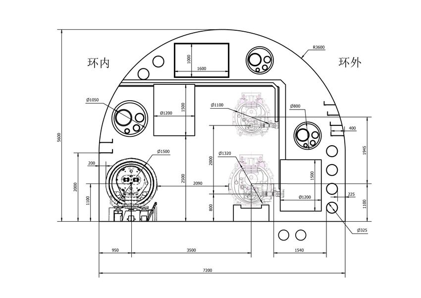
Tunnel Cross Section – RF Sections

 Drill/Blast Method

 7.2 m
 20
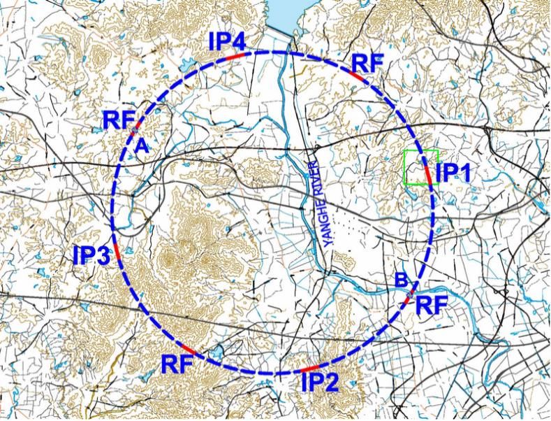
CEPC – Site Investigation
 300 km from Beijing
A good example is 秦皇岛: 3 hours by car; 1 hours by high speed train

W. Chou IAS Workshop, Jan 19-22, 2015 Y. F. Wang 21
Civil Construction

 22
Main Tunnel, Auxillary Tunnel & Bypass Tunnel

 23
Circular Lepton Colliders (K. Oide, RAST, volume 7)

 24
CEPC Design – Guidelines • Build an underground tunnel for a Higgs factory • Use the same tunnel for a future pp collider: The tunnel cross section should be big enough to accommodate an e+e- collider, a booster and a pp collider The straight sections should be long enough to accommodate large detectors and complex collimation systems of a pp collider It should allow to run both e+e- and pp experiments simultaneously Within the budget limit, the tunnel circumference should be made as large as possible • Keep options open for: Super Z e-p and e-A colliders Light source FEL • A possible timeline: A Preliminary Conceptual Design Report (Pre-CDR) this year Get ready for R&D to start in 2016 in the government’s 13th Five-Year Plan (2016- 2020) Get ready for construction to start in 2021 in the 14th Five-Year Plan (2021-2025) Get ready for experiments to start in 2028 in the 15th Five-Year Plan (2026-2030) W. Chou IAS Workshop, Jan 19-22, 2015 25
CEPC Design - Baseline • Tunnel circumference: ~54 km • Tunnel size: 6.0 m (LEP tunnel: 3.6 m) • 8 arcs and 8 straight sections: 4 straight for IPs and RF, another 4 for RF, injection and beam dump, etc. • A 6 GeV linac on the surface (with the option for an FEL in the future) • A full-energy 120 GeV Booster in the tunnel • A 240 GeV e+e- Collider in the same tunnel underneath the Booster • A single beam pipe for both e+ and e- beams (similar to LEP, CESR) • Synchrotron radiation budget: 50 MW per beam • Two SRF systems: Booster: 1.3 GHz 9-cell cavity, similar to the ILC, XFEL, LCLS-II Collider: 650 MHz 5-cell cavity, similar to the ADS, PIP-II W. Chou IAS Workshop, Jan 19-22, 2015 26
CEPC Design – Main Parameters Parameter Unit Value Parameter Unit Value Beam energy [E] GeV 120 Circumference [C] m 54752 Number of IP[NIP] 2 SR loss/turn [U0] GeV 3.11 Bunch number/beam[nB] 50 Bunch population [Ne] 3.79E+11 SR power/beam [P] MW 51.7 Beam current [I] mA 16.6 Bending radius [r] m 6094 momentum compaction factor [ap] 3.36E-05 Revolution period [T0] s 1.83E-04 Revolution frequency [f0] Hz 5475.46 emittance (x/y) nm 6.12/0.018 b IP(x/y) mm 800/1.2 Transverse size (x/y) mm 69.97/0.15 xx,y/IP 0.118/0.083 Bunch length SR [ss.SR] mm 2.14 Bunch length total [ss.tot] mm 2.65 lifetime due to radiative Bhabha Lifetime due to Beamstrahlung min 47 min 51 scattering [tL] RF voltage [Vrf] GV 6.87 RF frequency [frf] MHz 650 Harmonic number [h] 118800 Synchrotron oscillation tune [s] 0.18 Energy acceptance RF [h] % 5.99 Damping partition number [Je] 2 Energy spread SR [sd.SR] % 0.132 Energy spread BS [sd.BS] % 0.096 Energy spread total [sd.tot] % 0.163 ng 0.23 Transverse damping time [nx] turns 78 Longitudinal damping time [ne] turns 39 Hourglass factor Fh 0.68 Luminosity /IP[L] cm-2s-1 2.04E+34 W. Chou IAS Workshop, Jan 19-22, 2015 27
Main Technical Challenges for CEPC Common for both CEPC and FCC-ee: 1. IR optics with appropriate dynamic aperture for off-momentum up to 2% 2. Machine-detector interface (L* = 1.5 m) 3. HOM damper for the RF cavity High average beam current: 2 x 16.6 mA High HOM loss: 2 x 2.3 kW per cavity 40 K to 80 K 5 K to 8 K 2K HOM heat load distribution 3% 0.3% 0.1% Specific to CEPC (due to budget constraint): 4. Pretzel orbit (single beam pipe) 5. Low energy injection (6 GeV) to the Booster: Earth field effect: bend field ~30 Gs, measured earth field ~0.5 0.03 Gs W. Chou IAS Workshop, Jan 19-22, 2015 28
Beam-Beam Effect
Luminosity vs. Working point Momentum acceptance vs.
 Beam lifetime

 Luminosity vs. Beta*

 29
IR Optics
 L* = 1.5 m
 by*=1.2mm

W. Chou IAS Workshop, Jan 19-22, 2015 30
Dynamic Aperture of IR + Arc Linear Matrix

W. Chou IAS Workshop, Jan 19-22, 2015 31
Dynamic Aperture of the Entire Ring

W. Chou IAS Workshop, Jan 19-22, 2015 32
Machine Detector Interface

 33
Injectors

 Top-up Full-energy Injection Booster Cycle (0.1 Hz)
 800
 700
 600
 500
 B (Gs) 400
 300
 200
 100
 0
 0.00 2.00 4.00 6.00 8.00 10.00 12.00
 t (s)
W. Chou IAS Workshop, Jan 19-22, 2015 34
Injectors (cont…)

W. Chou IAS Workshop, Jan 19-22, 2015 35
CEPC Cryomodule Layout Tunnel outside Ceiling CEPC Booster 1.3 GHz Cryomodule Euro-XFEL/ILC/LCLS-II type Tunnel outside Ceiling 1.3 GHzModule Flange Ø1100 1.3 GHz Cavity in Helium Vessel CEPC Booster 1.3 GHz Cryomodule 8 1.3 GHz 9-cell cavities per module OD Ø240 980 Module Flange 2 HOM couplers per cavity 1.3Vacuum Vessel GHz Cavity in Helium Vessel 300 mm Ø1100 1260 Helium Gas 811.3 GHz 9-cell beamline HOM cavities absorberperatmodule 70 K OD OD Ø966 Ø240 Return Pipe 980 X module length: 12 m (no SCQ) 2 HOM couplers per cavity 300 mm Vacuum Vessel 1260 Helium Gas OD Ø966 Return Pipe 4 1 beamline modules HOM absorber per module at 70 K string module connectlength: without12cryo m (no SCQ) & vac interval 280 4 module modules per module string string length: 48 m Enlarge two- phase 8 800 800 connect modulewithout cryo strings: & vac interval 6+4x0.5 (IR1&3) 280 pipe and chimney. module string length: 48 m Omit 5K shield while 8 module strings: 6+4x0.5 (IR1&3) 800 800 keep 5K intercept for if in parallel power coupler. if in parallel> 1800 As simple 650 as possible. MHz Cavity OD Ø440 in Helium Vessel 650 MHz > 1800 CEPC Collider 650 MHz Cryomodule 650 MHz Cavity in Helium Vessel Vacuum Vessel scaled from 1.3 GHz cryomodule OD Ø440 OD Ø1160 300 mm Helium Gas Return Pipe CEPC Collider 650 MHz Cryomodule 1512 4 650 MHz 5-cell cavity per module Vacuum ModuleVessel Flange 300 mm OD Ø1160 Ø1320 Helium Gas 2 HOM couplers per cavity X Return Pipe 1512 42650 MHz 5-cell beamline HOMcavity per module absorbers at RT Module Flange module Ø1320 2 HOM couplers permcavity length: 10 12 380 2 beamline modulesHOM absorbers per module at RT string module modulelength: > 750 10 m 120 m string length: 12 380 8 module modulesstrings: per module string 6+4x0.5 (IR1&3) 1000 1000 module string length: 120 m > 750 8 module strings: 6+4x0.5 (IR1&3) Floor 1000 1000 36 Floor
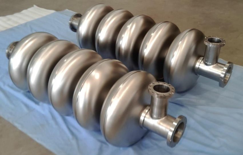
IHEP 1.3 GHz and 650 MHz Cavity

 1.3 GHz 9-cell cavity vertical test
 (VT) in 2013. In module horizontal
 test (HT), the cavity performance
 will have degradation.

 ILC TC-1 CEPC
 VT Eacc 20 MV/m 22 MV/m
 VT Q0 1.4E10 3E10
 HT Eacc 18 MV/m 20 MV/m
 HT Q0 1E10 2E10

 ADS 650 MHz β=0.82 5-cell cavity
 Vertical test soon

W. Chou IAS Workshop, Jan 19-22, 2015 37
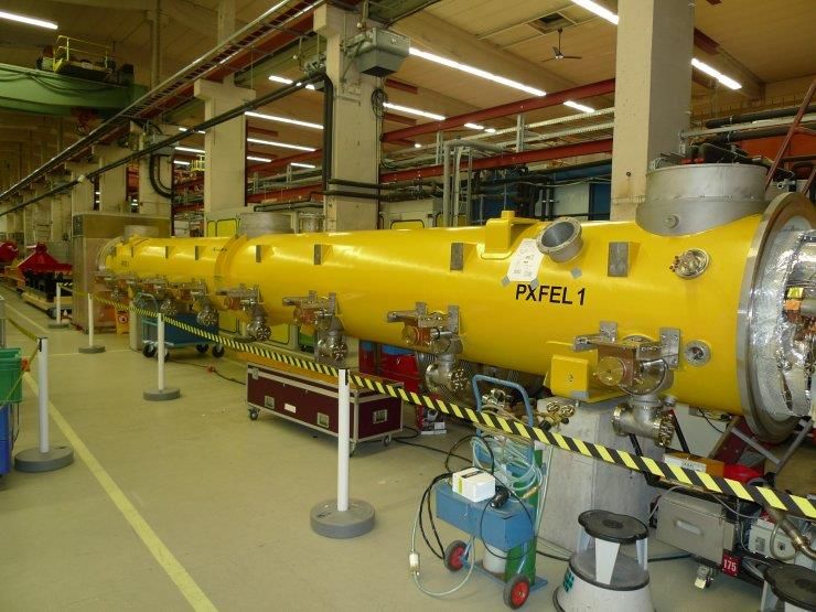
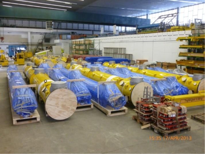
IHEP Cryomodules for XFEL
(58 modules, 12 m long each)

 38
Five-cell cavity with strong HOM damping HOM ports FPC port Six antenna-type couplers will be attached to the large diameter beam pipes and will provide strong HOM damping while maintaining good fill factor for the linac. Two HOM filters are currently under consideration: a high pass filter made of lumped elements and a ridge waveguide filter. Total HOM power to be extracted in eRHIC is about 7.3 kW per cavity. September 19, 2014 BNL3 cavity & eRHIC 39
SRF R&D Plan for the Project Timeline • The critical path of the project is to have a successful R&D for the SRF • CEPC will require two large SRF systems: Collider: 650 MHz, 384 cavities in 96 cryomodules Booster: 1.3 GHz, 256 cavities in 32 cryomodules • This would be the largest SRF installation in the world. To succeed with designing, fabricating, commissioning and installation of such a system, a significant investment in R&D, infrastructure and personnel is necessary. • The R&D has two parts: Prototyping as well as technology development for several critical components, in particular, the HOM damper Pre-series production: 15-20 1.3 GHz cavities and 30-35 650 MHz cavities A large RF facility similar to that in Jlab, Fermilab and DESY for cavity inspection and tuning set ups, RF lab, several vertical test stands, clean rooms, HPR systems, FPC preparation and conditioning facility, cryomodule assembly lines, horizontal test stations, high power RF equipment, a cryogenic plant, etc. Capable to assemble 1 Booster modules and 2 Collider module each month To have at least two vendors for each type of RF Personnel development 40
SRF R&D Program on CEPC Timeline
 2015

 2020

 2027
 R&D
Pre-studies Construction
 Engineering Design
(2013-2015) (2021-2027, 7 yrs.)
 (2016-2020, 5 yrs.)

 SRF SRF Initial Technology R&D
Pre-design (2016-2020, 5 yrs.)

HOM damping, high Q0 cavity, SRF Pre-Production R&D SRF Production and Installation
coupler window, heat load (2019-2022, 4 yrs.) (2023-2027, 5 yrs.)

 IHEP site infrastructure Large scale SRF lab (infrastructure) on CEPC site and in industry (2018)
CEPC SRF Team (~6) CEPC SRF Core Team (main ring 10 + booster 10 in parallel) (start from 2017)

Facility upgrade, additional space SRF ~ 200 FTEs (start from 2020), engineers and technicians

Components Prototyping & Performance Demonstration:
Cavity (four for each), helium vessel, vertical test
Power coupler (four for each), HOM dampers, tuners
Short (two-cavity) module for each type, horizontal test Booster SRF in three years (2023-2025):
 test two 1300 MHz cavities per week
Demonstrate Robustness of Fabrication and Assembly Processes of assemble and test one cryomodule per month
Cryomodule and its Components. Establish procedures, quality control Main ring SRF in four years (2023-2025):
steps, test set ups, assembly sequences, etc. for the production run. Build and test two 650 MHz cavities per week
test two booster cryomodules and three main ring cryomodules. assemble and test two cryomodules per month
Power Consumption

 location and electrical loads(MW)
 system Total
 ring Booster Linac BT IP
power source 230 15 2.1 247.1
cryogenics 16 2 1 19
power converter for magnets 60.5 13.2 1.2 1 1 76.9
experimental devices 14 14
dedicated services 15 5 1 1 2 24
utilities 55 10 2.5 1 2 70.5
general services 15 1 1 1 18
campus 30
Total 391.5 45.2 7.8 4 21 499.5

 42
Relative Power Consumption

 3% 2%
 9%
 10%

 Linac & transport lines
 6%
 Booster
 16% Magnet
5%
 SRF
 Cryogenics
 Regular electricity
 Utilities
 48%
 Detectors
Upgrade to SPPC

 44
Main Technical Challenges for SPPC • Accelerator technology SC magnet (increasing performance and decreasing costs) Synchrotron radiation and beam screen (reducing power consumption) Collimation (machine protection) • Accelerator physics IR design, low by* , dynamic aperture Synchrotron radiation, heat load and radiation damage lifetime Beam-beam e-cloud Impedance and instabilities Ground motion MDI and background Machine reliability Cooling • Non-technical: Government strategic plan for S/T investment Support from both HEP and non-HEP scientists 45
Four Colliders using SC Magnets

Tevatron HERA RHIC LHC

 All cosine theta, all NbTi
 46
(courtesy of Peter Lee, Applied SC Center of FSU) 47
And coated conductors of YBCO which
 approximate single crystals by the mile…….

The IBAD approach – ion-beam-assisted 40mm Cu The RABiTS CC
deposition of the textured template 2mm Ag
 ~ 1mm YBCO
 ~ 30nm LMO
 Copper Stabilizer
 ~ 30nm Homo-epi MgO Copper Stabilizer
 50-75
 50-75 mm mm
 ~ 10nm IBAD MgO
 ~ 7nm yttria Ag (
Superconductor Price Comparison Steve Gourlay – Superconductor price paid by LBNL to the US companies: Superconductor price quoted by the Chinese companies: • Bi-2223: RMB 15,000/kg USD 2,400/kg • YBCO: RMB 20,000/kg USD 3,300/kg 49
SJTU HTS Research Institute 上海超导联合研究院

 • Management committee and Department Dean in charge
 • Management committee: 4 persons from Shanghai Superconductor, 3
 persons from SJTU
 • Infrastructure and operating funds sponsored by Shanghai
 New Superconductor,
 • Company-like talent employment, promotion and reward system
 System • Research fund and job title fully supported by SJTU

 •研究院实行管理委员会领导下的院长负责制
 •管理委员会超导公司四席、交通大学三席
 •基础设施由超导公司捐建,运行经费由超导公司划拨
 新体制 •实行公司化的人员聘用、晋升、奖惩及薪酬制度
 新机制 •交通大学在经费和职称等方面给予超导研究院全面支持

2014年7月21日高能物理所汇报 联系方式:洪智勇,zhiyong.hong@sjtu.edu.cn
High Field 2-in-1 Common Coil Superconducting Magnet Division Dipole Design for Colliders Coil #1 Coil #2 Highest field R&W Nb3Sn dipole HTS tape common coil dipole A conductor friendly design Suitable for HTS coils – Roebel cable? Unfavorable orientation wrt field o However, think long term. Will Ic remain so anisotropic forever? Charlotte, NC, USA August 13, 2014 FCC Magnet Meeting Ramesh Gupta , BNL Slide No. 51
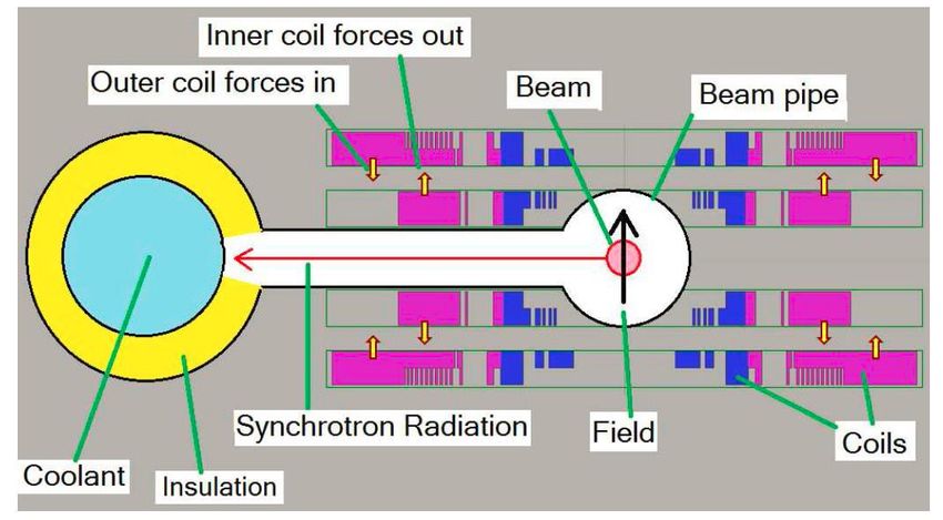
Seeking Solution for Severe SR 7TeV(LHC) 16.5TeV(HE-LHC) 50TeV(FCC) 31.7TeV(SPPC) SR power W/m 0.17w/m 4.35w/m 28.4w/m(100km) 45.8w/m(50km) 44.3w/m(83km) Critical energy 0.044 0.575 4.3(100km) 2.15 (keV) 5.5(83km) 40 K to 80 K 5 K to 8 K 2K Efficiency in W/W 16.4 197.9 703.0 • Possible solutions: High temperature beam screen (50 K) Open mid-plane dipole Anti-chamber in dipole Photon stops 52
(Bob Palmer, BNL, this workshop) 53
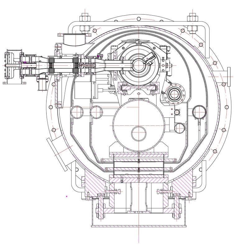
Conceptual design study of the 20-T dipole
 (Preliminary)
 20-T Nb3Sn + HTS dipole for SppC Open-plane design is under consideration
 Maximum space for beam pipes: 2 * Φ50 mm, with the To remove the synchrotron radiation heat
load line ratio of 85% @ 4.2K and the diameter of 900mm
 load at higher temperature

 Nb3Sn HTS Nb3Sn

 Nb3Sn HTS Nb3Sn Proposed by Ramesh Gupta, BNL

 Decay particles will deposit energy in a
 warm absorber that is sufficiently away
 from the superconducting coils or
 support structure.
R&D plan of the 20 T accelerator magnets
 (Preliminary)
• 2015-2020: Development of a 12-T operational field Nb3Sn
 twin-aperture dipole with common coil configuration and 10-4
 field quality; Fabrication and test of 2~3 T HTS (Bi-2212 or YBCO)
 coils in a 12-T background field and basic research on tape
 superconductors for accelerator magnets (field quality,
 fabrication method, quench protection).
• 2020-2025: Development of 15-T Nb3Sn twin-aperture dipole
 and quadrupole with 10-4 field uniformity; Fabrication and test
 of 4~5 T HTS (Bi-2212 or YBCO) coils in a 15-T background field.
• 2025-2030: 15-T Nb3Sn coils + HTS coils (or all-HTS) to realize
 the 20-T dipole and quadrupole with 10-4 field uniformity;
 Development of the prototype SppC dipoles and quadrupoles
 and infrastructure build-up.
 2015/1/31 55
Work Breakdown Structure (WBS)
1 合计 4 同步辐射装置 Light Sources
2 加速器 Accelerators 4.1 光束线站
2.1 加速器物理 4.2 不可预见费10%
2.2 高频系统 5 土建 Civil Construction
2.3 低温系统 5.1 地下建筑工程(钻爆法、6.5m)
2.4 磁铁系统 5.2 地面建筑
2.5 电源系统 5.3 独立费用
2.6 机械系统 5.4 其他费用
2.7 真空系统 不可预见费10%
 5.5
2.8 束测系统
 6 通用设施 Utilities
2.9 准直
 6.1 供配电系统
2.10 控制系统
 6.2 水冷系统
2.11 辐射防护
2.12 直线加速器 6.3 通风空调系统
2.13 功率源 6.4 压缩空气
2.14 增强器 6.5 独立费用
2.15 超导加速器磁铁(SPPC)R&D 6.6 其他费用
2.16 不可预见费10% 6.7 不可预见费10%
3 探测器 Detectors
3.1 径迹探测器(TPC)
3.2 顶点探测器(VTX)
3.3 量能器(电磁+强子)
3.4 Muon探测器
3.5 探测器磁铁
3.6 物理模拟与软件组
3.7 计算资源系统
3.8 触发与数据获取系统
3.9 不可预见费10%

W. Chou IAS Workshop, Jan 19-22, 2015 56
CEPC Relative Cost Estimate

 10%
 4%
 26%
 2.4%

 10%

 2%

 12% 19%
 12%

W. Chou IAS Workshop, Jan 19-22, 2015 57
Global HEP Strategy

ICFA statement in February, 2014 at DESY
ICFA encouraged the two studies (FCC and CEPC-SPPC) to work as close
together as possible, with the following statement:
ICFA supports studies of energy frontier circular colliders and encourages
global coordination.

ICFA statement in July, 2014 at Valencia
ICFA endorses the particle physics strategic plans produced in Europe, Asia
and the United States and the globally aligned priorities contained therein.
Here, ICFA reaffirms its support of the ILC, which is in a mature state of
technical development and offers unprecedented opportunities for
precision studies of the newly discovered Higgs boson. In addition, ICFA
continues to encourage international studies of circular colliders, with an
ultimate goal of proton-proton collisions at energies much higher than
those of the LHC.
 58
Summary • A Preliminary Conceptual Design Report (Pre-CDR) is completed. There will be a review next month by an international committee chaired by Prof. Oide (KEK). The report will be released after the review. • It is by no means an optimized design. Rather, it provides a baseline design that is consistent and able to reach the design goal. • The design is focused on the CEPC, but it is compatible to an upgrade to the SPPC. • The critical R&D items have been identified. • The next steps: To submit the report to the government and get into the 13th Five-Year Plan (2016-2020). To carry out an R&D plan for key technical systems. To form international collaboration with other HEP laboratories and institutions. To organize a series of mini-workshops, each to address a specific subject (SC magnet, SRF, IR optics, MDI, pretzel, etc.). 59
Questions?

W. Chou Aspen Winter Conference, Jan 26 – Feb 1, 2015 60
You can also read