Payload User Guide LAUNCH WITH - Firefly Aerospace
←
→
Page content transcription
If your browser does not render page correctly, please read the page content below
LAUNCH WITH

Payload User Guide
Contents
     1―FIREFLY OVERVIEW ................................................................................................................................... 3

            Contact .................................................................................................................................................... 3

     2―Alpha Launch Vehicle ................................................................................................................................ 5

            Performance ........................................................................................................................................... 6

            Flight Profile ............................................................................................................................................ 7

            Payload Injection & Separation .............................................................................................................. 8

            Payload Fairing ........................................................................................................................................ 9

            Payload Accommodation and Interfaces .............................................................................................. 10

            Payload Configurations ......................................................................................................................... 11

            Alpha Electrical Interfaces .................................................................................................................... 12

     3―Flight Environments ................................................................................................................................ 13

            Quasi-Static Acceleration Loads............................................................................................................ 13

            Acoustics ............................................................................................................................................... 14

            Shock ..................................................................................................................................................... 15

            Random Vibration ................................................................................................................................. 16

            Equivalent Sine Vibration...................................................................................................................... 17

            Pressure and Venting ............................................................................................................................ 19

            Thermal and Cleanliness ....................................................................................................................... 20

            Radio Frequency and EMI/EMC ............................................................................................................ 21

     4―Operations .............................................................................................................................................. 22

            Standard and Non-Standard Services ................................................................................................... 22

            Payload Processing Flow ....................................................................................................................... 23

            Launch Campaign Timeline ................................................................................................................... 24

     5―Mission .................................................................................................................................................... 25

            Customer Deliverables .......................................................................................................................... 25

            Mission Management ........................................................................................................................... 26

            Safety Requirements............................................................................................................................. 26

            Hazardous Systems and Operations ..................................................................................................... 26

Page 1                 FIREFLY AEROSPACE, INC.                                                                                                        Alpha | Contents
Waivers ................................................................................................................................................. 26

      6―Facilities .................................................................................................................................................. 27

             Corporate Headquarters ....................................................................................................................... 27

             Production and Test Facilities ............................................................................................................... 27

             Launch Complexes ................................................................................................................................ 28

             Horizontal Integration Facility .............................................................................................................. 31

             Payload Processing Facility ................................................................................................................... 32

             Infrastructure ........................................................................................................................................ 32

      7―References .............................................................................................................................................. 33

             Acronyms .............................................................................................................................................. 33

             List of Figures ........................................................................................................................................ 34

             List of Tables ......................................................................................................................................... 35

                                                                  Revision History
                                    Date                                     Version                                                      History
                              March 2018                                           1.0                                             First Release
                              August 2019                                          2.0                                            Updated Release
                              March 2022                                           3.0                                            Updated Release
                               April 2022                                          3.1                                           Improved Release

The Alpha Payload User’s Guide - Version 3.1 has been cleared for open publication by the Defense Office of
Prepublication and Security Review, Department of Defense, as stated in letter 22-S-1137, dated March 18, 2022.

Page 2                  FIREFLY AEROSPACE, INC.                                                                                                      Alpha | Contents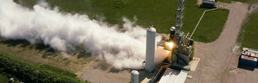
1―FIREFLY OVERVIEW

                                              Figure 1. Firefly Family

     Firefly was founded to provide economical and reliable access to space through the design, manufacture,
     and operation of launch vehicles and spacecraft. To reduce risk and increase reliability, Firefly employs a
     vertically integrated manufacturing process while leveraging high maturity COTS components. The
     technologies employed in the flagship Alpha vehicle provide a clear pathway for future incremental
     improvements in capability, and expansion of the Firefly Beta launch vehicle.

     Though this guide is specific to the Alpha Launch Vehicle (LV), Firefly offers a family of other space
     transportation services. The Alpha and Beta launch vehicles are the foremost choice for small and medium
     launchers. The Space Utility Vehicle (SUV) offers in-space transportation, maintenance, and refueling
     options. The Blue Ghost lunar lander completes the end-to-end transportation service with its entry,
     descent, and landing capabilities.

 Contact
     Firefly Aerospace, Inc.

     1320 Arrow Point Drive, Suite 109 Cedar Park, TX 78613

     Web: www.firefly.com

     E-Mail: launch@firefly.com

Page 3           FIREFLY AEROSPACE, INC.                                                     Alpha | Firefly Overview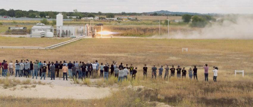
Alpha provides low-cost launch capability for small satellite customers at a price of $15M for dedicated
     commercial launch services. Alpha is designed to be the world’s most reliable, responsive, and
     operationally capable launch option within the small launch vehicle class. Supported by Firefly’s
     streamlined approach to mission planning, integration, and launch, Alpha is a well-rounded choice for
     commercial, civil, and national security missions.

                                     Table 1. Alpha Launch Vehicle Specifications
                           Performance                           Alpha
                        Payload [SSO, 500km]                       745                 kg
                                                          860 (avail. 06/2023)
                        Payload [LEO, 200km]                      1,170                kg
                                                          1,375 (avail. 06/2023)
                           Architecture
                         Gross Lift-Off Weight                   54,120                kg
                               (GLOW)
                          Number of Stages                          2

                             Total Length                         29.48                m

                            Max Diameter                           2.2                 m

                              Structure                       All Composite

                            Propulsion
                               Oxidizer                            LOX

                                 Fuel                             RP-1

                         Max Thrust [Stage 1]                   801 / 180           kN / klbf

                         Max Thrust [Stage 2]                   70 / 15.7           kN / klbf

     Examples of Firefly efficiencies:
                  • Streamlined Coupled Loads Analysis (CLA) and Interface Control Document/Drawings (ICD) to
                    decrease mission analysis completion times from months to weeks or days, depending on
                    payload complexity
                  • 100% carbon composite airframe including state-of-the-art linerless, cryogenic propellant tanks
                  • Stage 1 Reaver engines and stage 2 Lightning engines with a patented tap-off cycle

Page 4           FIREFLY AEROSPACE, INC.                                                    Alpha | Firefly Overview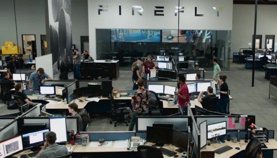
2―ALPHA LAUNCH VEHICLE
_

        Payload Fairing

                                                                                                                   Payload Segment

                                                                                                                                     5.21 m [17.09 ft]
        Carbon Composite Structure
        All Pneumatic Low Shock Fairing Separation

        Payload Attach Fitting (PAF)                                       Standardized Secondary
        38.81” Bolt Circle Interface                                       Payload Adapter
                                                                           6 Ports with 8” Bolt Circle Interface

        Stage 2 Avionics                                                   Stage 2 LOX Tank
        Flight Computer
                                                                           All Composite Construction

                                                                                                                                     [5.37 m [17.62 ft]
        S-Band Transmitters
                                                                           Design MEOP 65 psi
        GPS/IMU Navigation

                                                                                                                   Stage 2
        Power Conditioning & Distribution Unit (PCDU)
                                                                           Stage 2 Helium Tank
        Data Acquisition Chassis (DAC)
                                                                           Aluminum Liner
        Lithium Polymer Batteries
                                                                           Design MEOP 5500 psi
        Flight Termination System

        Interstage                                                         Stage 2 Fuel Tank
        Hot Gas Stage Separation                                           All Composite Construction
        Carbon Composite                                                   Design MEOP 55 psi

        Stage 2 Lightning Engine                                           Stage 2 Nitrogen Tank
        Qty Engines: 1                                                     Aluminum Liner
        Propellant: LOX/RP-1                                               Design MEOP 5500 psi
        Thrust: 70 kN [15.7 klbf] (vac)
        Isp: 322 seconds (vac)                                             Stage 1 LOX Tank
                                                                           All Composite Construction
                                                                           Design MEOP 70 psi
        Stage 1 Avionics

                                                                                                                                     18.9m [62.02 ft]
        Power Conditioning & Distribution Unit (PCDU)                      Stage 1 Helium Tanks
        Data Acquisition Chassis (DAC)

                                                                                                                   Stage 1
                                                                           Qty Tanks: 4
        Lithium Polymer Batteries
                                                                           Aluminum Liner
                                                                           Design MEOP 5500 psi

                                                                           Stage 1 Fuel Tank
                                                                           All Composite Construction
                                                                           Design MEOP 75 psi
         Alpha Launch Vehicle
         GLOW 54,120 kg [119,314 lbm]                                      Stage 1 Reaver Engine
         Height 29.48 m [96.7 ft]                                          Qty Engines: 4
         Stage 1 Dry Mass 2,895 kg [6,382 lbm]                             Propellant: LOX/RP-1
         Stage 2 Dry Mass 909 kg [2,006 lbm]                               Thrust: 801 kN [180 klbf] (vac)
                                                                           Isp: 296 seconds (vac)

                                                 Figure 2. Alpha Launch Vehicle

    Page 5             FIREFLY AEROSPACE, INC.                                                Alpha | Alpha Launch Vehicle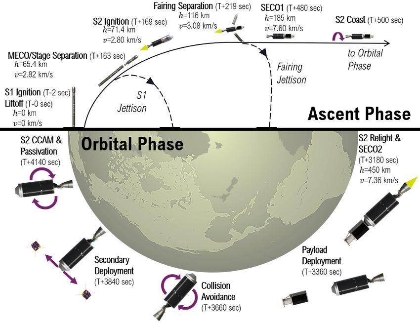
Performance
     The figures below show Alpha’s performance capabilities from eastern and western ranges. These payload
     masses to orbit represent the total payload mass including the spacecraft, separation system, and
     adapter.

                                       800

                                       750

                                       700
                   Payload Mass [kg]

                                       650

                                       600
                                                                                                                    i = 70°
                                                                                                                    i = 80°
                                       550
                                                                                                                    i = 90°

                                       500                                                                           i = 100°

                                                                                                                     i = 110°
                                       450
                                             100         300          500                   700          900              1100
                                                                            Altitude [km]

                                        Figure 3. Alpha West Coast Performance Capability for Common Inclinations

                                 1050

                                 1000

                                       950

                                       900
             Payload Mass [kg]

                                       850

                                       800
                                                                                                                      i = 29°
                                       750
                                                                                                                      i = 38°
                                                                                                                      i = 45°
                                       700
                                                                                                                      i = 53°
                                       650                                                                            i = 60°

                                       600
                                             100   200   300   400     500       600         700   800    900      1000       1100
                                                                             Altitude [km]

                                        Figure 4. Alpha East Coast Performance Capability for Common Inclinations

Page 6                             FIREFLY AEROSPACE, INC.                                                      Alpha | Alpha Launch Vehicle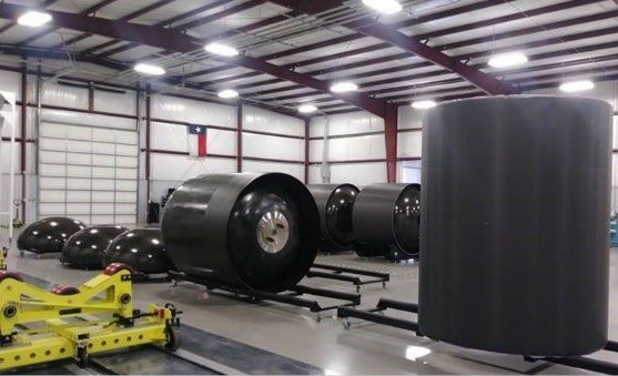
Flight Profile
     The axis definitions in Figure 5 are used throughout the remainder of this document to specify and
     reference payload environments, loads, flight, and test requirements.

                                     Figure 5. Alpha Vehicle Coordinate Frame

     Figure 6 illustrates a representative flight profile of an Alpha launch vehicle 2-burn mission. Although all
     missions follow a similar profile, timing and altitude for key events may vary per mission.

                                     Figure 6. Alpha Direct Insert Flight Profile

Page 7           FIREFLY AEROSPACE, INC.                                                Alpha | Alpha Launch Vehicle
Payload Injection & Separation

  Precise pointing and orbital insertion are provided by a
  navigation control module consisting of an Inertial              Table 2. Payload Injection and Separation
  Measurement Unit (IMU) and Global Positioning                            Payload Injection Accuracy
  System (GPS) receiver on the upper stage of the launch
                                                                  ± 5 km perigee altitude
  vehicle. The values in Table 2 represent three-sigma
  dispersions for a LEO mission with a second stage               ± 15 km apogee altitude
  Probability of Command Shutdown of 99.7%.
                                                                  ± 0.1 deg inclination

                                                                         Payload Separation Parameters
  For missions requiring orbits above 400 km, Alpha’s             > 1 ft/sec [0.348 m/sec] separation velocity
  second stage inserts into a low elliptical transfer orbit,
                                                                  < 1.4 deg pointing accuracy on each axis
  coasts to apogee, and then initiates a second burn
  maneuver to circularize into the final desired orbit.           < 1 deg/sec stability in pitch, yaw, and roll

                                            Figure 7. Alpha Payload Section

Page 8            FIREFLY AEROSPACE, INC.                                                   Alpha | Alpha Launch Vehicle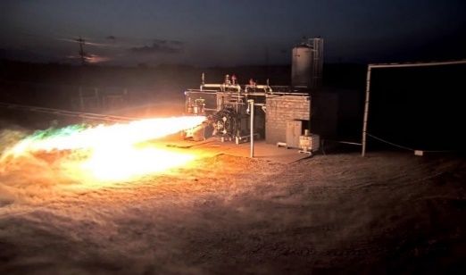
Payload Fairing
     The Alpha payload fairing (PLF) is a carbon composite structure developed, manufactured, and qualified
     by Firefly. It measures 2.2 m (7.2 ft) in diameter, and 5 m (16.4 ft) in height. The fairing separation system
     employs a debris free, low-shock pneumatic separation system fully tested prior to each flight.

     The payload fairing remains latched until launch ascent free molecular heating is below 1,136 W/m2.
     Immediately thereafter, Alpha initiates a low shock separation event to deploy the two fairing halves from
     the payload attach fitting (PAF) and LV upper stage.

     The dynamic payload envelope accounts for dynamic movement of the fairing and payload relative to one
     another, acoustic isolation panels, thermal expansion, and manufacturing tolerances. To avoid coupling
     with low frequency LV modes and violating this envelope, the SC should be designed to fundamental
     frequencies of greater than 8 Hz lateral and 25 Hz axial.

                                 Figure 8. Alpha Payload Fairing Dynamic Envelope

Page 9           FIREFLY AEROSPACE, INC.                                                  Alpha | Alpha Launch Vehicle
Payload Accommodation and Interfaces
The Alpha vehicle features a standard 38.81” ESPA bolt pattern interface which is compatible with the
industry standard 937mm adapter and other Firefly-specific dispenser structures. Firefly can
accommodate all industry standard interfaces and separation systems currently flight proven, depending
on customer needs. Accommodations outside the standard bolt pattern may be negotiated and should be
discussed early in the mission planning process.
1000
800
Spaecrcraft Mass (kg)
600
400
200
0
0 0.5 1 1.5 2
Distance Above the Separation Plane (m)
Figure 9. Allowable Payload CG Height
Figure 10. Payload Interface Dimensions in Launch Vehicle Coordinate Frame
Page 10 FIREFLY AEROSPACE, INC. Alpha | Alpha Launch VehiclePayload Configurations
Firefly offers several standardized payload configurations. Each configuration is compatible with industry
standard separation systems. Firefly also has the ability to design customized adapters. The available
primary payload volume for each configuration is shown in green in Figure 11 below.
Dedicated Triple Single Multiple Dual
Mission ESPA Rideshare Rideshare PAF
Figure 11. Common Payload Attach Fitting Configurations
Page 11 FIREFLY AEROSPACE, INC. Alpha | Alpha Launch VehicleAlpha Electrical Interfaces
The Alpha launch vehicle provides an electrical interface between the spacecraft and the customer ground
support equipment. The Alpha LV is equipped with one or two connector(s) totaling 30 pins between the
spacecraft and the vehicle; this includes both a flight interface and a ground interface. The flight interface
with the spacecraft is for separation commands and monitoring. The ground interface is available up to T-
0 via a quick-disconnect umbilical on the Alpha payload fairing.
Alpha’s standard electrical interface for the primary payload is compatible with all industry standard
separation systems and spacecraft customer needs. Additional electrical interface options are available
based on customer mission unique needs.
Flight Interface
• Two separation loops for spacecraft (SC) to detect separation
• Eight redundant 28 VDC separation commands:
o 5 amps each
o Minimum pulse of 35ms up to 500ms
o Up to 4 signals simultaneously within 10ms
o Inhibits in accordance with AFSPCMAN 91-710
Ground Interface
• Ten 20 AWG twisted shielded pairs
o Suitable for RS- 422 serial or ethernet communication
• Six 16 AWG twisted shielded pairs
o Suitable for battery charging
Figure 12. Alpha Electrical Interface
Page 12 FIREFLY AEROSPACE, INC. Alpha | Alpha Launch Vehicle3―FLIGHT ENVIRONMENTS
Alpha LV loads and environments are less than those historically produced by small to medium class
launch vehicles, limiting the need for payloads to expend resources for additional isolation systems or
other mitigation techniques. Key design elements to reduce environmental levels include eliminating the
use of pyrotechnic devices near the payload, near full coverage (5 cm, 2” thick) acoustic panels in the
fairing, pad-based water suppression, and advanced composite structures that mitigate transmission of
LV produced loads and environments. Coupled Loads Analysis (CLA) and integrated thermal analysis
models are used to ensure full compatibility with each SC design. All payloads shall be qualified to these
minimum levels prior to launch.
Quasi-Static Acceleration Loads
Figure 13 illustrates the maximum predicted axial and lateral quasi-static loads induced to the payload
during launch. Payloads desiring launch on Alpha should account for these worst-case loads. These loads
originate from a complex mix of vehicle accelerations, pitch maneuvers, aerodynamic buffeting, and
coupling of loads. The completion of the mission specific CLA analyses will confirm if potential loads can
be reduced for a specific mission.
Figure 13. Alpha Maximum Quasi-Static Load Factors
Page 13 FIREFLY AEROSPACE, INC. Alpha | Flight EnvironmentsAcoustics
Alpha LV acoustic protection is intended to provide an Overall Sound Pressure Level (OASPL) below 139
dB. Currently predicted sound pressure levels within the PLF are well below this value due to the use of
water deluge. The fairing will be equipped with acoustic foam to further reduce predicted values.
Figure 14. Alpha Maximum Predicted Acoustic Environment
Table 3. Alpha Sound Pressure Levels
Center Sound Pressure Center Sound Pressure
Frequency [Hz] Level [dB] Frequency [Hz] Level [dB]
31.5 106.3 630 126.7
40 111.4 800 124.8
50 113.9 1000 122.4
63 118.2 1250 118.6
80 120.6 1600 114.6
100 122.4 2000 110.0
125 123.5 2500 105.8
160 125.5 3150 102.6
200 126.5 4000 99.4
250 126.8 5000 97.3
315 127.1 6300 95.2
400 126.8 8000 93.1
500 126.8 10000 91.0
OASLP [dB] 136.5
Page 14 FIREFLY AEROSPACE, INC. Alpha | Flight EnvironmentsShock
The maximum shock environment at the payload interface occurs during payload deployment. Shock
levels at the payload separation interface due to hold-down release, stage separation, engine ignition and
cutoff, and payload fairing separation are all maintained below a maximum acceleration of 750 g’s at 1400
Hz. Shock environments heavily depend on the mission-specific payload separation system. The shock
environment below is for the usual shock at the payload separation plane.
Figure 15. Alpha Maximum Predicted Shock Response Spectrum
Table 4. Alpha Frequency and Acceleration Levels
Natural Frequency [Hz] Maximum Acceleration [g]
100 30
100 - 1,000 See Figure
1,400 - 10,000 750
Page 15 FIREFLY AEROSPACE, INC. Alpha | Flight EnvironmentsRandom Vibration
Payloads are subjected to a combination of engine vibrations, vehicle structural modes, acoustics, and
aerodynamic forces. The intensity of these vibrations is highly dependent on the payload mass, stiffness,
and the interface between the payload and the launch vehicle. The predicted maximum random vibration
Power Spectral Density (PSD) is for a payload mass of 90 kg or greater.
Figure 16. Alpha Random Vibration Environment Plot
Table 5. Alpha Random Vibration Frequency and PSD Levels
Frequency [Hz] Alpha PSD Level [g2/Hz]
20 - 80 0.00125
80 – 200 Hz See Figure
200 – 1600 Hz 0.01
1600 – 2,000 Hz See Figure
2,000 Hz 0.00644
gRMS [g] 4.32
Page 16 FIREFLY AEROSPACE, INC. Alpha | Flight EnvironmentsEquivalent Sine Vibration
Maximum Alpha sinusoidal vibration environments envelope all stages of flight. These represent the
maximum predicted sine vibe environments for the payload, but a CLA analysis will be needed to prove
further compliance.
Figure 17. Alpha Axial Sine Vibration Environment
Table 6. Axial Sine Frequency and Acceleration Levels
Frequency [Hz] Acceleration [g]
5 0.45
25 0.45
45 0.9
55 0.9
80 0.7
100 0.7
Page 17 FIREFLY AEROSPACE, INC. Alpha | Flight EnvironmentsFigure 18. Alpha Lateral Sine Vibration Environment
Table 7. Lateral Sine Frequency and Acceleration Levels
Frequency [Hz] Acceleration [g]
5 0.05
20 0.05
35 0.15
60 0.15
70 0.1
100 0.1
Page 18 FIREFLY AEROSPACE, INC. Alpha | Flight EnvironmentsPressure and Venting
During ascent, the fairing will relieve internal pressure through one-way vents located at the aft end of
the payload fairing. The pressure decay rate will not exceed -0.3 psi/second, except for a brief period
during transonic flight, when the decay rate is not expected to exceed -0.9 psi/second (not depicted in the
plot).
Fairing Internal Pressure
Pressure Decay Rate
Figure 19. Alpha Payload Fairing Venting Environment
Page 19 FIREFLY AEROSPACE, INC. Alpha | Flight EnvironmentsThermal and Cleanliness
The Alpha launch vehicle provides the payload with standard thermal, humidity, and High Efficiency
Particulate Air (HEPA) clean controlled environments from encapsulation through liftoff. Firefly can
accommodate contamination-sensitive payloads from integration in the Payload Processing Facility (PPF),
roll-out to the launch pad, and through launch. For payloads with more extensive requirements, Firefly
can provide additional cleaning, filtration, contamination mitigation protocol, and verification services.
Table 8. Thermal and Cleanliness Environments
Cleaning and Materials Payload Rollout Flight
Processing and Pad
Ops
All major surfaces including the PLF, Acoustic
Blankets, and PAF are Visibly Cleaned to IEST-
STD-CC1246D
Major materials within line of sight of the
payload comply to 1% TML 0.1% CVCM
Mission specific cleaning down to 500A
available
Air Cleanliness
ISO 8 (Class 100K) HEPA air in PPF and PLF
GN2 purge available as an upgrade
Prevention of high velocity air impingement
directly onto the payload
Air ventilates out through ports on the PLF
Mission specific ISO 7 (Class 10k) available
Temperature
Temperature controlled air 10-21 deg C [50-70
deg F]
Maximum FMH < 1,136 W/m2 [0.1 BTU/ ft2 /s]
Relative air humidity controlled from 20-60%
PLF internal surface temperature < 93 deg C
[200 deg F]
Page 20 FIREFLY AEROSPACE, INC. Alpha | Flight EnvironmentsRadio Frequency and EMI/EMC
Alpha can accommodate payloads which are powered on during launch, but for standard operations it is
recommended payloads be powered off during launch to reduce the potential for interference or damage
caused by Radio Frequency (RF) or Electro Magnetic Interference (EMI). The Alpha vehicle is capable of
interleaved telemetry for payload monitoring during flight. Customers must ensure payload components
or material constituents sensitive to RF transmissions are compatible with the radio frequency and
EMI/EMC environment provided in the table below.
Table 9. Alpha Radio Frequency and EMI/EMC Environments
Function Frequency
S-Band Transmitter 2.2 – 2.29 GHz
Avionics Power Switching 100 kHz - 400 kHz, 440 kHz, 660 kHz, 960 kHz
GPS L-Band Receiver L1: 1575.42 MHz
L2: 1227.60 MHz
L5: 1176.45 MHz
UHF Receiver 421 MHz
Page 21 FIREFLY AEROSPACE, INC. Alpha | Flight Environments4―OPERATIONS
Standard and Non-Standard Services
As part of the launch package, Firefly offers the standard services listed below. Firefly also offers mission
unique services upon request. These non-standard services may have impacts to schedule and cost.
Requests for mission unique services should be discussed early in the mission planning process.
Standard Services
• Dedicated Firefly Mission Manager
• Development of a mission-specific Interface Control Document (ICD)
• Launch vehicle licensing, including FAA and Range Safety Documentation
• Preliminary and final modeling and analysis of the integrated mission, including performance analysis, CLA,
and thermal modeling
• Fit Check verification of the Payload to the PAF
• Certified ISO 8 (Class 100K) cleanroom for payload to PAF integration areas, encapsulation, and through
launch
• Mission dress rehearsal for key launch personnel
• Payload access prior to payload fairing closure
• Post-flight launch services, including payload separation confirmation, delivery of the Post-Flight Data
Package, Payload Environment Report, and final deployment Orbital Parameter Message (OPM)
Mission Unique Services
• Separation system provided by Firefly
• Customized or multi-payload dispenser
• Payload qualification support for regulatory compliance
• Certified ISO 7 (Class 10K) cleanroom for payload to PAF integration areas and encapsulation
• Contamination control analysis
• Payload hazardous fueling and pressurization accommodations
• Payload access after payload fairing closure
• Dedicated payload GN2 purge and fairing thermal environment control, up to T-0
• RF Transmission after payload encapsulation, and before payload separation
• Re-Radiation System
• Payload-facing mounted cameras
Additional services may be available upon request.
Page 22 FIREFLY AEROSPACE, INC. Alpha | OperationsPayload Processing Flow
Payload Arrival
The payload arrives at the Payload Processing Facility (PPF) and is lifted from the transportation carrier by
lift truck or overhead crane located within the airlock. The payload is removed from its shipping container
and readied for checkouts. Once checkouts and fueling are complete, combined SC and LV operations
begin with mating of the SC to the PAF. Once the payload is fully assembled onto the PAF and any
additional services performed, it is then ready for encapsulation.
Payload Encapsulation
Payloads are encapsulated within the payload fairing in a vertical orientation. Once encapsulated, a
continuous supply of HEPA filtered and temperature-controlled air is supplied to the PLF. Direct airflow
impingement upon sensitive components is minimized. Then the encapsulated payload is broken over to
a horizontal position and mated to the LV. The encapsulated payload remains in the horizontal position
until the integrated launch vehicle is rolled to the launch pad and erected to vertical position prior to
launch.
Payload Fueling
As a non-standard option; hazardous, green, other propellants, and pressurization accommodations may
be provided by Firefly. Depending on the propellant, these accommodations may take place at third-party
facilities prior to transportation to the launch complex. Propellant loading details will be coordinated as
part of tailored mission support to the payload.
Page 23 FIREFLY AEROSPACE, INC. Alpha | OperationsLaunch Campaign Timeline
Each Firefly mission follows a standard mission timeline. Flexibility is offered for customers needing an
expedited schedule and should be discussed early in the mission planning process. All dates provided in
the table below are intended as guidelines, and not firm constraints.
Table 10. Notional Launch Campaign Timeline
Schedule Event
L-18 m Initial Customer Contact and Completion of the Payload
Questionnaire
L-14 m Signing of Launch Agreement and Down Payment
L-12 m Kickoff Working Group and Delivery of Payload Data
Package
L-9 m Firefly Delivery of Preliminary Mission Analysis
L-8 m Mission Integration & Ground Operations Working
Group
L-6 m Fit Check (Flight or Mass Simulator)
L-3 m Firefly Delivers Final Mission Analysis
L-6 w Commencement of Launch Campaign
L-4 w Customer Delivery of Payload
L-2d Launch Readiness Review
L-0 Launch
L+1 h Final Confirmation of Payload Separation and State
Vector
L+1 w Mission Data Review
Page 24 FIREFLY AEROSPACE, INC. Alpha | Operations5―MISSION
Customer Deliverables
Table 11. Customer Deliverables
Deliverable Description
Completed Payload An important first step for mission planning is the
Questionnaire completion of Firefly’s Payload Questionnaire. This is
provided by the Mission Manager and gives necessary
insight into the mission requirements.
Payload Safety Data Safety documentation and data to support Range
Package Safety operations and launch planning are requested
early in the mission planning process. It is the
customer’s responsibility to supply all design,
qualification, and acceptance test information for all
hazardous elements of the payload.
Customers are expected to complete inputs to the
Missile System Prelaunch Safety Package (MSPSP)
using the template provided by Firefly. The Firefly
Mission Manager integrates this information into both
the Federal Aviation Administration (FAA) licensing
application and the Range Safety Review Package.
Engineering Data The Engineering Data Package includes, but is not
Package limited to:
• CAD (inclusive of separation systems and
appendages)
• Thermal and Structural Models
• Archimedes Volume
• Emitter Characteristics
• Mass Properties Report
• Payload Analysis and Test Report
Any requests to operate outside of standard
environmental parameters specified herein must be
included.
Payload Processing A detailed Payload Processing Plan including any
Plan requests for non-standard services pertaining to
payload processing and launch operations.
Mass Model A mass model of the payload is to be provided by the
customer for fit checks. Mass models should show
interfaces representative to flying on Alpha.
Page 25 FIREFLY AEROSPACE, INC. Alpha | MissionMission Management
Each customer is assigned a Firefly Mission Manager (FMM), who will remain the direct point-of-contact
throughout the mission planning and launch process. Customers can expect transparency and open
communication from their FMM. The FMM works closely with their customer counterpart mission
manager, ensuring all facets of the mission planning and integration process are completed in a timely
manner. The FMM holds weekly mission integration meetings to keep an open discussion with the
customer. In addition to ensuring a seamless integration process to the launch vehicle, the FMM is also
the key interface to both the Firefly Launch Campaign Manager and the Range Safety Officer. The Launch
Campaign Manager interface exists to accommodate the SC and customer needs at launch site facilities.
The Range Safety Officer ensures compliance to all ground and flight safety requirements.
Safety Requirements
Safety is paramount in the mission planning and launch process. The customer’s Mission Manager, along
with the Mission Assurance team, will ensure payloads meet all safety requirements throughout the
design and launch planning process. Firefly will serve as a direct liaison between all customers and range
safety officials.
It is mandatory for customers to be in compliance with applicable AFSPCMAN 91-710 requirements, as
well as FAA 14 CFR, Part 400 for payload development, including the design of both flight and ground
systems. Customers are responsible for providing inputs to the Firefly MSPSP during early stages of
mission planning as part of Firefly’s Safety Data Package.
Customers are responsible for obtaining their own remote sensing, radio frequency approvals, and
ensuring their payload meets all launching states involved in their mission's insurance requirements.
Hazardous Systems and Operations
Payloads qualifying as a hazardous system or requiring hazardous operations outside of Firefly’s Standard
Service Package will require both Firefly and range safety approval prior to performing the operation or
conducting launch. The customer’s payload classification will be determined early in the mission planning
stages, to ensure proper permissions are granted.
Waivers
In the event systems or operations do not meet safety requirements but are believed to be acceptable for
ground and launch operations, Range Safety officials may grant a waiver. It is the policy of both Firefly and
Range Safety that waivers are used as a recourse and are not considered standard practice.
Page 26 FIREFLY AEROSPACE, INC. Alpha | Mission6―FACILITIES
____________________________________________________________________________________________________________________________________________________________________________________________________________________________________________________________________________________________________________________________________________________________________________________________________________________________________________________________________________________________________________________________________________________________________________________________________________________________________________________________________________________________________________________________________________________________________________________________________________________________________________________________________________________________________
Corporate Headquarters
Firefly’s Corporate Office is headquartered in Cedar Park, Texas. It is an open engineering environment to
encourage collaboration. Headquarters also houses the main Mission Control Center (MCC) where major
stage tests, operations, and launch can be monitored and supported.
Figure 20. Firefly’s Texas Headquarters, Production, and Test Facilities
Production and Test Facilities
LV production, integration, and testing are conducted in Briggs, Texas, at a 200-acre facility 30 minutes
north of Firefly Headquarters. The test site is fully staffed and incorporates multiple facilities including a
10,000 ft2 test control and fabrication building, a 2,500 ft2 surface finish shop, and a 30,000 ft2 production
shop. The site includes several operational test stands for engine testing, component testing, and
integrated stage testing.
Page 27 FIREFLY AEROSPACE, INC. Alpha | FacilitiesLaunch Complexes
Firefly launch sites provide customers with a wide range of orbit options to fit mission objectives. Each
facility supports both dedicated and multiple manifest missions. Other orbit inclinations than those shown
may be possible; inquire with Firefly for additional details.
SLC-2, Vandenberg Space Force Base
Firefly conducts Polar and SSO launches to high inclinations from SLC-2 at Vandenberg Space Force Base
(VSFB), California. VSFB can support launch azimuths from 140 degrees to 260 degrees.
38
36
California
Latitude [deg N]
144
34 260
135
240
121
58 Orbital Inclination [deg]
220 106 74
90 Launch Azimuth [deg]
32 140
200 160
180
Allowable
30
124 122 120 118 116
Longitude [deg W]
Figure 21. VSFB Launch Inclinations and Azimuths
Page 28 FIREFLY AEROSPACE, INC. Alpha | FacilitiesSLC-20, Cape Canaveral Space Force Station
SLC-20 is an established launch complex located at Cape Canaveral Space Force Station (CCSFS) Florida.
CCSFS can support launch azimuths from 35 degrees to 120 degrees.
32
Launch Azimuth [deg] 35
30 Orbital Inclination [deg]
57
70
34
Latitude [deg N]
29 90
28 Florida
39 Allowable
120
26
24
84 82 80 78 76
Longitude [deg W]
Figure 22. CCSFS Launch Inclinations and Azimuths
Page 29 FIREFLY AEROSPACE, INC. Alpha | FacilitiesLP-0A, Wallops Flight Facility
Launch Pad 0A (LP-0A) is an established launch pad located at Wallops Flight Facility in Virginia. Wallops
can support launch azimuths from 90 degrees to 160 degrees.
42
40
Virginia Allowable
Latitude [deg N]
38 38 90
50
113
36 62
Orbital Inclination [deg] 75
137
Launch Azimuth [deg] 160
34
79 77 75 73 71
Longitude [deg W]
Figure 23. Wallops Flight Facility Launch Inclinations and Azimuths
Page 30 FIREFLY AEROSPACE, INC. Alpha | FacilitiesHorizontal Integration Facility
An on-site Horizontal Integration Facility (HIF) is utilized for processing and integration of Firefly launch
vehicle stages. The HIF is also where the integrated PLF will be mated to the LV. The facility is climate
controlled and provides power and the high-pressure gases used for processing Alpha LVs. The HIF is a
5,000 ft2 open high bay with an eave height of 25 feet. This allows for removal and unloading of
components from flatbed transportation trailers with deck heights up to 58”. Two bridge cranes in the
high bay support processing and operations. Multiple engineering workstations, administrative space, and
communications equipment rooms are available for customers.
Figure 24. VSFB Horizontal Integration Facility
Page 31 FIREFLY AEROSPACE, INC. Alpha | FacilitiesPayload Processing Facility
The PPF provides environment controlled space and equipment for payload processing and encapsulation
with a high bay, an airlock, a garment room, and office space. The PPF high bay is a climate-controlled ISO
8 (Class 100K) cleanroom. Ancillary rooms will be visibly clean, air conditioned, humidity-controlled
workspaces. Available power consists of 120/240 V single phase 60 Hz, 208 V three phase 60 Hz, and
240/480 V three phase 60 Hz for processing. Shop air is also available. Additional power and gasses can
be made available on a mission unique basis.
Infrastructure
Firefly offers standard infrastructure for customers. In addition to office workspace, Firefly offers high-
speed broadband internet access in the payload processing facilities. Electrical ground support equipment
(EGSE) power sources are available at the PPF and the launch equipment building.
Customer access to the launch vehicle is restricted to payload/launch vehicle processing operations and
activities. Customers may view the launch vehicle during precoordinated times. Escorted viewing of and
access to the launch pad is granted to customers on a non-interference basis with launch vehicle
operations. Due to U.S. Government International Traffic in Arms Regulations (ITAR), and Export
Administration Regulations (EAR), non-US customers and personnel may view the vehicle while in its
processing and assembly facility only if proper U.S. Government approvals are in place.
Customers will be invited to view the launch from an official observation point, a safe distance from the
launch site.
Page 32 FIREFLY AEROSPACE, INC. Alpha | Facilities7―REFERENCES Acronyms AFSPCM Air Force Space Command Manual LEO Low-Earth Orbit AFTS Autonomous Flight Termination System LRR Launch Readiness Review AFTU Autonomous Flight Termination Unit LOCC Launch Operations Command Control AVI Avionics LOX Liquid Oxygen AWG American Wire Gauge LV Launch Vehicle C&DH Command and Data Handling MCC Mission Control Center CAD Computer Aided Design MECO Main Engine Cut-Off CCSFS Cape Canaveral Space Force Station MEOP Maximum Expected Operating Pressure CFM Cubic Feet per Minute MIL-STD Military Standard CLA Coupled Loads Analysis MLB Motorized Lightband COTS Commercial-Off-The-Shelf MRR Mission Readiness Review CG Center of Gravity MSPSP Missile System Prelaunch Safety Package CVCM Collected Volatile Condensable Materials OASPL Overall Sound Pressure Level EAR Export Administration Regulations PAF Payload Attach Fitting EEE Electrical, Electronic and Electromechanical PCS Probability of Command Shutdown EGSE Electrical Ground Support Equipment PLF Payload Fairing EMC Electromagnetic Compatibility PPF Payload Processing Facility EMI Electromagnetic Interference PS Payload Segment EPS Electrical Power System PSD Power Spectral Density EELV Evolved Expendable Launch Vehicle QPSK Quadrature Phase Shift Keying ESPA (EELV) Secondary Payload Adapter RCC Range Commander Council FAA Federal Aviation Administration RF Radio Frequency FEA Finite Element Analysis RP-1 Kerosene Propellant FED-STD Federal Standard SC Spacecraft FMM Firefly Mission Manager SECO Second Engine Cut-Off FRR Flight Readiness Review SLC-2 Space Launch Complex 2 FPS Frames Per Second SLC-20 Space Launch Complex 20 GLOW Gross Lift-Off Weight SMC Space and Missile Systems Center GN2 Gaseous Nitrogen SRS Shock Response System GN&C Guidance, Navigation and Control SSO Sun-Synchronous Orbit GPS Global Positioning System TBC To Be Confirmed GRMS Gravity Root Mean Square Acceleration TBD To Be Determined GSE Ground Support Equipment TML Total Mass Loss GUI Graphical User Interface TRL Technology Readiness Level HEPA High Efficiency Particulate Air VSFB Vandenberg Space Force Base HIF Horizontal Integration Facility ICD Interface Control Document ISO International Organization for Standardization Isp Specific Impulse ITAR International Traffic in Arms Regulations Page 33 FIREFLY AEROSPACE, INC. Alpha | References
List of Figures
     Figure 1. Firefly Family .................................................................................................................................... 3

     Figure 2. Alpha Launch Vehicle ....................................................................................................................... 5

     Figure 3. Alpha West Coast Performance Capability for Common Inclinations ............................................. 6

     Figure 4. Alpha East Coast Performance Capability for Common Inclinations ............................................... 6

     Figure 5. Alpha Vehicle Coordinate Frame ..................................................................................................... 7

     Figure 6. Alpha Direct Insert Flight Profile ...................................................................................................... 7

     Figure 7. Alpha Payload Section ...................................................................................................................... 8

     Figure 8. Alpha Payload Fairing Dynamic Envelope ........................................................................................ 9

     Figure 9. Allowable Payload CG Height ......................................................................................................... 10

     Figure 10. Payload Interface Dimensions in Launch Vehicle Coordinate Frame .......................................... 10

     Figure 11. Common Payload Attach Fitting Configurations.......................................................................... 11

     Figure 12. Alpha Electrical Interface ............................................................................................................. 12

     Figure 13. Alpha Maximum Quasi-Static Load Factors ................................................................................. 13

     Figure 14. Alpha Maximum Predicted Acoustic Environment ...................................................................... 14

     Figure 15. Alpha Maximum Predicted Shock Response Spectrum ............................................................... 15

     Figure 16. Alpha Random Vibration Environment Plot ................................................................................. 16

     Figure 17. Alpha Axial Sine Vibration Environment ...................................................................................... 17

     Figure 18. Alpha Lateral Sine Vibration Environment ................................................................................... 18

     Figure 19. Alpha Payload Fairing Venting Environment ............................................................................... 19

     Figure 20. Firefly’s Texas Headquarters, Production, and Test Facilities ..................................................... 27

     Figure 21. VSFB Launch Inclinations and Azimuths ...................................................................................... 28

     Figure 22. CCSFS Launch Inclinations and Azimuths ..................................................................................... 29

     Figure 23. Wallops Flight Facility Launch Inclinations and Azimuths ........................................................... 30

     Figure 24. VSFB Horizontal Integration Facility............................................................................................. 31

Page 34                  FIREFLY AEROSPACE, INC.                                                                                              Alpha | References
List of Tables
Table 1. Alpha Launch Vehicle Specifications .................................................................................................. 4
Table 2. Payload Injection and Separation ..................................................................................................... 8
Table 3. Alpha Sound Pressure Levels........................................................................................................... 14
Table 4. Alpha Frequency and Acceleration Levels....................................................................................... 15
Table 5. Alpha Random Vibration Frequency and PSD Levels ...................................................................... 16
Table 6. Axial Sine Frequency and Acceleration Levels ................................................................................ 17
Table 7. Lateral Sine Frequency and Acceleration Levels ............................................................................. 18
Table 8. Thermal and Cleanliness Environments .......................................................................................... 20
Table 9. Alpha Radio Frequency and EMI/EMC Environments ..................................................................... 21
Table 10. Notional Launch Campaign Timeline............................................................................................. 24
Table 11. Customer Deliverables .................................................................................................................. 25
Page 35 FIREFLY AEROSPACE, INC. Alpha | ReferencesYou can also read