Offshore Wind Submarine Cabling - Duncan Sokolowski Senior Project Manager Tetra Tech
←
→
Page content transcription
If your browser does not render page correctly, please read the page content below
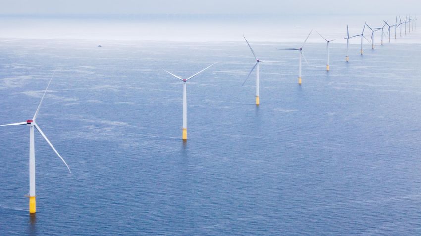
Offshore Wind
Submarine Cabling

        Duncan Sokolowski
        Senior Project Manager
        Tetra Tech

        May 26, 2021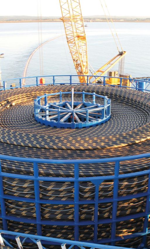
Meeting Procedures
Webinar recordings and presentations will be available at:
www.nyserda.ny.gov/osw-webinar-series

Participation for Members of the Public:
> Members of the public will be muted upon entry.

                                                               You'll see    when your
                                                               microphone is muted
> Questions and comments may be submitted in writing through
  the Q&A feature at any time during the event.

> If technical problems arise, please contact
  Sal.Graven@nyserda.ny.gov
Offshore Wind Submarine Power Cables – An
Introduction

Duncan Sokolowski – Sr Project Manager, Submarine Cable Services at Tetra Tech
Offshore Wind Submarine Cabling

The potential scale of the industry

The American Wind Energy Association estimates that by 2030, the USA
will have between 20,000 and 30,000 MW of installed offshore wind
power.

20,000 MW of offshore wind power will require approximately 1,650
turbines (of 12 MW each):-

•   Approximately 50 export cables (~3,000 miles)
•   2,000 inter array cables (~2,000 miles).
Offshore Wind Submarine Cabling
An overview of the cabling.

                                                    HVDC Cable ‘slices’
                                     Neptune project on the left, Basslink (Tasmania) on
                                                          the right
           HVAC Cable
Array Cable and Export Cable cross
             sections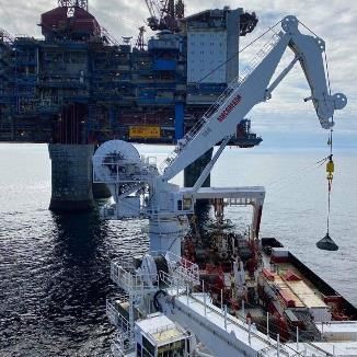
Offshore Wind Submarine Cabling
                  Parameter                  HVAC Arrays             HVAC Export                             HVDC
     Outer Diameter Range       4.25 in – 6.3 in           10 in – 13 in                     Approx. 6 in (150 mm) NOTE: Return
                                (110 mm – 160 mm)          (250 mm – 320 mm)                 cable is of smaller diameter

     Weight in Air              13 lbs/ft – 34 lbs/ft      Up to approx. 85 lbs/ft           Approx. 40 lbs/ft
                                (20 kg/m – 51 kg/m)        (125 kg/m)                        (60 kg/m) for entire bundle

     Conductor Cross-Section    3 x 120 mm2 –              3 x 800 mm2 –                     Up to approx. 1800 mm2
                                800 mm2                    1400 mm2
     Voltage Rating (approx.)   < 66 kV                    132 – 345 kV                      Up to approx. +/- 600 kV
     Electrical Losses                                     Medium (at the longest lengths)   Low

     Practical Maximum Length                              ~60-70miles (100-120km)           Theoretically unlimited, currently
                                                                                             the longest submarine HVDC cable is
                                                                                             720 km (450 miles) for North Sea
                                                                                             Link

     Max power per cable                                   ~400 MW                           Currently ~2,200MW for Western
                                                                                             Link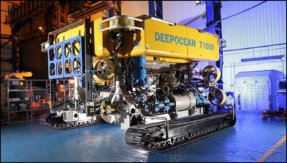
Offshore Wind Submarine Cabling
Impacts/Risks to and from Cabling
                     Party                                 Risk/Impact                                                Consequences
                                                                                                                     Loss of revenue
                 Cable Owner                              Cable damage                                          Cost of repair operation
                                                                                                             Increased insurance premiums
                                            Insurance claim either to cable owner or
                    Insurer                                                                       Insurance payout, future risks on other insured assets
                                         commercial/fishing vessel that impacts cable
                                      Possible legal liability if deemed to be at fault, vessel
                                                                                                             Commercial and legal impacts.
               Shipping Industry                            delays/arrest.
                                                                                                                    Health and Safety
                                                         Health and Safety
                                      Possible legal liability if deemed to be at fault, vessel
                                                            delays/arrest.                                   Commercial and legal impacts.
                Fishing Industry
                                                         Lost fishing gear                                          Health and Safety
                                                      Health and Safety
                 Grid Operator                   Generating source goes offline                        Consequential grid operational implications
                                                                                                           Changes to the permitting process
             Regulatory Authorities                 Processes and reputation
                                                                                                                    Public perception
                                                   Turbidity during installation
                 Environment                                    EMF
                                                          Heating effects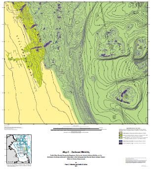
Offshore Wind Submarine Cabling
   Vineyard Wind Final Environmental Impact Statement – A Summary of Mitigation Measures
 Measure Number & name                                       Description                                                    Expected Effect on Impacts                          Authority
11 – Dredging & Cable
                                Requires cable installation activities to use the least environmentally   Will reduce the expected minor to moderate temporary impacts          MassDEP
Installation Methods &
                                  harmful method – also defines installation window restrictions                     on coastal habitats and benthic resources                 NMFS EFH
Timing
                                                                                                          Reduces the impact on the seafloor etc. Any applicable if anchor
12 – Anchoring Plan              Requires an anchoring plan in all areas where anchoring is planned                                                                              BOEM
                                                                                                                             barges etc are planned
14 – Final cable protection      Natural or engineered stone that mimics the surrounding seafloor,         Reduces the expected moderate impacts and improve possible          Mass CZM
in hard bottom                                       nature inclusive designs                                                    minor benefits                                  BOEM
                                A minimum of 75 benthic samples & 60 video transects to be taken
15 – Evaluation of benthic                                                                                Wouldn’t change the rating but would allow sensitive areas to be
                                 along the export cable corridor. Information to be used to update                                                                               BOEM
habitat prior to cable laying                                                                                                        avoided
                                                           habitat maps etc
                                     Export and IA cable surveys at years 1,2 and every 3 years              Wouldn’t affect the impacts on benthic resources but could
18 – Post-installation cable
                                thereafter, as well as after a ‘major storm event’. A DTS system also     reduce the impacts on commercial fisheries by detecting reduced        BOEM
monitoring
                                                                required.                                                               burial
74 – Providing electronic                                                                                  Would allow the fishing industry to make informed decisions re
                                    Make available information on the as-built location of cables                                                                            Voluntary by VW
charting information                                                                                                             fishing grounds etc
75, 76 & 77 –                   Create funds held in ESCROW to compensate the fishing industry for
                                                                                                                         Doesn’t change the impact rating                        Various
Compensation funds                                        direct impacts
80 – Submarine cable                 Location and burial depths of the entire cable system to be                                                                                  USCG
                                                                                                                To be reviewed by USCG & BOEM to aid planning etc
system burial plan                           submitted as a part of final documentation                                                                                          BOEM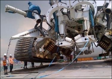
Offshore Wind Submarine Cabling
So how are submarine cables protected from external aggression, and how are external users
protected from cables? How are environmental impacts minimized?

1- Careful route planning, avoid as far as possible areas of high risk and environmental sensitivity.
Shipping lanes, anchorages, fishing grounds, steep slopes & hard seabeds, dumping sites & borrow
areas, areas of high seabed sediment mobility, other seabed assets (cables, pipelines etc), cultural
sites, eel grass and fish-spawning areas (for example) and more

2- Cable Burial. The deeper the cable is buried, the safer it is from external impact and the less
impact it will have on other users and the environment (except during installation)

3- Externally applied protection. Used where burial may be difficult or impossible such as areas of
bedrock or areas of reduced burial such as at crossings
Offshore Wind Submarine Cabling
Cable Burial is always the primary method of protection for cables.
What drives the specified or recommended cable burial depth?
•   Requirements from Federal and state agencies (e.g., USACE in federally maintained shipping channels
    requires 15’ depth below authorized, maintained channel depth)
•   Industry guidance from (for example) standards agency such as DNV GL, experience from
    organizations such as the North American Submarine Cable owners Association (NASCA) etc.
•   Risk appetite of asset owners/insurers/regulatory bodies (
There is a balancing act between too deep (expensive, environmental impacts, ampacity issues) and too
shallow (risk both to and from the cable).
So how is a recommended target burial depth derived?
Offshore Wind Submarine Cabling
Cable Burial Risk Assessment (CBRA)
A CBRA is a risk-based methodology used to determine the minimum recommended Depth Of
Lowering (DOL) for a submarine cable. The CBRA was developed by the U.K’s Carbon Trust which
commissioned a group of subject matter experts to create a method of determining risk to a
submarine cable system and therefore specify a DOL that will reduce risk ‘As Low As is Reasonably
Practicable’ (ALARP).
The CBRA will determine a minimum recommended DOL
(A) at each point along the cable route.
To achieve this, the installation contractor will select a
burial method to achieve a target DOL (B). This allows for a
slight margin of error in case of unexpected hard soils, for
example.
A target trench depth (C) will help to ensure that the
minimum DOL is attained by accounting for any potential
backfill.Offshore Wind Submarine Cabling What goes into a CBRA? Any external factor that can damage the cable, or in turn can be damaged by the cable is taken into consideration, these are a mix of natural and human (anthropogenic) factors. • Commercial vessel activity • Commercial (& recreational) fishing activity • Dumping areas Proper route planning will avoid • Dredging activity challenging geophysical conditions • Obstructions (wrecks etc.) (steep slopes, hard sediments etc.) as • Cultural sites well as areas of human activity where • UXO possible. Where this isn’t possible, the • Existing seabed assets CBRA will ensure that risk to the cable • Steep slopes, shoals, ravines, hard seafloor is reduced as far as is reasonably • Sediment mobility practicable • Wind, waves, tides, currents • Environmentally sensitive areas
Offshore Wind Submarine Cabling
What goes into a CBRA?

    Seabed Bathymetry    Sediment Mobility   Seabed Geology
Offshore Wind Submarine Cabling
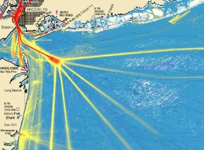
What goes into a CBRA?
Fishing Activity Analysis of fishing types &
(Hydraulic surf clam dredging, 2015 & 2016 VMS
Shipping Activity commercial vessel types
(2019 AIS Data, Mid-Atlantic Ocean Data Portal)
data) encounteredOffshore Wind Submarine Cabling
CBRA Output
Depth Of Lowering recommendations
Risk AssessmentOffshore Wind Submarine Cabling
When can cable installation commence?
The permitting of an offshore wind
farm is a process coordinated by
BOEM under the National
Environmental Policy Act (NEPA) of
1969.
Part of the permit requirements will
include installation windows that will
limit construction activities to times
that won’t impact migratory species,
fish spawning, etc.Offshore Wind Submarine Cabling
Cable Installation And Burial – Two common methods
Simultaneous Lay and Burial Post Lay Burial
The Cable Lay Vessel (CLV) lays and buries the cable in a The CLV lays the cable on the seabed, it is then buried
single operation. via a separate operation (usually by a different vessel).
Only one vessel required so saves on vessel day rates, Two vessels required but a lot of flexibility with regard to
however, the lay operations are a lot slower than if the making the full use out of weather windows.
cable is laid with no burial (surface lay). Therefore,
longer weather windows are required.Offshore Wind Submarine Cabling
Simultaneous Lay and Burial
Towed Plow Large Towed jetting sled
Towed jetting sled
~3m/10’ burial depth ~8m/25’ burial depth
~3m/10’ burial depth
15m long, 6.5m wide For shallower water, has optional chain cutter for harder
For shallower water & softer soils
Weighs approx. 50T soilsOffshore Wind Submarine Cabling
Simultaneous Lay and Burial
Vertical Injector Tracked Trencher Tracked Trencher
Up to 10m/33’ burial depth Deepoceans T3200 Van Oord’s ‘Deep Dig-It’
Deployed from a barge Weighs 170T, jetting and chain cutting up to 3.5m Weighs 125T, jetting and chain cutting up to 5.0m burial
Shallow water, softer soils burial depth depthOffshore Wind Submarine Cabling
Post Lay Burial
ROV ROV
ROV in ‘free-flying’ mode
Canyon’s T1200 Enshore’s T1000
For softer sediments where tracks would sink and cause a
Up to 3m/10’ burial depth Up to 3m/10’ burial depth
loss in maneuverability
Water jetting only Water jetting onlyOffshore Wind Submarine Cabling
Other burial techniques
Multimode plow can clear boulders (route clearance mode), cut a trench into which the cable is
Mass Flow Excavator (MFE) laid, then can backfill the trench after cable lay. Typically, can cut a ‘V’ or ‘Y’ shaped trench
between 1.0 and 2.0m in depth, depending upon soil conditionsOffshore Wind Submarine Cabling
Other Cable Protection
Rock Dumping Grout/Rock BagsOffshore Wind Submarine Cabling
Other Cable Protection
Concrete Mattresses Frond Matts/Nature Inclusive DesignsOffshore Wind Submarine Cabling
Other Cable Protection
Articulated Split Pipe Uraduct Cable Protection SystemsOffshore Wind Submarine Cabling
Cable Repairs
Cable joint being lifted out of jointing container Cable joint being deployed from vesselOffshore Wind Submarine Cabling
Cable Surveys
Cables are surveyed to ensure that the target depth of
lowering has been achieved (after burial) and at periodic
intervals to ensure that the cable isn’t becoming too
shallow or conversely, that the cable isn’t becoming too
deeply buried.
Cables that get shallower (mobile sediments move away
for example) are at risk of damage.
Cables that get deeper reduce the current carrying
capability due to the reduction in thermal conductivity.
How often?
It depends on site-specific conditions (e.g., how mobile the
seabed is) as well as regulatory permitting requirements.
It may be that initially, surveys are carried out every 1 to 2
years to establish baseline data, then the frequency can
be reduced once the cable burial depth trend is more
understood.Offshore Wind Submarine Cabling
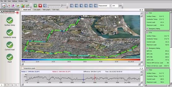
Cable Sensing
Distributed Temperature Sensing
• Equipment located in the control room &
offshore substation
• Utilizes one of the optical fibers
• Monitors the temperature at approximately 1 to
5m intervals along the cable
• Benefits?
• Cable can be operated closer to 90oC
(dynamic rating)
• Temperature trends monitored, data
analyzed to monitor depth of burial
• Strain sensing also possibleOffshore Wind Submarine Cabling
Cable Sensing
Distributed Vibration Sensing
• Equipment located in the control room &
offshore substation
• Utilizes one of the optical fibers
• Monitors the acoustics at 1m intervals along the
cable
• Benefits?
• Increased noise implies reduced burial
• Advance warning of anchoring, fishing etc
• Certain types of fault can be locatedOffshore Wind Submarine Cabling
Thank you, Any Questions?
Duncan Sokolowski
duncan.sokolowski@tetratech.comComing Next: June 9, 1:00 p.m. ET Digital Aerial Surveys to Inform Offshore Wind Development Julia Robinson Willmott, Normandeau Associates June 23, 1:00 p.m. ET We want your feedback! Send The Science of Visibility suggestions for future webinar topics Gordon Perkins & Kiva VanDerGeest, to offshorewind@nyserda.ny.gov. Environmental Design & Research Visit wind.ny.gov to register
You can also read