MECHANICAL MIRROR SANNA DAHLIN HENRIK FAGERLUND - DEGREE PROJECT IN MECHANICAL ENGINEERING, FIRST CYCLE, 15 CREDITS STOCKHOLM, SWEDEN 2021 - DIVA ...
←
→
Page content transcription
If your browser does not render page correctly, please read the page content below
DEGREE PROJECT IN MECHANICAL ENGINEERING,
FIRST CYCLE, 15 CREDITS
STOCKHOLM, SWEDEN 2021

Mechanical Mirror

SANNA DAHLIN

HENRIK FAGERLUND

KTH ROYAL INSTITUTE OF TECHNOLOGY
SCHOOL OF INDUSTRIAL ENGINEERING AND MANAGEMENT

Mechanical mirror

   SANNA DAHLIN
 HENRIK FAGERLUND

 Bachelor’s Thesis at ITM
 Supervisor: Nihad Subasic
 Examiner: Nihad Subasic

 TRITA-ITM-EX-2021-31
Abstract
This bachelor thesis aims to present an overview of the
performed steps to construct and program a prototype of a
mechanical mirror. The idea of a mechanical mirror is that
a camera captures an image that is translated into pixels
of different brightness values. The brightness values are
later displayed by metal plates, acting as pixels, rotated
to different angles to reflect a corresponding light from a
lamp. The pixels together shape grayscale images based on
the frames captured by the camera.
     A prototype was constructed successfully. Tests showed
that its purpose to move according to the captured image
was fulfilled although adjustments could be made for the
light to reach all the pixels to a greater extent. The angle
span for the pixels turned out to be between 32°and 44°,
which proved sufficient for their purpose. The reason for a
difference in angle spans between the pixels was due to mi-
nor construction errors and was not an issue of functionality
for the mirror.
     The refresh rate of the mirror, which could be described
as the frequency at which the pixels rotate and shape an
image, was set to 25 frames per second. This allowed the
mirror to mimic movements in front of it without much de-
lay while not exceeding the frame rate of the camera, which
capture at a frame rate of 30 frames per second. The cam-
era was therefore the vital limitation for the refresh rate of
the mirror.
Keywords— Mechatronics, Arduino, Prototype, Image pro-
cessing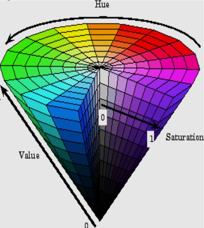
Referat
                    Mekanisk Spegel
Detta kanidatexamensarbete har syftet att presentera en
översikt av de steg som genomfördes för att konstruera och
programmera en prototyp av en mekanisk spegel. Idén med
en mekanisk spegel är att en kamera läser in en bild som
sedan är översatt till pixlar med olika värden på ljusstyrka.
Dessa ljusstyrkor visas sedan av metallplattor, vilka agerar
som pixlar, som roterar till olika vinklar för att reflektera
motsvarande ljus från en lampa. Pixlarna formar tillsam-
mans gråskalebilder baserat på de bilder som kameran läser
in.
     En prototyp konstruerades framgångsrikt. Test visade
att dess syfte att röra sig i enlighet med den inlästa bilden
uppfylldes, dock finns plats för justeringar för att ljuset
från lampan ska nå pixlarna i större utsträckning. Pixlar-
nas vinkelomfång visade sig bli mellan 32°och 44°, vilket
konstaterades vara tillräckligt för deras syfte. Skillnaden i
vinkelomfång mellan pixlarna berodde på mindre konstruk-
tionsfel och påverkade inte spegels funktionalitet.
     Spegelns uppdateringsfrekvens, vilket kan beskrivas som
frekvensen med vilken pixlarna roterar och formar en bild,
sattes till 25 bilder per sekund. Detta tillät spegeln att
härma rörelser framför den utan stor fördröjning utan att
överstiga kamerans bildhastighet, som läser in med en bild-
hastighet på 30 bilder per sekund. Kameran var således den
begränsade faktorn för pixlarnas uppdateringsfrekvens.
Nyckelord— Mekatronik, Arduino, Prototyp, Bildbehand-
ling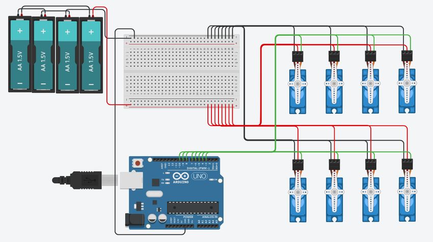
Acknowledgements

We would like to thank the course supervisor Nihad Subasic. We would also like to
show gratitude towards Staffan Qvarnström who helped with all things regarding
soldering and ordering of parts. A special thanks to Tomas Östberg who made the
construction of the pixels possible. Lastly, we would like to thank Amir Avdic who
was at hand to answer questions during the project.

                                              Sanna Dahlin and Henrik Fagerlund
                                                           Stockholm, May, 2021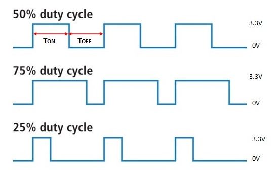
Contents

1 Introduction                                                                                                                                       1
  1.1 Background     .   .   .   .   .   .   .   .   .   .   .   .   .   .   .   .   .   .   .   .   .   .   .   .   .   .   .   .   .   .   .   .   1
  1.2 Purpose . .    .   .   .   .   .   .   .   .   .   .   .   .   .   .   .   .   .   .   .   .   .   .   .   .   .   .   .   .   .   .   .   .   2
  1.3 Scope . . .    .   .   .   .   .   .   .   .   .   .   .   .   .   .   .   .   .   .   .   .   .   .   .   .   .   .   .   .   .   .   .   .   2
  1.4 Method . .     .   .   .   .   .   .   .   .   .   .   .   .   .   .   .   .   .   .   .   .   .   .   .   .   .   .   .   .   .   .   .   .   2

2 Theory                                                                                                                                              3
  2.1 Law of reflection . . . .                  .   .   .   .   .   .   .   .   .   .   .   .   .   .   .   .   .   .   .   .   .   .   .   .   .    3
  2.2 Microcontroller . . . . .                  .   .   .   .   .   .   .   .   .   .   .   .   .   .   .   .   .   .   .   .   .   .   .   .   .    4
  2.3 OpenCV . . . . . . . . .                   .   .   .   .   .   .   .   .   .   .   .   .   .   .   .   .   .   .   .   .   .   .   .   .   .    4
  2.4 HSV . . . . . . . . . . .                  .   .   .   .   .   .   .   .   .   .   .   .   .   .   .   .   .   .   .   .   .   .   .   .   .    4
  2.5 pySerial . . . . . . . . .                 .   .   .   .   .   .   .   .   .   .   .   .   .   .   .   .   .   .   .   .   .   .   .   .   .    5
  2.6 Micro servo . . . . . . .                  .   .   .   .   .   .   .   .   .   .   .   .   .   .   .   .   .   .   .   .   .   .   .   .   .    5
  2.7 Pulse Width Modulation                     .   .   .   .   .   .   .   .   .   .   .   .   .   .   .   .   .   .   .   .   .   .   .   .   .    5
  2.8 Computer Aided Design                      .   .   .   .   .   .   .   .   .   .   .   .   .   .   .   .   .   .   .   .   .   .   .   .   .    6
  2.9 3D printing . . . . . . .                  .   .   .   .   .   .   .   .   .   .   .   .   .   .   .   .   .   .   .   .   .   .   .   .   .    6

3 Demonstrator                                                                                                                                        7
  3.1 Hardware . . . . . . . .                   .   .   .   .   .   .   .   .   .   .   .   .   .   .   .   .   .   .   .   .   .   .   .   .   .    8
      3.1.1 Arduino . . . . .                    .   .   .   .   .   .   .   .   .   .   .   .   .   .   .   .   .   .   .   .   .   .   .   .   .    8
      3.1.2 Micro servos . .                     .   .   .   .   .   .   .   .   .   .   .   .   .   .   .   .   .   .   .   .   .   .   .   .   .    9
  3.2 Software . . . . . . . . .                 .   .   .   .   .   .   .   .   .   .   .   .   .   .   .   .   .   .   .   .   .   .   .   .   .    9
      3.2.1 Image processing                     .   .   .   .   .   .   .   .   .   .   .   .   .   .   .   .   .   .   .   .   .   .   .   .   .    9
      3.2.2 Servo control . .                    .   .   .   .   .   .   .   .   .   .   .   .   .   .   .   .   .   .   .   .   .   .   .   .   .   11
  3.3 Carrier construction . .                   .   .   .   .   .   .   .   .   .   .   .   .   .   .   .   .   .   .   .   .   .   .   .   .   .   11
  3.4 Camera . . . . . . . . .                   .   .   .   .   .   .   .   .   .   .   .   .   .   .   .   .   .   .   .   .   .   .   .   .   .   12
  3.5 Light source . . . . . . .                 .   .   .   .   .   .   .   .   .   .   .   .   .   .   .   .   .   .   .   .   .   .   .   .   .   12
  3.6 Pixels . . . . . . . . . .                 .   .   .   .   .   .   .   .   .   .   .   .   .   .   .   .   .   .   .   .   .   .   .   .   .   13

4 Results                                                                                                                                            15

5 Discussion and conclusion                                                                                                                          17

6 Recommendations and future work                                                                                                                    19
CONTENTS Bibliography 21 Appendices 22 A Python code 23 B Arduino code 25 C Micro servo MS-1.3-9 datasheet 29 D Micro servo Tower Pro SG90 datasheet 31 E Acumen code 33
List of Figures

2.1   Illustrating the angle of incidence (i) and angle of reflection   (r)   [6].   .   .   .   3
2.2   Diagram of color mix in HSV-format [11]. . . . . . . . . . .      . .   . .    .   .   .   4
2.3   Schematic of feedback-loop in servo motor [14]. . . . . . . .     . .   . .    .   .   .   5
2.4   Description of the PWM-signal [7]. . . . . . . . . . . . . . .    . .   . .    .   .   .   6

3.1  The final construction (taken by authors). . . . . . . . . . . . . . . . . .                 7
3.2  Wiring diagram of the circuit (made with Autodesk Tinkercad) [5]. . . .                      8
3.3  Frame read by the camera (taken by authors). . . . . . . . . . . . . . .                    10
3.4  Flipped frame (taken by authors). . . . . . . . . . . . . . . . . . . . . .                 10
3.5  Resized frame in grayscale (taken by authors). . . . . . . . . . . . . . .                  10
3.6  The back of the carrier construction with components (taken by authors).                    12
3.7  The two holders for the lamp fastened in the carrier (made with Solid
     Edge) [19]. . . . . . . . . . . . . . . . . . . . . . . . . . . . . . . . . . .             13
3.8 The different parts of the pixel (made with Solid Edge) [19]. . . . . . . .                  13
3.9 The two parts of the link (made with Solid Edge) [19]. . . . . . . . . . .                   14
3.10 Angle relationship (made with Apple Inc. Keynote) [13]. . . . . . . . . .                   14
List of Tables 3.1 Servo specifications, Appendix D and Appendix C. . . . . . . . . . . . . 9
List of Abbreviations

3D - Three dimensional
CAD - Computer-Aided Design
COM - Communication
DC - Direct Current
FPS - Frames Per Second
HSV - Hue, Saturation, Value
IDE - Integrated Development Environment
KTH - Royal Institute of Technology
LED - Light Emitting Diode
OpenCV - Open Source Computer Vision Library
PLA - Polylactic acid
PWM - Pulse Width Modulation
RGB - Red, Green, Blue
USB - Universal Serial Bus
Nomenclature

A - Ampere
MHz - Megahertz lm - Lumen
mA - Milliampere
ms - Milliseconds
SEK - Swedish Krona
V - Volt
Chapter 1

Introduction

This thesis is about constructing a mechanical mirror. The idea of a mechanical
mirror is a moving construction with the purpose of mirroring the physical move-
ments captured by a camera. The construction is a form of display with numerous
mechanical pixels that rotate at different angles and together creates an image. The
reason for choosing this project was because of the interest to capture human inter-
action and mimic this through data manipulation. To construct something with a
design aspect was also desirable.
    The project can be broken down into three main problems:

  1. Construction: constructing a prototype.

  2. Image processing: convert a digital image to mechanical movement.

  3. Servo control: control the servo motors as desired.

1.1    Background
The general idea for the project came from the work of Israel-American artist Daniel
Razin who has created mechanical mirrors with several different designs as an art
project [10]. Mirrors are often featured in art projects around the world. This
could be because of the human fascination to interact with art. To mimic the
human motion in a mechanical mirror Daniel Razin uses single pixels driven by
stepper motors and a camera to capture the image in front of the mirror. This
project follows a similar basic construction, with original solutions applied.

                                         1
2 CHAPTER 1. INTRODUCTION
1.2 Purpose
The purpose of this bachelor thesis was to construct a mechanical mirror and to
discuss the following research questions:
- What are the vital limitations for the refresh rate of the mirror, allowing an
accurate imitation of the captured image?
- What sort of construction can be made to favour a large rotational interval for
the pixels?
1.3 Scope
This project was managed by KTH Royal Institute of Technology and therefore also
faced limitations set by the university. The time frame for the project was around
five months and the budget was 1000 SEK. The scope of the project was therefore
limited to creating a smaller prototype of the idea with a small quantity of pixels.
The worldwide pandemic also made access to equipment and school workshops more
circumstantial.
1.4 Method
To start off the project, a literature study was conducted in order to gather infor-
mation to answer the research questions later on and also to get an insight on the
subject. Once the literature study was completed the rest of the project involved;
construction of a prototype, programming a working software and answering the
research questions. The construction of the prototype and the programming were
performed simultaneously whereas the research questions were answered later dur-
ing the project.
The finished prototype was tested to determine the performance of the con-
struction. The results were then discussed and concluded, and future work was
proposed.Chapter 2
Theory
The following theory worked as a base not only to answer the research questions
but also for the constructing and programming of the prototype.
2.1 Law of reflection
The following figure, Figure 2.1, illustrates the behaviour of light reflecting on a flat
surface. The angle of which the incident ray (labeled A in the figure) respectively
the reflecting ray (labeled B in the figure) makes with the normal to the reflector
(labeled N in the figure) is called angle of incidence respectively angle of reflection
and marked i respectively r in the figure. The law of reflection states that the angle
of incidence is equal to the angle of reflection [6].
Figure 2.1. Illustrating the angle of incidence (i) and angle of reflection (r) [6].
34 CHAPTER 2. THEORY
2.2 Microcontroller
A microcontroller board can be described as a command center that is commanded
through lines of codes. Through wires the board is then connected in one way or
another to what is being controlled. The board could for instance be turning a light
on or off or reading a sensor value and returning it to the computer. The speed of
which a line of code transfers into an action is determined by the efficiency of the
code, the speed of the circuit and the clock speed. The clock speed is a measurement
for the speed of the microcontroller board in itself [20].
2.3 OpenCV
Open Source Computer Vision Library (OpenCV) is a library built on the program-
ming language C and C++. OpenCV provides a computer vision infrastructure
and contains over 500 functions in areas such as factory product inspection, medi-
cal imaging, security, user interface, camera calibration, stereo vision, and robotics.
The functions in this library can consequently be used for transitioning images
captured by a camera into data [8].
2.4 HSV
HSV (Hue, Saturation, Value) is a color model for describing a color in code. A
diagram of the model is shown in Figure 2.2. Instead of describing a color in
red, green and blue (RGB), HSV defines a color in three different dimensions: hue
(rotational angle in diagram), saturation (radius value in diagram) and value (height
value in diagram). The value (’V’) in HSV represents the brightness of the color
[18].
Figure 2.2. Diagram of color mix in HSV-format [11].2.5. PYSERIAL 5
2.5 pySerial
pySerial is a module that enables access to serial ports through Python proper-
ties. That is, what is calculated with Python can be written on the serial COM
port that the microcontroller board is on and then read for the microcontroller to
execute. This way the module enables communication between Python and the
microcontroller board [15].
2.6 Micro servo
A micro servo is a smaller and lighter type of servo motor. A servo motor contains
four core components which together creates a closed feedback-loop: DC-motor,
gearbox, control circuit and a feedback mechanism in form of a potentiometer. The
potentiometer is attached to the output shaft of the gearbox and sending information
about the position to the control circuit. The control circuit controls the DC-motor
and creates, through a gearbox, rotation on the output shaft. The servo motor can
through this method tell with high accuracy how many degrees the motor shaft has
rotated [1]. The feedback system is demonstrated in Figure 2.3.
Figure 2.3. Schematic of feedback-loop in servo motor [14].
2.7 Pulse Width Modulation
A microcontroller board has different kinds of inputs and outputs: analog and dig-
ital. With the use of software, the digital outputs can also be programmed to work
as so-called PWM outputs. The term PWM stands for Pulse Width Modulation
and what specifies these outputs is the ability to control a unit more carefully than
with just binary control [16]. For example, to dim the light of a LED light from
low to high instead of just directly switching it from low to high, the use of PWM
is necessary.6 CHAPTER 2. THEORY
The way PWM works is by sending an analog signal from a digital output.
Analog signals are desirable continuous signals whereas digital signals are time sep-
arate binary signals. Starting from a digital output and altering the duration of
”High-time” (also known as pulse width), an analog signal is created. The result
is a steady signal between low voltage and high voltage depending on the so called
duty cycle, which is the percentage of ”High-time” during a period, see Figure 2.4,
[16].
Figure 2.4. Description of the PWM-signal [7].
2.8 Computer Aided Design
Computer Aided Design (CAD) refers to assisting the design process in any industry
through a computer. The most common way to use CAD software is to create three-
dimensional (3D) models on the computer, thus visualizing and specifying a model
of a construction without having manufactured it yet [2].
2.9 3D printing
3D printing is a way to print a model made with CAD into a real life model. The
way a 3D printer works is by melting PLA plastic with a nozzle, that layer by layer
creates the model from the bottom up until completed. The manufacturing process
is an efficient way to ensure that the measurements from the CAD model will be
precise [9].Chapter 3
Demonstrator
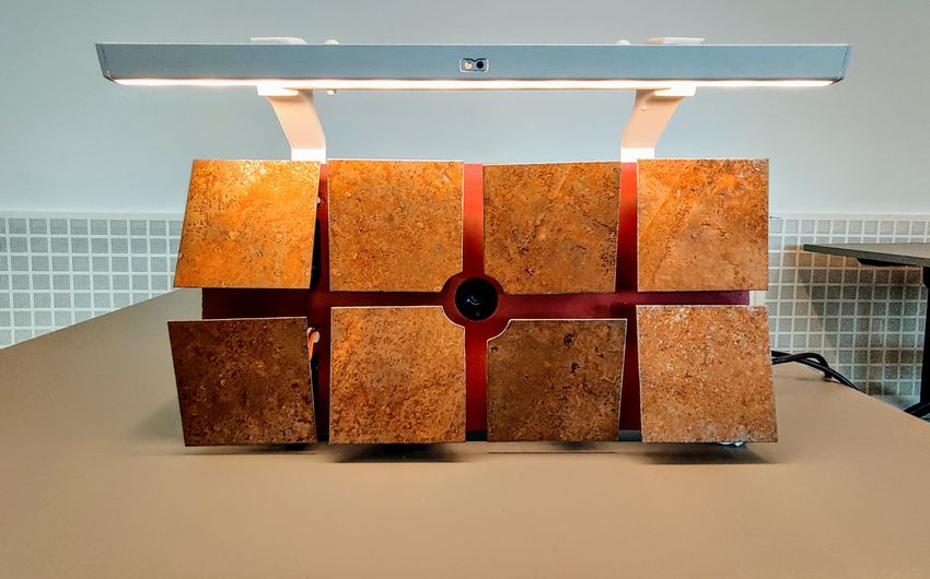
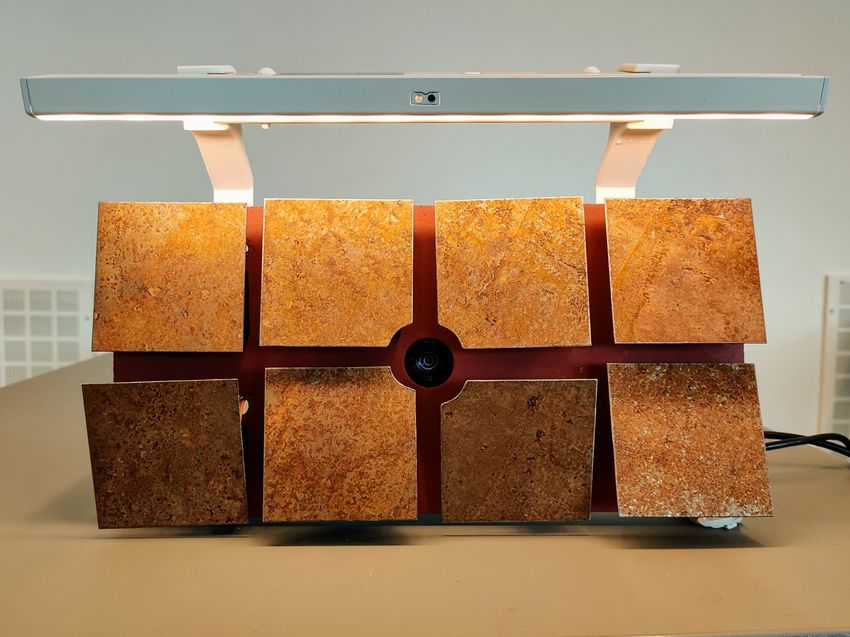
The final construction consists of a carrier construction that holds a camera, a
lamp and eight so-called pixels which are individually controlled by micro servos,
see Figure 3.1. The image, captured by the camera lens in the middle of the mirror,
is translated through data manipulation into rotational movement of the pixels.
The pixels then reflect different amounts of light based on the image, thus creating
a mirroring effect in grayscale.
Figure 3.1. The final construction (taken by authors).
The following chapter is a detailed overview of the prototype created, including
both the construction and software work.
78 CHAPTER 3. DEMONSTRATOR
3.1 Hardware
The circuit of the construction consists of a microcontroller board that, with an
additional power supply, controls the angle of the eight micro servos individually,
see Figure 3.2.
Figure 3.2. Wiring diagram of the circuit (made with Autodesk Tinkercad) [5].
3.1.1 Arduino
The microcontroller board used in this project was an Arduino Uno R3. The Ar-
duino Uno is based on the ATmega328P chip and has a clock speed of 16MHz. It
has 6 analog inputs and 14 digital input/output pins [4]. The code was written in
Arduino IDE with built-in libraries and the language used in the program is based
on C++.
The Arduino servo library uses software PWM signals which is required for
controlling a servo motor. This implies that the digital pins on the Arduino Uno
can be used to control servo motors. Hence, the Arduino Uno by itself allows
individual control of up to twelve servo motors and therefore satisfy this project’s
need for individual control of eight servo motors.3.2. SOFTWARE 9
3.1.2 Micro servos
The models of micro servos that were used are SG90 and MS-1.3-9. The two models
of micro servos operate with the same purpose and the specifications of the two
different models are relatively similar and are shown in Table 3.1.
Table 3.1. Servo specifications, Appendix D and Appendix C.
Servo model SG90 MS-1.3-9
Weight: 9 gram unknown
Operating voltage: 4.8V∼ 6V 4.8V∼ 6V
Operating angle: 180° 120°
Operating speed 0.12 sec/60° 0.12 sec/60°
(4.8V):
Operating speed 0.11 sec/60° 0.10 sec/60°
(6V):
Stall torque: 1.6 kg/cm (6V) 1.3kg/cm (4.8V)
Each micro servo has an operating voltage around 4.8 V∼ 6 V, see Table 3.1,
which means that the power supply needs to provide a voltage in that interval. A
battery holder containing four 1,5 V batteries was added to the circuit to satisfy
the demands and maximize the performance of the micro servos.
The current drawn from the micro servos is proportional to the working torque.
Because of the relatively small load, the micro servos operate on low torque and the
current provided by the four batteries is therefore more than enough for the circuit
to function properly [17].
3.2 Software
The software carries out the process to resize an image into eight pixels and change
the angle of the micro servos accordingly, making each individual pixel slant upward
and therefore reflect more light from the lamp or downward, making it reflect less.
The process can be divided into two sections: image processing and servo control,
all of which is looped for each new frame.
3.2.1 Image processing
Each frame captured by the camera is processed, individually and directly, through
six steps as shown below. The code is written in Python, see Appendix A.
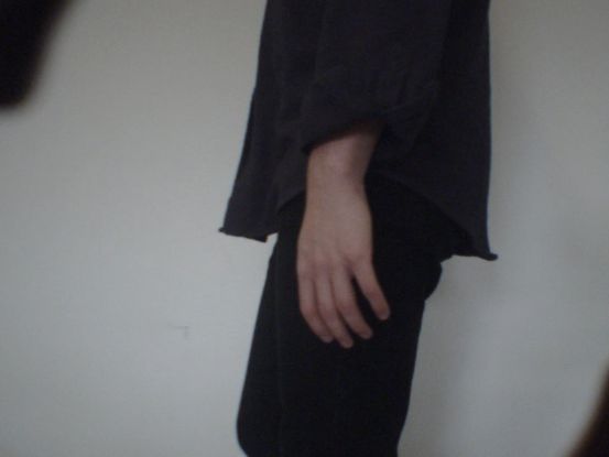
1. The frame is captured by the camera and read using the built-in function from
OpenCV library: read(), see Figure 3.3.10 CHAPTER 3. DEMONSTRATOR
Figure 3.3. Frame read by the camera (taken by authors).
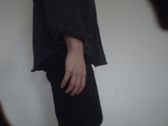
2. The frame is flipped horizontally to create a mirroring effect using the built-in
function from OpenCV library: flip(), see Figure 3.4.
Figure 3.4. Flipped frame (taken by authors).
3. The frame is resized to desired size using the built-in function from OpenCV
library: resize(), see Figure 3.5.
4. The image format is converted from RGB to HSV using the built-in func-
tion from OpenCV library: cvtColor(). Figure 3.5 shows a resized frame in
grayscale (ignoring hue and saturation), which represent what the constructed
mirror is supposed to mimic.
Figure 3.5. Resized frame in grayscale (taken by authors).3.3. CARRIER CONSTRUCTION 11
5. All of the pixel’s brightness-values (φrow column , ”V” in ”HSV”) are merged to
a string and separated with ”:”. The format of the string is shown in equation
3.1.
string = ”φ00 : φ01 : φ02 : φ03 : φ10 : φ11 : φ12 : φ13 ” (3.1)
6. The string is written on the same serial port that Arduino is on, using the
serial-library function: write(). This is done with help of the pySerial module.
3.2.2 Servo control
The servo motors are controlled by the Arduino Uno through code written in Ar-
duino IDE, see Appendix B. The servos are controlled through four steps:
1. The string is read and stored through Arduino’s serial port.
2. Each brightness value (interval: 0 - 255) is one by one taken out from the
string and converted into an angle of rotation (interval: αmin - αmax ). Each
pixel has its own minimum and maximum angle that were set through testing.
This is done for each separate pixel using equation 3.2.
αmax − αmin
αrow column = · φrow column + αmin (3.2)
255
3. The matching micro servo is written to the computed angle.
4. A time delay is added to achieve desired frame rate.
3.3 Carrier construction
The carrier construction is a wooden board that is designed to hold all other compo-
nents. The back of the board holds the wires and camera and is therefore equipped
with 3D printed legs to keep the circuit and camera from reaching the wall. The
cords from the micro servos pass through smaller holes along the board and the
camera lens see through the carrier through a larger hole in the middle, see Figure
3.6.12 CHAPTER 3. DEMONSTRATOR
Figure 3.6. The back of the carrier construction with components (taken by au-
thors).
3.4 Camera
The camera captures the image that is sent to the computer for processing. It
was placed in the middle of the construction to mimic the feel of a real mirror as
effectively as possible. The camera used in the project is a Sony PlayStation Eye
camera [3]. The camera was placed on a platform at the back of the carrier, see
Figure 3.6.
3.5 Light source
A lamp was placed at the top of the construction causing the light to hit the pixels
from above, see Figure 3.1. This creates a large contrast between light and dark,
depending on the angle of incidence that the light from the lamp creates with the
pixels. The lamp used is a battery driven LED list with a brightness of 50 lm
[12]. Two plastic holders for the lamp were constructed in CAD and 3D-printed,
see Figure 3.7. The holders were screwed into the back of the board.3.6. PIXELS 13
Figure 3.7. The two holders for the lamp fastened in the carrier (made with Solid
Edge) [19].
3.6 Pixels
One pixel consists of a quadratic metal plate and a micro servo connected through
a constructed link. The micro servo is also attached to a holder to easily fasten it
to the carrier, see Figure 3.8. Every part of the pixel was to be constructed in a
quantity of eight, except for the micro servos that were purchased.
Figure 3.8. The different parts of the pixel (made with Solid Edge) [19].
The visible part of the pixel is the metal plate. Its purpose is to reflect the
desired light from the lamp in an efficient yet aesthetic way. The choice of material
depended on the material’s weight and surface. A lightweight sheet metal was
chosen in order to facilitate the workload for the micro servos and for its design
properties.
A link connects the metal plate to the micro servo. The link consists of two
parts: a shaft and a mounting surface, see Figure 3.9.14 CHAPTER 3. DEMONSTRATOR
Figure 3.9. The two parts of the link (made with Solid Edge) [19].
The shaft, which was made from complementary plastic parts from the pur-
chased micro servos, was constructed to be as short as possible to minimize the
radius of the arc which the plate moves in, but still long enough to prevent the
plate from hitting the micro servo, see Figure 3.10. All the while enabling rotation
large enough to reflect the desired light.
Figure 3.10. Angle relationship (made with Apple Inc. Keynote) [13].
The mounting surface was created in CAD and 3D printed in plastic. Its purpose
is to ensure a more durable fastening between the shaft and the metal plate through
a larger surface. It was fastened to the metal plate with double sided tape.
A holder for the micro servo was made to facilitate the attachment of the micro
servo to the carrier construction, see Figure 3.8. The micro servo is screwed into
the holder, which is then screwed into the board. This solution also favours easy
repairs and exchanges of components.Chapter 4
Results
The performance of the prototype was a success. The camera was able to capture
an image, preferably against a monochrome background to get sharper contours
of the moving objects, and the pixels moved accordingly with a slight delay. The
light source reached all pixels well enough to fulfil their function of reflecting light
although the bottom row was sometimes slightly shadowed by the pixels on the top
row.
A test was conducted to test the servo motors’ ability to react with different
time delays. The servo motors reacted well with all delays higher than around 33
ms. Under the 33 ms limit the movements of the pixels seemed to create an image
less accurate to reality. The servos reacted more often than they should, creating
duplicates of frames in a way that appeared shaky. The time set for the delay
was therefore 40 ms, which proved through testing to be the most optimal delay to
achieve a fast reaction but without going under the 33 ms limit. This mean that
the mirror operated at a frame rate of 25 FPS (frames per second).
The angle span for the pixels ended up being between 32°and 44°. The reason
for the spans to differ between pixels is because of minor construction errors when
assembling each pixel, the differences were however not visible to the eye. The pixels
were able to reflect a large amount of light at their maximum state and small to
no amount of light at their minimum state from the light source. The angle spans
were therefore sufficient to fulfil their purpose.
15Chapter 5
Discussion and conclusion
The reason for the servos to malfunction under the 33 ms limit is discussed to
be because the camera only captures 30 FPS. This means that there is only one
frame to be processed every 33 ms and therefore a delay smaller than that makes
the servos react on the same frame more than once. This implies that the camera
is the decisive factor for maximizing the refresh rate, which answers the research
question ”What are the vital limitations for the refresh rate of the mirror, allowing
an accurate imitation of the captured image?”. If this were not the case, the vital
factor would most likely be the speed of the servos. Because if the delay would be
too small the micro servos would not be able to get to their assigned angle until the
next assigned angle would be put into effect. That way the pixels would not always
reach their goal of angle and would not portrait an accurate picture of reality.
The construction of the pixels, as mentioned, granted a sufficient angle span
which answers the question ”What sort of construction can be made to favour a
large rotational interval for the pixels?”. What limited the angle span for the pixels
was the collision with the micro servos. To allow a larger angle span the link of
the pixel would have to be longer. This would on the other hand create a larger
area of which the metal plate would occupy when moving and enlarge the distance
between the plates. Both cases were in consideration during the construction and
the final solution is a compromise that satisfies the demands of the angle span but
also allows a reasonable distance between the pixels. The option to create a solution
where the pixels rotated around their own center point was ruled out because of the
complexity it would bring to the construction.
A different solution for the light source would be considerable to reach the pixels
on the lower row of the mirror better. Because the upper row slightly shadows the
lower row, a better solution might be to have a smaller LED list attached above
each row to create an even flow of light to all pixels.
In conclusion the prototype managed to fulfil its purpose to a high degree. The
alterations that could improve the construction would be to explore the idea of a
different light source and to change the camera to one able to capture an increased
number of frames per second.
17Chapter 6
Recommendations and future work
Because of the fact that the prototype only consist of eight pixels it was difficult
to distinguish clear mirrored images. To further develop the concept in the future,
a desirable goal is to expand the magnitude of pixels which would create a closer
mirroring of the details of the captured image. An expansion in size would need
a more complex circuit, especially because of the need to add a large quantity of
PWM outlets for all the servo motors. With a larger amount of pixels, a different
solution for the light source would be even more vital in order to distribute the light
on all pixels.
The software is constructed to work for any number of pixels and can therefore
easily be adapted for a larger number of pixels. For an immense number of pixels
there could eventually have to be some changes done in the software to ensure
that the pixels rotate simultaneously. Apart from that, further development would
almost exclusively involve working with the physical construction.
19Bibliography
[1] J. Abrahamsson, J. Danmo, Degree Project in Technicalogy: The Sta-
bilazing Spoon: Self-stabilizing utensil to help people with impaired
motor skills, http://kth.diva-portal.org/smash/get/diva2:1200521/
FULLTEXT01.pdf, Stockholm: KTH, 2017.
[2] All3Dprint, What is CAD?, https://all3dp.com/2/
what-is-cad-design-simply-explained/, Online; accessed 2021-05-05
[3] Amazon, Sony PlayStaion Eye, https://www.amazon.com/
Sony-PlayStation-Camera-Bulk-Packaging-Pc/dp/B0072I2240, On-
line; accessed 2021-05-05.
[4] Arduino Store, Arduino Uno REV3, https://store.arduino.cc/
arduino-uno-rev3, Online; accessed 2021-02-15, 2021.
[5] Autodesk Tinkercad, Tinkercad, https://www.tinkercad.com, Online; ac-
cessed 2021-05-05.
[6] P.R. Bhattacharjee, The generalized vectorial laws of reflection and refraction,
Agartala: Eur. J. Phys. 26, 2005.
[7] Binary Updates, PWM Duty Cycle Pulse, https://binaryupdates.com/
pwm-in-lpc2148-arm7/pwm-duty-cycle-pulse/, Online; accessed 2021-04-
08.
[8] G. Bradski, A. Kaehler, Learning OpenCV: Computer Vision with the
OpenCV Library, Sebastopol: O´Reilly Media Inc, 2008.
[9] Built in, Introduction to 3D printing, https://builtin.com/3d-printing,
Online; accessed 2021-05-05.
[10] Digicult, Daniel Rozin mirror of the soul, http://digicult.it/design/
daniel-rozin-mirror-of-the-soul/, Online; accessed 2021-05-05.
[11] N.A. Ibraheem, M.M. Hasan, R.Z. Khan, P.K. Mishra, Understanding Color
Models: A Review, Uttar Paradesh: ARPN Journal of Science and Technology,
2012.
2122 BIBLIOGRAPHY
[12] IKEA, Stötta LED ljuslist, https://www.ikea.com/se/sv/p/
stoetta-led-ljuslist-foer-skap-med-sensor-batteridriven-vit-10360087/,
Online; accessed 2021-05-05.
[13] Keynote, 2021, Apple Inc., Accessed: 2021-04-20, Presentation software.
[14] learn.adafruit.com, About Servos and Feedback, https://learn.adafruit.
com/analog-feedback-servos/about-servos-and-feedback, Online; ac-
cessed 2021-04-11, 2021.
[15] C. Liechti, pySerial Documentation, https://readthedocs.org/projects/
pyserial/downloads/pdf/latest/, 2018, Online; accessed 2021-05-07
[16] E.O Ljudén, Degree Project in Technology: Autonomous Hover Control Sys-
tem for a Radio-Controlled Aerobatic Airplane, http://www.diva-portal.
org/smash/get/diva2:1217474/FULLTEXT01.pdf, Stockholm: KTH, 2018.
[17] Ohio Electronic Motors, What is electrical torque and mechan-
ical torque?, https://www.ohioelectricmotors.com/2015/07/
what-is-electrical-torque-and-mechanical-torque/, Online; accessed
2021-05-05.
[18] Programming Design Systems, Color models and color
spaces, https://programmingdesignsystems.com/color/
color-models-and-color-spaces/index.html, Online; accessed 2021-
04-11, 2021.
[19] Solid Edge, 2020, Siemens, Accessed: 2021-05-07, CAD software.
[20] J.D. Warren, J. Adams, H. Molle, Arduino for Robotics, Berkeley: Apress,
2011.Appendix A
Python code
# Bachelor’s Thesis in Mechatronics VT21
# MF133XVT211
# Group 13 - Sanna Dahlin och Henrik Fagerlund
# 2021-05-08
# Image processing with Python
import serial
import time
import cv2
from PIL import ImageGrab
import numpy as np
arduino = serial.Serial(port=’COM5’, baudrate=115200, timeout=.1)
time.sleep(1) # give the connection a second to settle
# ------ camera drivers not working ------
# cap = cv2.VideoCapture(0)
while(True):
# ------ 1. Read each frame ------
# A specific part of the computer frame is captured
imgread = ImageGrab.grab(bbox=(62,104,650,533)) #bbox specifies
specific region (bbox= x,y,width,height)
img = np.array(imgread)
# ------ 2. Flip each frame for it to mirror ------
img = cv2.flip(img, 1)
# ------ visual -------
img_gray = cv2.cvtColor(img, cv2.COLOR_BGR2GRAY)
2324 APPENDIX A. PYTHON CODE
full_height, full_width = img.shape[:2] # get full height and width
for resizing and use for visual representation
# ------ 3. Resize frame to desired size ------
desired_height, desired_width = (2, 4) # set desired height and width
(number of pixels)
img = cv2.resize(img, (desired_width, desired_height),
interpolation=cv2.INTER_LINEAR) # create resized image in the
desired size
# ------ visual -------
pixel_big = cv2.resize(img, (full_width, full_height),
interpolation=cv2.INTER_NEAREST) # show full window
pixel_gray = cv2.cvtColor(pixel_big, cv2.COLOR_BGR2GRAY) # grayscale,
for better representation of the mirror
cv2.imshow(’img’, img_gray)
cv2.imshow(’img2’, pixel_gray)
# ------ 4. Convert BGR (Blue, Green, Red) to HSV-format (Hue,
Saturation, Value) ------
img = cv2.cvtColor(img, cv2.COLOR_BGR2HSV)
# ------ 5. Merge each pixels brightness-value to a String,
frameValues ------
frameValues = ""
for j in range(0, desired_height): # for every "row"
for i in range(0, desired_width): # for every "column"
frameValues += str(round(img[j,i,2])) # add to String (array)
if not (j == (desired_height-1) and i == (desired_width-1)): #
separate each servo-value with ":"
frameValues += ":"
# ------ 6. Send all values to arduino, string with format:
(XX:XX:XX:XX:XX:XX:XX:XX) ------
arduino.write(bytes(frameValues, ’utf-8’))
k = cv2.waitKey(10) & 0xFF
if k == 27: # ESC to break program
break
cv2.destroyAllWindows()Appendix B
Arduino code
// Bachelor’s Thesis in Mechatronics VT21
// MF133XVT211
// Group 13 - Sanna Dahlin och Henrik Fagerlund
// 2021-05-08
// Servo control by Arduino
#include
Servo servo[8];
int width = 4; // number of pixels in width
int height = 2; // number of pixels in height
int minPos[8] = {74, 76, 75, 84, 92, 80, 100, 98};
int maxPos[8] = {114, 108, 119, 50, 133, 122, 60, 60};
int midPos[8] = {90, 91, 92, 69, 107, 95, 85, 84};
int maxVal = 255; // maximum brightness-value (HSV)
int minVal = 80; // minimum brightness-value (HSV) (mirror does not show
darker than this value)
String val; // read from serial
String pixelValue; // value for each pixel
int value; // value for each pixel as int
int posRet; // returning position from valToPos
int pos; // position for each servo
int arr[8];
String returnArray = "";
void setup() {
Serial.begin(115200);
2526 APPENDIX B. ARDUINO CODE
Serial.setTimeout(1);
for(int i = 0; i < (width*height); i++){ // for each servo
servo[i].attach(i+3); // attach servo to pin
servo[i].write(midPos[i]); // set servo to midPos
}
}
void loop() {
if (Serial.available() > 0) { // wait for serial communication from
python
// ----- 1. Read and store the string from Python, format:
(XX:XX:XX:XX:XX:XX:XX:XX) -----
val = Serial.readString();
for (int i = 0; i < (width*height); i++) { // for each servo
// ----- 2. Take out each brightness-value and convert to an angle of
rotation -----
pixelValue = getValue(val, ’:’, i); // get specific value on index i
value = pixelValue.toInt(); // convert value from String to int
pos = valToPos(value, minPos[i], maxPos[i]); // convert
brightness-value (0-255) to position (in this case: minpos-maxpos)
// ----- 3. Write servo to matching angle -----
if(i != 3 && i != 6 && i != 7){ // servo 3, 6, 7 are converted and
have a higher minPos than maxPos
if(pos = minPos[i]){ // only move the servo if
desired position is in interval (minPos-maxPos)
servo[i].write(pos);
}
}
else{
if(pos >= maxPos[i] && pos27
int posRet = minPos;
if(valIn > minVal){ // ignores the values under minVal
float tmp = (((float)(maxPos-minPos)/((float)maxVal))*(float)valIn) +
(float)minPos;
posRet = round(tmp);
}
return posRet;
}
// function that get data on specific index from string with separators
(recieved online)
String getValue(String data, char separator, int index) {
int found = 0;
int strIndex[] = { 0, -1 };
int maxIndex = data.length() - 1;
for (int i = 0; iAppendix C
Micro servo MS-1.3-9 datasheet
29MS-1.3-9 Servo Motor MS-1.3-9 Dimensions: 23.2 x 12.5 x 22 mm Operating Speed: 0.12sec/60degree (4.8V), 0.10sec/60degree (6V) Stall Torque: 1.3kg.cm/18.09oz.in(4.8V) Operating Voltage: 4.8V~6V Control System: Analog Direction: CCW Operating Angle: 120degree Required Pulse: 900us-2100us Bearing Type: None Gear Type: Plastic Motor Type: Metal Connector Wire Length: 20 cm
Appendix D

Micro servo Tower Pro SG90 datasheet

                 31
9g Tower Pro Servo Tower Pro 9g servo These Micro strong and made to last, great for planes. The servos include 3 servo arms. Specs: • DIMENSION: 26mm*13mm*24mm • WEIGHT: 9G • OPERATING SPEED: 0.12sec/60degree(4.8V);0.11sec/60degree(6V) • STALL TORQUE: 1.2kg/cm or 17oz-in. (4.8V) 1.6kg/cm or 22oz-in.(6.0V) • OPERATING VOLTAGE: 4.8V~6.0V • FEATURE: 3 pole wire, all nylon gear, connector wire length: 15cm
Appendix E

Acumen code

//   Simulation in Acumen
//   Bachelor’s Thesis in Mechatronics VT21
//   MF133XVT211
//   Group 13 - Sanna Dahlin och Henrik Fagerlund
//   2021-05-08

// Simulation of constrction. Mechanical mirror in smaller format.

model Main(simulator) = // Huvudprogram, skapar delar och defininerar
    deras ursprungslgen
initially
c1 = create movePixel((0,0,0),(0,0,0)), // Skapar pixlar (rda)
c2 = create movePixel((0,0,0),(3.5,0,0)),
c3 = create movePixel((0,0,0),(0,3.5,0)),
c4 = create movePixel((0,0,0),(3.5,3.5,0)),
motor1 = create motor((0,0,0)), // Skapar motorer (bla)
motor2 = create motor((3.5,0,0)),
motor3 = create motor((0,3.5,0)),
motor4 = create motor((3.5,3.5,0)),
motor4 = create platta(), // Skapar platta (gr)
x1=0.2, x1’=0, // Vinkel och vinkelhastighet
r = 1, k=0 // Hastighetskonstanter

always

if x1>0.3 // Om vinkeln r >0.3 s ska hastigheten vara omvnd fr att ka
    tillbaka
then r = -1

else if x1
34
// Stter vinkeln till x1 fr alla pixlar
x1’ = r,
c1.rot = (0,x1,0),
c2.rot = (0,x1,0),
c3.rot = (0,x1,0),
c4.rot = (0,x1,0)
model movePixel(rot, pos) = // Tv parametrar fr rotation och position fr
pixlarna
initially
_3D = (), _Plot=()
always
//Definierar en pixel (plattan och de svarta delarna) genom att bestmma
parametrarna nedan
_3D = (Box
center = pos
color = 0.4*red + 0.6*white
length = 3
width = 3
height = 0.1
rotation = rot,
Box
center = pos+(0,0,-0.1)
color = 0.6*black + 0.4*white
length = 1
width = 0.5
height = 0.2
rotation = rot,
Box
center = pos+(0,0.15,-0.35)
color = 0.6*black + 0.4*white
length = 0.6
width = 0.2
height = 0.3
rotation = rot,
Box
center = pos+(0,0.05,-0.45)
color = 0.6*black + 0.4*white
length = 0.2
width = 0.1
height = 0.5
rotation = rot
)
model motor(pos) = // En parameter fr position fr motorerna35 initially _3D = (), _Plot=() always // Definierar en motor (bla delarna) genom att bestmma parametrarna nedan _3D = (Box center = pos+(0,-0.5,-0.65) color = 0.4*blue + 0.6*white length = 1 width = 1 height = 0.4 ) model platta() = initially _3D = (), _Plot=() always // Definierar en platta (gr del) genom att bestmma parametrarna nedan _3D = (Box center = (1.8,1.8,-0.86) color = 0.4*black + 0.6*white length = 8 width = 8 height = 0.02 )
TRITA TRITA-ITM-EX-2021-31

www.kth.se
You can also read