Materials Testing Standards for Additive Manufacturing of Polymer Materials: State of the Art and Standards Applicability Aaron M. Forster
←
→
Page content transcription
If your browser does not render page correctly, please read the page content below
Materials Testing
Standards for Additive
Manufacturing of Polymer
Materials:
State of the Art and Standards Applicability
Aaron M. Forster

                                     NISTIR 8059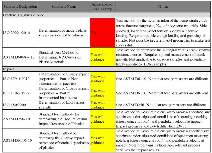
NISTIR 8059

   Materials Testing Standards for
Additive Manufacturing of Polymer
    Materials: State of the Art and
           Standards Applicability
                                            Aaron M. Forster

               This publication is available free of charge from:
                       http://dx.doi.org/10.6028/NIST.IR.8059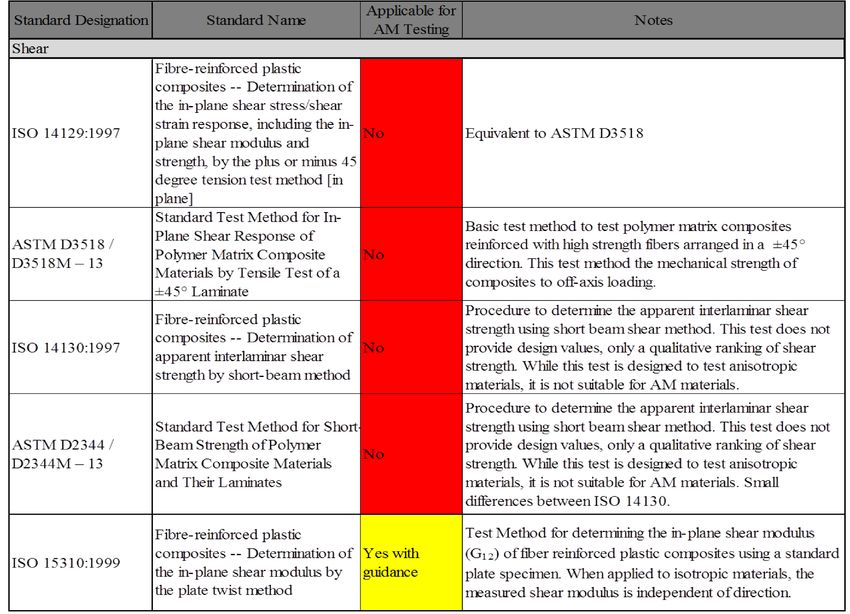
NISTIR 8059

   Materials Testing Standards for
Additive Manufacturing of Polymer
    Materials: State of the Art and
           Standards Applicability
                                                              Aaron M. Forster
                                      Materials and Structural Systems Division
                                                        Engineering Laboratory

                               This publication is available free of charge from:
                                       http://dx.doi.org/10.6028/NIST.IR.8059

                                                                          May 2015

                                                     U.S. Department of Commerce
                                                              Penny Pritzker, Secretary

                                        National Institute of Standards and Technology
     Willie May, Under Secretary of Commerce for Standards and Technology and Director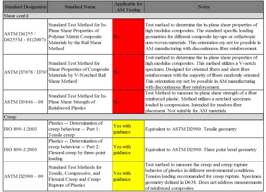
National Institute of Standards and Technology Interagency Report 8059
                               54 pages (May 2015)

                       This publication is available free of charge from:
                           http://dx.doi.org/10.6028/NIST.IR.8059

Certain commercial entities, equipment, or materials may be identified in this document in order to
describe an experimental procedure or concept adequately. Such identification is not intended to imply
recommendation or endorsement by NIST, nor is it intended to imply that the entities, materials, or
equipment are necessarily the best available for the purpose.
There may be references in this publication to other publications currently under development by NIST
in accordance with its assigned statutory responsibilities. The information in this publication, including
concepts and methodologies, may be used by Federal agencies even before the completion of such
companion publications. Thus, until each publication is completed, current requirements, guidelines,
and procedures, where they exist, remain operative. For planning and transition purposes, Federal
agencies may wish to closely follow the development of these new publications by NIST.
Organizations are encouraged to review all draft publications during public comment periods and
provide feedback to NIST. All NIST Computer Security Division publications, other than the ones
noted above, are available at http://csrc.nist.gov/publications.

                   Comments on this publication may be sent to:
                        National Institute of Standards and Technology
              Attn: Computer Security Division, Information Technology Laboratory
               100 Bureau Drive (Mail Stop 8930) Gaithersburg, MD 20899-8930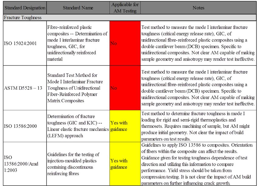
Abstract

Additive manufacturing (AM) continues to grow as an advanced manufacturing technique. The
most recent industry report from Wohlers and Associates indicates AM represented $1.6B in
revenue from parts, systems, and other supporting industries in 2012 and is expected to grow to
more than $3.5B by 2017 and to $10B by 2022. The measurement challenges for AM, whether
the deposited material is metal or polymer, are similar. Parallels between the additive
manufacturing for metals and polymers include: characterization of raw materials, development
of material properties for design, in-situ process and feedback control, workflow optimization,
and modeling final properties. The scope of this report is to analyze the current trends in polymer
additive manufacturing and determine the applicability of current American Society for Testing
Materials International (ASTM) and the International Standards Organization (ISO) standard test
methods for mechanical properties and failure of polymers and polymer composites generated
from the additive manufacturing processes. The current approach to mechanical testing standards
utilizes existing guidelines for testing materials, but this analysis highlights the need to develop
specific guidelines for testing AM materials. The current AM efforts at NIST towards polymers
are supported through the Material Measurement Laboratory (MML) AM program. While this
program is addressing critical measurement science to validate polymer physics within AM, it is
not directly translating this knowledge into the standards required for engineering design. The
emerging engineering and standards challenges for high performance polymers and polymer
composites are not currently addressed by the Engineering Laboratory (EL) Additive
Manufacturing program, which is focused on metal applications. The development of a program
to bridge the measurement gap between molecular architecture of AM materials (MML) and
generating engineering properties for design represents an opportunity for the EL effort.

Key words: additive manufacturing, polymer, mechanical properties, standards, testing

                                                                                                   i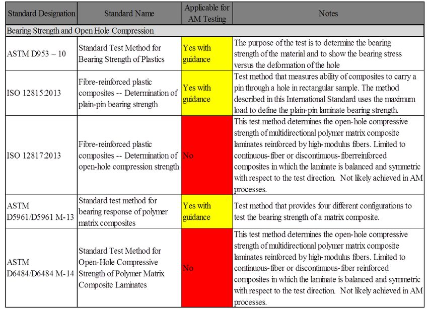
Table of Contents
Table of Figures ............................................................................................................................. iii
List of Acronyms ........................................................................................................................... iv
1. Introduction: ............................................................................................................................ 1
2. Scope: ...................................................................................................................................... 3
3. Government and Academic Support: ...................................................................................... 4
4. Materials: ................................................................................................................................. 6
5. Mechanical Properties for Design: .......................................................................................... 9
6. Challenges for Mechanical Property Characterization: ......................................................... 15
7. Overview of Standard Testing Methods ................................................................................ 19
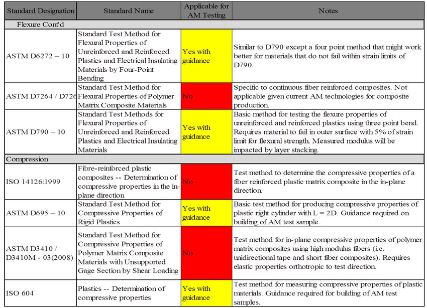
7.1. Tension ........................................................................................................................... 19
7.2. Flexure............................................................................................................................ 19
7.3. Compression ................................................................................................................... 20
7.4. Shear ............................................................................................................................... 20
7.5. Creep .............................................................................................................................. 20
7.6. Fatigue ............................................................................................................................ 21
7.7. Fracture Toughness ........................................................................................................ 21
7.8. Impact ............................................................................................................................. 22
7.9. Bearing Strength and Open Hole Compression ............................................................. 23
8. Standards Applicability Assessment ..................................................................................... 23
9. Polymer Additive Manufacturing at NIST ............................................................................ 32
10. Conclusion and Path Forward................................................................................................ 33
Acknowledgements ....................................................................................................................... 35
References ..................................................................................................................................... 36
ii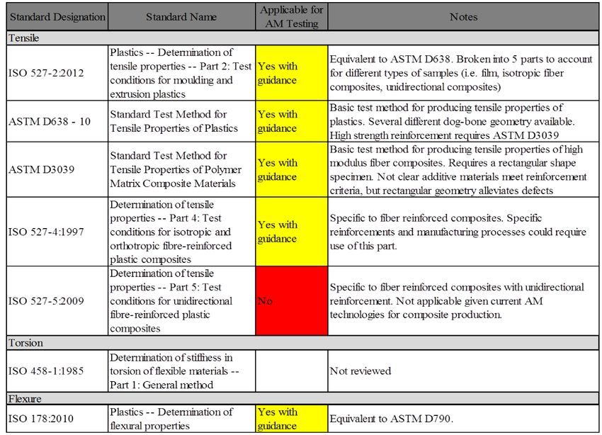
Table of Figures

Figure 1: Pie chart showing the types of material utilized for AM as fraction of material
consumed by AM from a user survey. [15] .................................................................................... 7

Figure 2: Building block integration for the development of composite structures [53].............. 10

Figure 3: Building block approach for the support of composites structures in the 777 aircraft
[53]. In this graphic durability is defined through moisture stability, temperature stability, creep
resistance, and fatigue resistance. ................................................................................................. 11

Figure 4: Mesostructure of an ME-ABS material illustrating the porous structure that may be
achieved based on the raster angle and bead overlap [54]. ........................................................... 12

Figure 5: Graphic illustrating the directionality of fibers, through z, in a fiber composite
laminate. The orientation and number of fibers controls the performance of the composite. ...... 13

Figure 6: Three modes of crack surface displacements Mode I (opening or tensile mode), Mode
II (sliding mode), and Mode III (tearing mode) copied from [56]................................................ 14

Figure 7: Graphical representation of process variables related to the build geometry for additive
manufacturing. a) raster angle, b) extruded filament height and layer width, c) air gap between
extruded filaments, d) combinations of variables (T, air gap, width, height, velocity) can increase
the coalescence between filaments, e) the build direction can affect the load transfer between
filaments and interfaces. ............................................................................................................... 16

                                                                                                                                         iii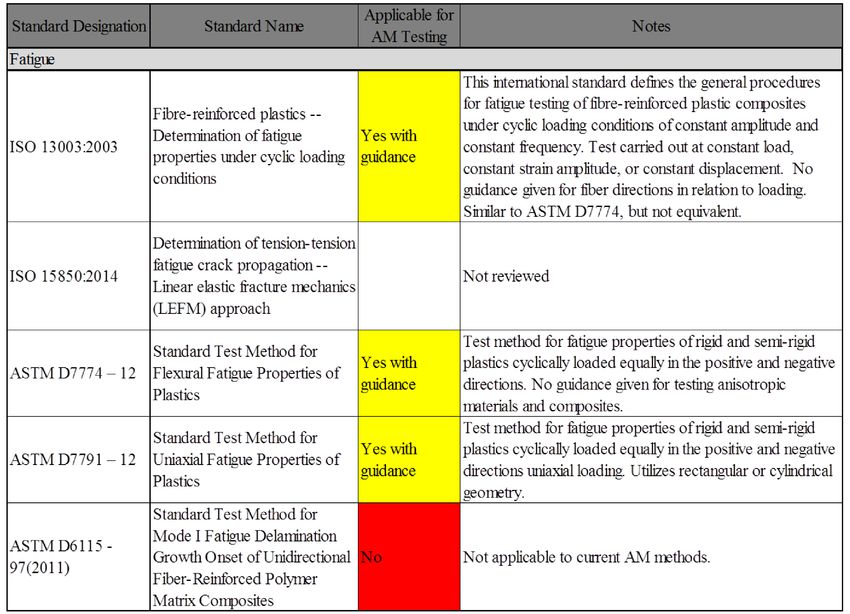
List of Acronyms
AMC, Additive Manufacturing Consortium – A national consortium of industry, government,
academic, and non-profit research organizations with the mission of accelerating and advancing
the manufacturing readiness of metal additive manufacturing technology.

AM, additive manufacturing – a process of joining materials to make objects from 3D model
data, usually layer upon layer, as opposed to subtractive manufacturing methodologies [1].

AmericaMakes – is the National Additive Manufacturing Innovation Institute. AmericaMakes is
focused on helping the United States grow capabilities and strength in 3D printing. It is based in
Youngstown, Ohio and is an extensive network of more than 100 companies, non-profit
organizations, academic institutions and government agencies [2].

ARL - Army Research Laboratory.

ASTM – American Society of Testing Materials International.

Battelle – Battelle Memorial Institute is the world’s largest nonprofit research and development
organization.

CAD/CAM – Computer Aided Design/Computer Aided Machining.

CAMM, Consortium for Additive Manufacturing Materials – The organizational component
of CIMP 3D. It was created from a NIST Advanced Manufacturing Technology Consortia
(AMTech) Program grant to foster innovation in additive manufacturing.

CIMP 3D, Center for Innovative Materials Processing Through Direct Digital Deposition –
A consortium administered by Pennsylvania State University, Batelle, and Sciaky Corporation. It
is a resource for AM technology for critical applications [3].

CNC, computer numerical control – indicative of computer-controlled machinery for cutting
various hard materials. These are synonymous with subtractive manufacturing methods.

DARPA – Defense Advanced Research Projects Agency.

FDM – a material extrusion process used to make thermoplastic parts through heated extrusion
and deposition of materials layer by layer; term denotes machines built by Stratasys, Inc [1].

ISO – International Standards Organization.

LS, laser sintering – a powder bed fusion process used to produce objects from powdered
materials using one or more layers to selectively fuse or melt the particles at the surface, layer by
layer, in an enclosed chamber [1].

                                                                                                   iv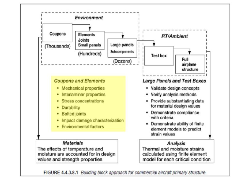
NAMII, National Additive Manufacturing Innovation Institute - The pilot institute from
NNMI established in 2012. This consortium includes 40 companies, nine research universities,
five community colleges, and 11 nonprofit organizations. This consortium is also called
AmericaMakes [4].

NCDMM, National Center for Defense Manufacturing and Machining – the driver of
AmericaMakes. The mission is to deliver optimized manufacturing solutions that enhance the
quality, affordability, maintainability, and rapid deployment of existing and yet-to-be developed
defense systems [5].

NNMI, National Network for Manufacturing Innovation – A federally backed network
established by the Revitalize American Manufacturing Act. The institutes developed under
NNMI are intended to create a competitive, effective, and sustainable manufacturing research-to-
manufacturing infrastructure for U.S. industry and academia to solve industry-relevant problems.
ME, material extrusion – an additive manufacturing process in which a material is selectively
dispensed through a nozzle or orifice [1].

MSAM, Measurement Science for Advanced Manufacturing – A cooperative agreement
program that solicits proposals for grants to advanced manufacturing. The program is
administered by the National Institutes of Standards and Technology. This is the program
developed to administer grants for the NNMI.

ONR – Office of Naval Research

ORNL – Oak Ridge National Laboratory

                                                                                                    v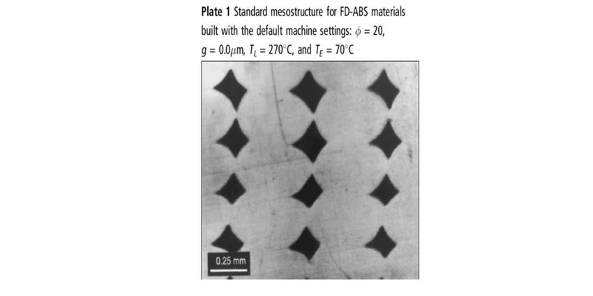
1. Introduction1:
Additive manufacturing is a process of joining materials to make objects from 3D model data,
usually in a layer by layer process [1, 6]. The objects are created in CAD/CAM software,
transformed to machining instructions similar to the process for CNC machining, and each layer
is directly fabricated on top of previous layers to create a replica of the object. In general, this
manufacturing process is not subtractive. Multiple processes exist to create polymeric materials
and composites, but they generally fall into three classes: material extrusion, powder bed fusion,
and material jetting.

Material Extrusion (ME) is a process that selectively dispenses a thermoplastic polymer through
a nozzle. Stratasys has trademarked the term fused deposition modeling (FDM®) to identify their
systems that utilize this technique [1]. The extrusion head melts the plastic filament, extrudes
material through a nozzle, and places the resin bead onto the substrate. This is a less aggressive
process compared to injection molding where the plastic is melted and uniformly blended using a
screw extruder to inject the material at high pressure into a mold. There are specific challenges
for additive manufacturing that are unique to polymeric materials. In ME, heat is used to melt a
polymer filament and the material is directed to a specific location via a nozzle. This places a
polymer beads or filament of a specific size and length onto the substrate. Successive beads are
layered to create the final 3D structure. The strength of the part is generated from the deposited
material properties and the interface between beads. The interface is important because the
neighboring beads are at a lower temperature than the molten bead leaving the nozzle. The
thermal gradient between the two materials will melt the existing bead and cause polymers
molecule to diffuse across the interface. The strength of this fusion is dependent on many factors
such as temperature gradient, polymer structure (molecular weight, branching, heat of fusion,
glass transition temperature, etc.), and bead geometry. It is possible for this fusion to exist under
stress prior to any mechanical loading. As the beads cool, the polymer contracts which creates a
localized residual stress. As the performance of AM materials is increased by using semi-
crystalline and more rigid polymers, the physics to model interfacial strength and stress are
different than amorphous materials. There are additional challenges such as ME surface
roughness, void space between beads, and defects (excess material) that can initiate failure
modes within the part under loading. The nature of the printing process and the aligned structure
of the beads make AM parts highly anisotropic and this anisotropy may exhibit a non-linear
dependence on processing parameters.

Laser sintering (LS), or powder bed fusion, is a process that utilizes directed energy to melt a
thermoplastic powder similar to the process used to generate parts from metal powders. This
process starts with a powder bed of polymer powder of a specific layer height and temperature.
A high powered laser is rastered across the surface to locally heat the polymer pellets. At this

   1
     Certain commercial equipment, instruments, or materials are identified in this paper to
   foster understanding. Such identification does not imply recommendation or endorsement by
   the National Institute of Standards and Technology, nor does it imply that the materials or
   equipment identified are necessarily the best available for the purpose.

                                                                                                   1
point, two thermal processes could occur depending on the machine design. The laser could fully
melt the polymer pellets and allow the molten material to flow and diffuse into adjacent material.
The second process locally heats the pellets to allow diffusion of polymer between adjacent
pellets and layers. This is equivalent to a sintering process. In either case, the locally heated
polymer diffuses to create a single layer within the part. A fresh layer of powder material is
placed on top of the previous layer and the laser again melts local regions of polymer. The
strength of parts is dependent on the ability of the process to manage thermal gradients. The
molten material must flow into cracks adjacent to previous layers and the thermal gradient must
be high enough to allow entanglement between neighboring polymer layers [7]. These parts tend
to exhibit anisotropy characteristic of the laser scanning direction or build (Z) direction and can
exhibit location dependent voids.
The material jetting process, which is similar to early stereolithography methods used for rapid
prototyping [8], utilizes an inkjet print head to deposit a thin layer of photopolymerizable
polymer and initiator. Ultraviolet lamps, or similar energy source, at the print head initiate cure
of the photopolymer layer as it is deposited [9]. Direct printing processes have challenges related
to the chemistry of the photocurable polymers used to build parts. Localized curing may be
inhomogeneous which leads to a range of mechanical properties throughout the part.
Uncrosslinked material trapped within holes may plasticize or age the part causing premature
failure [10].
Additive manufacturing (AM) continues to grow as an advanced manufacturing technique. The
most recent industry report from Wohlers and Associates indicates AM represented $1.6B in
revenue from parts, systems, and other supporting industries in 2012 [11] and is expected to
grow to more than $3.5B by 2017 [12] and to $10B by 2022 [13]. The AM material market is
expected to grow from $470M in 2013 to over $1.09B in 2022 [13]. Industry, government and
academia in the U.S. have been working to support the rate of growth by expanding machine
capabilities and developing new high strength and biomedical materials. A report by IDTechEx
as reported in The Guardian indicates the dental and medical market is expected to expand to
$867M by 2025, the inclusion of additively manufactured organs and tissues would mean a
potential of $6B within 10 years [14, 15].
Currently, there are few standards specifically addressing mechanical properties of AM parts.
ASTM F42.01 has a number of standards and work items focused on metals AM [16]. There is
currently one ASTM standard test method applicable to powder bed fusion of plastic materials;
F3091/F3019M-14 Standard Specification for Powder Bed Fusion of Plastic Materials [17]. The
subcommittee has one work item that covers evaluation of manufacturing systems: WK 40419
New Test Methods for Performance evaluation of additive manufacturing systems through
measurement of a manufactured test piece [18]. The International Standards Organization (ISO)
has one active standard: ISO 17296-3:2014 Additive Manufacturing – General Principles—Part
3: Main characteristics and corresponding test methods [19] to address quality characteristics of
parts produced by AM. This standard references other ISO standards for mechanical property
testing of polymers and metals, but there are no AM specific considerations in testing. The lack
of AM specific mechanical standards creates challenges for stakeholders to provide equal
comparisons between machines, materials, and models that predict final part properties in order
2to generate design allowables. Stahl has identified the inferior mechanical performance
compared to that for traditionally manufactured parts as a risk for AM [20].
2. Scope:
The measurement challenges for AM, whether it is metal or polymer, are similar. Parallels
between the material systems include: characterization of raw materials, development of design
allowables, in-situ process and feedback control, workflow optimization, and modeling final
properties [21]. The emerging engineering and standards challenges for high performance
polymers and polymer composites are not directly addressed by the Engineering Laboratory
Additive Manufacturing program, which is focused on metal applications. The scope of this
report is to analyze the current trends in polymer additive manufacturing and determine the
applicability of current ASTM and the ISO standard test methods for mechanical properties and
failure of polymers and polymer composites generated from the additive manufacturing
processes.
This report follows the style of previous NIST Internal Reports (NISTIR), NISTIR 8005 [22] and
NISTIR 7847 [23], from EL to document the standards needs in metal AM. This report will
provide:
a. State of the art for additive manufacturing of polymers and polymer composites
b. Analysis of the technical hurdles that are preventing these materials from high
performance manufacturing applications.
c. Analysis of the current ASTM and ISO standards for measuring mechanical
properties and failure of polymers and composites to include:
i. Standard designation,
ii. Standard Name,
iii. Application to AM testing,
iv. Notes concerning each standard relevant to the AM,
d. Summary of recommended potential directions for NIST standards research in
polymer additive manufacturing.
This report will also describe the emerging effort in the Material Measurement Laboratory
(MML) to support polymer additive manufacturing efforts and the potential opportunities for
leveraging collaborative efforts between MML and the Engineering Laboratory. In order to limit
the scope of this effort, concessions were made to focus on materials, measurement length scales,
and types of standards as described below:
• Polymers– Standardized methods for measuring the mechanical properties polymeric materials
utilized in ME, laser sintering, and direct printing were addressed. Mechanical property
measurement standards for polymer matrix fiber reinforced composites were also included for
review. Fiber reinforced composites use a polymer matrix to support woven or aligned high
strength fibers. Manufacturing composites requires stacking multiple layers of fibers and
infusing the interstitial spacing with a polymer resin. The fibers are strong in the axial direction
3and weaker in the radial direction; the fibers provide anisotropy to the strength of the composite.
Therefore, standardized measurements developed for mechanical properties in fiber reinforced
composites may be applicable to additively manufactured materials.
• Bulk Mechanical Properties – Standardized methods for bulk property measurements were
addressed. Mechanical property measurements of localized properties, like those obtained by
micro-indentation, hardness, and atomic force microscopy were excluded.
• Focus on International Standards – This was done in order to make the assessment practical. A
cursory review of standards from the major Standards Development Organizations showed that
ASTM and ISO mechanical testing standards are representative of all the pertinent standardized
mechanical testing methods. A number of industry groups have developed protocols for
reference tests. These tests are useful and some eventually become standards. Such tests are
not covered here for three reasons: there are many such tests, often they are specific to an
industry sector or product, and many are consensus methods that may lack the rigorous
scientific basis and round-robin verification that is required for a standard.
3. Government and Academic Support:
In 2009 the National Science Foundation (NSF) developed a Roadmap for Additive
Manufacturing [24]. This roadmap addressed various challenges faced by the industry in the
areas of design, materials, biomaterials, and energy and sustainability. The main
recommendations from this roadmap were to:
expand the capabilities of solid modeling to support additive manufacturing,
develop better closed loop and feedback control,
develop predictive process-structure-property relationships integrated into CAD/CAM
tools,
improve physical models of AM processes to maximize the properties of AM parts,
develop and adopt internationally recognized standards which are useful to product,
process, and material certification
Chapter 6 of this report highlights the types of material properties that are measured to
determine the engineering properties used to design structures. In addition, understanding the
anisotropy of AM parts allows specific functionality to be built into the manufacturing process
and this allows unique capabilities not achievable through other manufacturing methods. NSF
funded additive manufacturing to a total of $200M from 1986 to 2012 [24].
In 2012 the creation of the National Network for Manufacturing Innovation (NNMI) was started
by the Executive Office of the President to develop regional advanced manufacturing hubs [4].
One of the first hubs was AmericaMakes. AmericaMakes is a partnership among the
Departments of Commerce, Defense, Energy, NASA, and NSF. This effort led to the funding of
the National Center for Defense Manufacturing and Machining (NCDMM) in Youngstown Ohio,
which brings together a regional network of 14 research universities, community colleges, 40
industry partners, and 10 non-profit organizations spanning Western Pennsylvania, Eastern Ohio,
and West Virginia. This effort is funded with a $40M private match to the initial $30M federal
4investment. NIST’s Measurement Science for Advanced Manufacturing program (MSAM) has
funded NCDMM with $5M for research to ensure quality parts are produced from LS of metal
powders [25]. The NCDMM mission is to build a national network for additive manufacturing
and 3D printing technologies in the U.S. [5].
Currently, AmericaMakes is funding projects for ME processing of high-temperature
commercial polymers, ME for complex shape composite tooling, and AM manufactured
composite tooling for hydroforming. The University of Texas at El Paso has formed the
W.M. Keck Center for 3D Evaluation which has one project to develop integrated technologies
for multi-material structures [4]. In addition, materials characterization, quality control, data sets
for process-property validation, and tailored materials have been identified as critical topic areas
in both project calls from AmericaMakes.
Additive manufacturing has led to several centers of development within academia. The first
freeform manufacturing center was started in 1988 at The University of Texas at Austin.
Pennsylvania State University started the Center for Innovative Materials Processing through
Direct Digital Deposition (CIMP-3D) for metallic AM with the following government partners:
DARPA, ONR, and Battelle. This consortium is developing an advanced process modeling and
analysis framework for metal manufacturing. This framework includes incorporation of material
science principles (microstructure, kinetics, and thermodynamics) to predict and control the final
properties of the additive manufactured part. The Consortium for Additive Manufacturing
Materials (CAMM) was started in 2013 as part of the NIST AMTech program ($500K) and will
develop a comprehensive roadmapping effort for new types of additive materials [26]. The
American Lightweight Materials Innovation Institute is a partnership between the Edison
Welding Institute, The Ohio State University, and the University of Michigan. The University of
Connecticut has recently opened the Pratt & Whitney Additive Manufacturing Innovation Center
to focus on metals. The Michigan Technological University hosts the Open Sustainability
Technology Laboratory. This laboratory supports the development of open source software and
hardware for all forms of additive manufacturing. The goal is to make additive manufacturing
technology fully accessible to any user. North Carolina State University hosts the Center for
Additive Manufacturing and Logistics. Northern Illinois University was awarded $2.4M through
the NIST MSAM program to develop physics-based AM models for process control and quality
assurance [25]. Many of the academic efforts focus on the development of new materials,
improvement of existing materials, development of instrumentation and test methods, and
process material-property relationships for aerospace and biomedical applications. There is
overlap within projects, but they are directed at improving the AM process and final products.
Additive manufacturing has recently been demonstrated for more than small parts and devices.
Oak Ridge National Laboratory has partnered with Cincinnati Incorporated to develop a large-
scale polymer additive manufacturing system, with a goal of increasing speed by 500 times and
building components that are 10 times larger (> 1 m3) than typical AM parts [27, 28]. Local
Motors is a company that specializes in the development of large area additive manufacturing
machines. This company additively manufactured an automobile during the International
Manufacturing Technology Show within the exhibition hall [29]. They have recently opened an
office in the National Harbor area of Washington D.C.; the large scale printer and polymers used
for this demonstration were developed through collaborative research supported with ORNL.
5Andrey Rudenko additively manufactured a 2-story concrete home in the shape of a castle out of
concrete [30]. While these applications remain a technical curiosity, they represent the desire to
push the industry to stronger materials and applications critical to life safety.
One of the advantages of additive manufacturing is the accessibility of the technology to
individuals, especially for soft materials. A large community of do-it-yourself consumers has
grown up to provide open source plans for building machines, control software, start new small
manufacturing businesses, and release of downloadable CAD drawings. The ease of technology
transfer has spurned innovations in manufacturing at all levels. The growth of sub-$5K
consumer-level printers is expected to increase [31]. Further information on advances in the open
source additive manufacturing market may be found at RepRap project [32] and Makerspace
[33] websites.
The significant investment in AM from public-private partnerships, entrepreneurs, and the
general public is expected to lead to new manufacturing technologies, better materials, and new
markets for AM. Engineers require science-based standards to support design and validate
mechanical performance. Machine manufacturers require methods to predict performance based
on processing parameters (e.g. extrusion temperature, extrusion nozzle shape, extrusion velocity,
etc.), which requires incorporation of polymer physics, constitutive equations, and improved
process control methodologies. Standards will be critical to supporting competitiveness as these
efforts mature to widely available manufactured products.
4. Materials:
Polymers are critical for AM because they represent the greatest market penetration and user
accessibility [31][32][33]. The importance of polymers to materials in this community has been
documented through a survey of “commons based peer production” of users available through
the web [34], where polymers represent the major source of printable materials. This was a
survey conducted within the open source community, mentioned earlier, to gauge their materials
and manufacturing needs. Figure 1 shows the breakdown of materials used in AM printing by
tonnage used in 2013. Photopolymers generated over $239M in market revenue and the market is
expected to reach $470M in 2022 [13]. Laser sintering equipment is not yet easily obtained by
most non-manufacturing consumers because of the cost of the equipment and the difficulties in
handling dispersible metal powders. Although polymers lag metals in the development of
structural mechanical properties, the potential to impact many more markets from consumer
products, sustainable applications, advanced manufacturing, and biomedical devices is far
greater for polymers [15].
6Figure 1: Pie chart showing the types of material utilized for AM as fraction of material
consumed by AM from a user survey. [15]
There are a number of polymeric materials available from machine manufacturers and choices
are dependent on the methodology used to create objects. A survey of websites from major
equipment manufacturers, Statasys [35], 3D Systems [36], and Makerbot [37], reveal material
choices that include acrylonitrile-styrene-butadiene (ABS), polycarbonate (PC), polylactide
(PLA), toughened polystyrene, nylon, toughened polycarbonate, and polyurethane. Many of
these materials are toughened to improve impact and fracture performance, but it is not clear
whether AM takes full advantage of these properties. These materials are mainly employed for
prototyping designs and the creation of low performance parts, but the demand for new higher
performance polymer materials and composites is growing.
There are several examples of advances in materials, machines, and control strategies to support
these advances. Equipment manufacturers offer materials that perform at high temperatures, and
are chemically resistant such as polyphenylene sulfide (PPS), polyetherimide (PEI),
polyphenylsulfone (PPSU), and polyether ether ketone (PEEK). There are composites systems
based on glass fibers, carbon fibers, and dispersed nanomaterials [38]. The car produced via
material extrusion at the International Manufacturing Technology show utilized a discontinuous
carbon fiber composite developed at ORNL through the DOE Manufacturing Demonstration
Facility [39]. There are additional technologies to print both discontinuous and continuous
carbon fiber composites [39, 40]. Arevo Labs has announced, through a press release, the
capability to print multiple high performance polymers using a combination of Solvay polymers
paired to advanced instrumentation control, with a claim to deliver parts designed to achieve
predicted performance [41, 42]. The Army Research Laboratory (ARL) has demonstrated the
capability to produce multi-functional composites using an electric Field-Aided Laminar
Composite (FALCom) processing technique [43]. This process utilizes electric fields to align
nano- and micro- particles into chain-like structures that are cured into place in the
photopolymer. This increases strength and provides conductive pathways for multifunctional
performance. Finally, a survey of recent meeting abstracts and industry press releases show the
7industry is moving towards printing multiple materials, colors, and functionality within the same
part. This will increase the complexity in predicting the final properties of the object or system.
While the choices for materials and manufacturing processes continue to improve, the ability of
stakeholders to compare materials/machines for development of part design and performance has
not followed a parallel path. Performance property information within the technical data sheets
for these materials is not standardized. There are no defined standards to classify materials or
standardized processing/manufacturing parameters used to specify the properties of a final part.
A search of the technical data sheets for materials used in additive manufacturing that includes
fused deposition and direct printing materials provides an idea of the important mechanical
properties and the standard tests used to specify those properties. The standards are ASTM D638
(tensile strength, elongation at break, modulus of elasticity) [44], ASTM D790 (flexural strength,
flexural modulus) [45], ASTM D256 (Izod Notched Impact) [46], and various hardness scales.
According to ASTM D5592 [47], several of the above-referenced ASTM standards are
applicable to the development of engineering design properties for load-bearing plastic
components. These include ASTM D638 (tensile), ASTM D695 (compression) [48], ASTM
D2990 (creep) [49], ASTM D3418 (transition temperatures for semi-crystalline polymers) [50],
ASTM D4473 (dynamic mechanical for cure behavior) [51], D5045 (plane-strain fracture
toughness) [52], ASTM D5279 (dynamic mechanical properties in torsion). ASTM D5592 [47]
was used to identify the ASTM standards typically used in engineering design of plastics for this
survey.
While manufacturers provide some traceability to mechanical property testing, the information is
not complete. For example, some manufacturers provide printing parameters and others provide
no printing parameters. The quality assurance provided on the raw materials prior to printing is
not defined and polymers remain a black box. Manufacturers control their interactions with
suppliers and the resins are tailored for their machines. Variability within molecular weight and
distribution, dispersed phase volume concentration, viscosity, void content, crystallinity, range of
additives and other performance qualities required for a specification are not reported. These
materials are still fabricated for existing, conventional manufacturing processes such as
compression or injection molding. The range of melt parameters, e.g. melt viscosity or melt
index, for a commercial extrusion/injection process may not be compatible for the AM process
and the lack of standardization has led to material disclaimers provided on technical datasheets,
for example:
"The performance characteristics of these materials may vary according to
application, operating conditions, or end use. Each user is responsible for
determining that the Stratasys material is safe, lawful, and technically suitable
for the intended application, as well as for identifying the proper disposal (or
recycling) method consistent with applicable environmental laws and
regulations. Stratasys makes no warranties of any kind, express or implied,
including, but not limited to, the warranties of merchantability, fitness for a
particular use, or warranty against patent infringement. The information
presented in this document are typical values intended for reference and
comparison purposes only. They should not be used for design specifications or
quality control purposes. End-use material performance can be impacted (+/-)
8by, but not limited to, part design, end-use conditions, test conditions, color, etc.
Actual values will vary with build conditions. Tested parts were built on Fortus
400 mc @ 0.010” (0.254 mm) slice. Product specifications are subject to change
without notice.”[35]
As will be demonstrated in the specific standards discussion below, process variables and
manufacturing design can lead to final parts with anisotropic, inconsistent or substandard
performance.
5. Mechanical Properties for Design:
Accurate mechanical property measurements are required to select materials and design a
structure for its intended application. Engineers utilize this knowledge to make material
decisions in both safety-critical and non-safety critical designs. These properties are determined
using accepted measurement standards, certified databases, or reference materials. Applicable
test standards are determined based on the final usage of the material, inherent weakness in the
design, durability requirements, and safety factors. The Department of Defense Composite
Materials Handbook has a useful reference that illustrates the staged process of a “building block
approach” for determining the properties of the material and transitioning that information to the
performance of the system [53]. Figure 2 shows the building block approach utilized to minimize
the risk of new material insertion into aerospace structural systems. The building blocks to safely
incorporate new materials into structural design rely on increasing the scale of testing from
coupon tests to more complex component tests and finally full scale tests. This approach will be
used to illustrate where standards for mechanical property measurements of AM manufactured
parts are needed to incorporate new materials or designs into systems.
The parameters that define the system are collected within the design considerations (lower
block, purple in figure). Engineers require estimates of the loading, temperature, moisture
environment of the application, and material information such as mechanical properties, long
term stability, susceptibility to damage, and manufacturing cost prior to designing a part. Design
considerations for AM follow the same requirements as any other manufacturing process.
Supporting technologies (left block, yellow in figure) are the technologies to obtain, measure, and
validate the material information. In AM, this can be difficult because material property
information is often controlled by manufacturers and dependent on AM processing. The engineer
must decide how material properties will be validated through standard test methods, how
statistical analysis will be done to determine the properties of the population, estimate the needs
for post-processing of the part, and determine whether non-destructive techniques are required to
validate internal structural dimensions. If these properties are dependent on material source and
machine manufacturer such as in AM, it becomes difficult to estimate the level of Supporting
Technologies required. The Building Blocks bring all of these considerations together (center
block, green in figure). The building blocks allow engineers to understand material performance,
joining or bonding performance, performance of components working together, and finally full
incorporation into a full scale system test. In AM this may require significant effort for coupon
level tests such as printing a single bead of material to optimize extrusion parameters, moving to
ASTM dog bone geometries to identify optimal print layouts and finally incorporating the AM
part into the other elements and components for further testing. In today’s modeling intensive
9world, many of these concepts are validated via simulation. Therefore, science-based
standardized testing is required for AM materials to support accurate simulations. This testing
requires confidence in material mechanical properties and performance, which is an area that
AM is lacking.
Figure 2: Building block integration for the development of composite structures [53].
The building block integration approach (Figure 2) may be further expanded to highlight the type
of information gathered from each of the building blocks. Figure 3 shows the building block
approach for a commercial aircraft composite primary structure to provide an estimate of the
level of experimental effort anticipated at each stage of the building block. The use of aggressive
environments (Environment) allows engineers to scale allowed loading or strain limits for the
material based on the effects of temperature, moisture, or cycling. Coupon level testing relies on
simplified sample and test geometries that deliver specific information such as mechanical
properties (modulus, strength, etc.), interlaminar properties, adhesive properties, and durability
(highlighted Coupons and Elements). These tests may easily number in the thousands to build
statistical confidence in performance. Success beyond the coupon level leads to manufacturing
smaller structures with increasing complexity for assembly (inclusion of joints and bolts) and
loading (stress concentrations, off-axis loading). The costs per subcomponent increase, therefore,
sampling is smaller. The coupon level and element level require a firm understanding of the
impact of manufacturing processes on performance, and demand a science-based standardized
testing framework to increase success in the final subcomponent stage. For any processes,
weaknesses must be identified at this time to prevent costly engineering choices in the final
structure and before manufacture and testing of large panels or subcomponents. An additive
part will readily cross between the coupon and element level because performance may be
defined by internal fusion joints, print directions, manufacturer, additive method, and material
supplier. Large panels permit the validation of the design concepts and analysis methods are
10fully validated. Failure or success of the structure can validate the material design values
developed from earlier testing. Each level of testing is used to support structure performance
models to reduce test costs, but models rely on accurate material and interface property
measurements. Accurate material and interface property measurements rely on a solid
framework.
Figure 3: Building block approach for the support of composites structures in the 777 aircraft
[53]. In this graphic durability is defined through moisture stability, temperature stability, creep
resistance, and fatigue resistance.
From the stratified view of the building block manufacturing or qualification approach, there are
identifiable challenges for AM. The first challenge is the identification of test methods for
characterizing the mesostructure of the AM part at both the structural level and the molecular
level. The mesostructure is defined at the structural level by anisotropy in the axial direction of
extruded material, the presence of voids, and the degree of curing between reacted or melted
layers during the deposition process. Many AM systems allow for complete infill (no voids) for
ME and voids may not be as prolific in sintering, this does not eliminate anisotropy in
mechanical performance. The mesostructure at the molecular level is defined by the degree of
mixing between polymers with differing thermal histories, degrees of dispersion in composites,
the coefficient of thermal expansion mismatches, and the adhesion between dissimilar materials.
Both length scales lead to anisotropy in performance. Figure 4 is a cross-section of an ME
produced part that highlights the potential mesostructure present from incomplete bonding
between lines of extruded material. The majority of literature concerning material extrusion
processes addresses the impact of different void space between lines of extruded material,
11orientation of beads to load direction, and the influence of build direction. The current focus for
this overview will be the combination of material direction and void space that leads to the
structural level mesostructure. These types of porous structures represent a significant challenge
for engineers to determine safe design parameters. Engineers need to understand the strength of
the fusion, strength of the bead, and the micromechanics of a porous structure. Standards
provide the framework of scientifically grounded test geometries and methodologies to address
the challenges of AM and facilitate a smooth transition between boxes to produce design
parameters.
Figure 4: Mesostructure of an ME-ABS material illustrating the porous structure that may be
achieved based on the raster angle and bead overlap [54].
Given the complicated mesostructure of AM parts, the scope of this standard review was
expanded to include standard tests used for fiber composite materials. Fiber composites are
lightweight structural materials that contain high strength fibers (E~70 GPa to 250 GPa)
embedded in a polymer matrix material (E~ 3 GPa to 4 GPa). The fibers carry any significant
loads and the matrix is designed to provide rigidity to the fiber structure. Since the fibers are
stronger in the axial direction, the resulting composites can have significantly anisotropic
properties. This anisotropy has been addressed in standards by specifying the directionality of the
fibers. Figure 5 shows an example of fibers oriented in different x,y directions along the z-plane.
If this rotation is done symmetrically, the composite laminate may be considered quasi-isotropic
in material properties in the plane of the fibers. While geometry guidelines are critical for fiber
composites, it is not clear whether these are valid for AM materials since stress distribution
through the AM mesostructure will differ greatly from a fiber composite.
12Figure 5: Graphic illustrating the directionality of fibers, through z, in a fiber composite
laminate. The orientation and number of fibers controls the performance of the composite.
Mechanical properties: These properties are often defined in terms of the behavior at loads that
do not produce failure or failure behavior itself. For solids, the first case is generally
characterized by moduli that are defined as the stress divided by the strain. Moduli can be
measured with a number of different loading modes: tension, compression, flexure, shear, or
torsion [55], and in the linear region, they are proportionality constants independent of strain.
The moduli of polymeric materials are functions of temperature and time. These dependencies,
particularly temperature, are important. For many polymers used in additive manufacturing,
these properties are often reported in the technical specification sheet in tension (or compression)
and shear loading modes. Since two parameters are needed to model behavior in different
loading directions, an alternative is to report Young’s Modulus and Poisson’s Ratio. Poisson’s
Ratio is the negative ratio of transverse to axial strain.
Failure Properties: As the stress increases, materials begin to fail via plastic deformation (non-
linear stress vs. strain) or brittle fracture. One approach to quantify failure behavior is by
determining yield strength, ultimate strength, and impact strength. Each one of these may be
defined in relationship to the mode of loading: tension, compression, flexure, shear, or torsion
[55]. For many polymers used in additive manufacturing, these properties are often reported in
the technical specification sheet in tension or compression loading modes. On the other hand,
these parameters do not adequately characterize materials that fail by the propagation of cracks.
To describe this behavior requires fracture parameters that are often not reported in the technical
sheet [53]. The fracture toughness or fracture energy of the material is [55] defined in three
modes (I: crack opening, II: in-plane shear, and III: out of plane shear) as shown in Figure 6.
Standards are available to test in Mode I, Mode II, and mixtures of Mode I and II, although the
complex shapes of many AM parts may increase the importance of Mode III. Fracture toughness
is a critical factor for ME and LS created polymer parts and given the complex mesostructure
and anisotropy, it may be difficult to induce purely one loading Mode for testing.
13Figure 6: Three modes of crack surface displacements Mode I (opening or tensile mode), Mode
II (sliding mode), and Mode III (tearing mode) copied from [56].
The terms used to define failure properties are given below:
Yield Stress/Yield Strength
Ultimate Strength
Elongation at Yield
Elongation at Break
Fracture Toughness
Fracture Energy
Impact Strength
Bearing Strength
Open Hole Compression Strength
Crack Growth Resistance Curves
Bearing and open hole tests evaluate the ability of the material to perform with an engineered
flaw such as a bolt or pin in the structure.
Interlaminar properties are important for fiber reinforced composites. As shown in Figure 5, the
fibers lie in a plane and provide high strength and stiffness in that direction. Although designers
plan structures so the loads are in the fiber direction, unexpected events can produce loads
perpendicular to this plane, which causes damage. This can significantly reduce the performance
in the fiber direction, particularly compressive strength. Often the fiber-matrix interface
represents the weak point of the composite because it relies on bonding between the fiber filler
and the compliant matrix. Interlaminar test methods allow the user to understand the
susceptibility of the material to damage between fiber layers. Unfortunately, interlaminar
properties do not provide explicit engineering limits on the maximum load that a composite
material can bear in off-axis loading, but tests like interlaminar fracture and short beam strength
14can indicate general ranking. For composites, standard test methods for interlaminar properties
are:
Short beam strength
Shear modulus
Ultimate shear stress strength
Durability: Durable material properties may be quantified using several standards depending on
the usage of the material. In the context of this review, durability is addressed for mechanical
durability, specifically creep and fatigue. There are standards available in ASTM and ISO that
define exposure conditions for moisture, temperature, and artificial sunlight exposure on
materials. Creep is important for understanding the ability of the material to withstand long-term
static loading. Fatigue properties are important for understanding the ability of the material to
withstand cycling loading during usage. Finally, impact strength is a measure of the material to
withstand high strain rate loading and evaluate the ability of the material to absorb energy and
resist damage. Mechanical properties that define mechanical durability are:
Creep Modulus
Creep Rupture
Fatigue life (S-N plots/R-N plots)
Standards are important for mechanical and failure properties because they are the language that
mitigates risk within the design and allows engineers to build structural and safety critical parts
with a known performance window. The specific ASTM and ISO standards that are applicable to
quantify the material properties listed above will be addressed individually.
6. Challenges for Mechanical Property Characterization:
While AM provides the opportunity to quickly go from design to product especially for parts that
have difficult or impossible to machine features, challenges remain for predicting mechanical
performance. Many AM processes differ from traditional polymer processing in that not all of
the material is melted and homogenized. The AM process of depositing layers of polymeric
material results in parts with anisotropic properties, residual stress, and this is a significant
challenge. Researchers and Original Equipment Manufacturers (OEMs) must establish the
standardized methods to determine material properties from AM processing rather than the
mechanical properties of a particular design. Peer-reviewed literature has begun to highlight
complexity in relating material properties, AM mesostructure, and part design for standardized
testing. Despite the importance of this problem for the success of AM as a critical manufacturing
process, the literature available in this area is not significantly large. Figure 7 shows the typical
geometrical variables related to ME deposition geometry.
15Figure 7: Graphical representation of process variables related to the build geometry for additive
manufacturing. a) raster angle, b) extruded filament height and layer width, c) air gap between
extruded filaments, d) combinations of variables (T, air gap, width, height, velocity) can increase
the coalescence between filaments, e) the build direction can affect the load transfer between
filaments and interfaces.
The majority of studies have focused on the impact of raster angle, air gap, filament width, layer
height, and build orientation to major part axis (i.e. x, y, or z-direction). Build orientation allows
one to capture interacting factors such as filament length, temperature gradients, and nozzle
velocity on mechanical properties. Many additive systems that rely on material extrusion
processes allow for full infill of the deposited part, but it was not possible to compare literature
studies directly. Evidence for mechanical anisotropy was more readily identified in the literature
for powder bed fusion processes.
The impact of processing for anisotropic mechanical properties in material extrusion
has been identified by multiple authors with ME processing of ABS polymers as a major focus
[54, 57-68]. In the case of ME, AM parts exhibit inferior mechanical properties compared to the
as-received polymer filament that feeds the AM extruder head and compression molding or
injection molded parts constructed from this same as-received filament. Raster angle is a process
parameter that influences anisotropy and strength in AM parts. Rodriquez showed reductions in
modulus can range from 11 % to 37 % [65]. In general, parts were stronger when the beads were
aligned in the loading direction for tensile loading [57, 64], mixed angles for flexure [57, 58],
and orthogonal to loading for compression [67]. Ahn used twelve layers of ABS oriented in
[0 º], [45 º /- 45 º ], [0º /90 º ] and [90 º ] to investigate the effect of raster angle [57]. Alignment
of long fibers with the loading path increased strength, but gaps between bead layers reduced
strength. Similar work in unidirectional deposition of materials supports this idea. Es-Said found
that increasing raster angle lowered strength, but had little effect on modulus [59]. They also
16You can also read