License plate capture - Key factors for successful license plate recognition June 2021 - Axis Communications
←
→
Page content transcription
If your browser does not render page correctly, please read the page content below

WHITE PAPER

License plate capture
Key factors for successful license plate recognition
June 2021
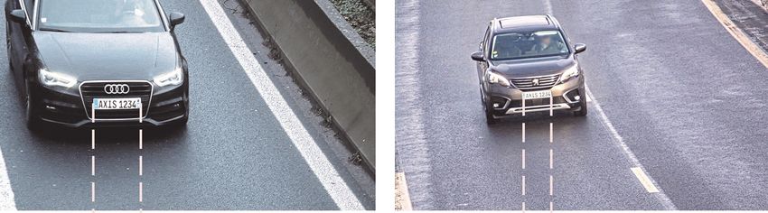
Table of Contents
    1    Summary                                       3
    2    Introduction                                  4
    3    Background                                    4
    4    Axis LPC/LPR cameras                          5
             4.1    License plate capture assistant    5
    5    Pixel density                                 6
    6    IR light                                      8
             6.1    IR reach                           8
             6.2    External IR sources                8
    7    Installation                                 10
             7.1    Camera position                   10
             7.2    Camera alignment                  11
    8    Camera settings                              13
             8.1    Max shutter time                  13
             8.2    Max gain                          14
             8.3    WDR                               14
             8.4    Tone mapping and contrast         14
    9    License plate recognition software           15
    10    Appendix 1: Optical filters                 16
             10.1 Polarization filter                 16
             10.2 IR-pass filter                      16
    11    Appendix 2: Angle between camera and car    17

2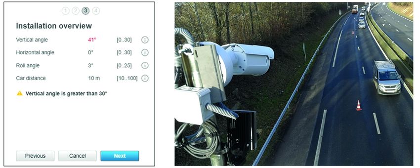
1 Summary
License plate capture (LPC) is the ability of a camera to capture readable images of license plates. It
is used in license plate recognition (LPR) systems, where the license plates are automatically detected
and read by analytics software for applications in, for example, access control, parking management, or
high-speed tolling on highways.
The detection rate and accuracy of an LPR system depends on the quality of the captured images.
Specialized LPC cameras come with default settings chosen to optimize license plate capture and minimize
the amount of configuration needed. For these cameras, everything from noise filtering and gain handling
to auto focus and day-night switching has been re-evaluated and tested in real-life outdoor traffic
scenarios. LPC requires different camera settings than most other applications, so using a dedicated LPC
camera is a way to save substantial time and effort.
High resolution is an essential part of image quality. For license plate capture, the resolution should be
high enough to resolve the individual letters and digits – at least two pixels across the smallest structure to
be resolved – but not so high that the amount of image data slows down the software analysis. Especially
when LPR software runs directly on a camera, the resolution should typically not be higher that 2 MP.
If you do not use a specialized LPC camera, lighting, installation, and camera settings require special
attention. Some of the most relevant recommendations are:
• Use artificial IR (infrared) lighting at night. It is invisible to the eye and will not blind the drivers.
• If you need to use an external light source, place it as close to the camera as possible. This is because
  license plates reflect light straight back to where it came from. Axis LPC cameras come with integrated,
  optimized IR lighting.
• Minimize the angle between the camera and the travel direction of the car, so that license plates are
  viewed head on. A total angle of less than 30° is recommended.
• Place the camera so that it captures license plates at a distance that is suitable for the expected car
  speed. Faster speeds require a longer capture distance or the system might not have time to read the
  plate before the car is out of view. Limitations imposed by the camera’s depth of field and the IR
  reach must also be taken into account.
• Limit the maximum shutter time to avoid motion blur. The recommended shutter time depends on the
  alignment of the camera as well as the speed of the vehicles.
• Limit the maximum gain of the camera to avoid overexposing the license plate.

                                                                                                               3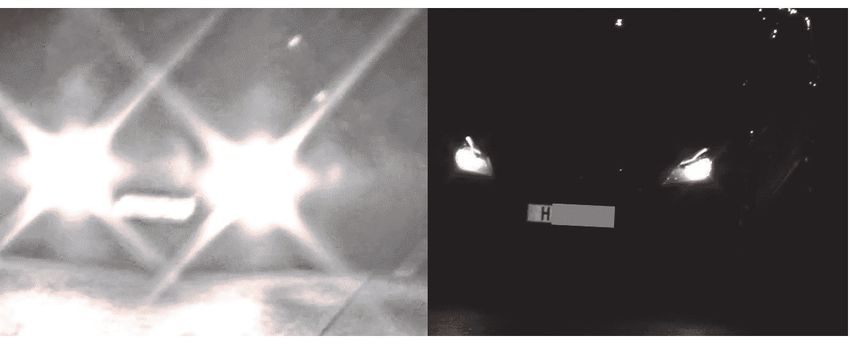
2 Introduction
License plate capture (LPC) is the ability of a camera to capture images of readable license plates. It is a
prerequisite for license plate recognition (LPR), where the license plates are automatically found and read
by analytics software.
The detection rate and accuracy of an LPR system is strongly dependent on the quality of the captured
images. As the first step in the chain, the LPC camera should deliver images of license plates with close to
perfect sharpness and contrast, day and night and in different weather conditions.
This white paper describes the key components for license plate capture, in terms of hardware choices,
installation, and configuration. Section 3 introduces specialized LPC cameras from Axis, which give
superior image quality and simplify installation and setup. Sections 5, 6, and 7 detail the necessary steps
for imaging license plates with any Axis camera.

3 Background
License plate recognition (LPR) has many applications including access control, parking management,
and high-speed tolling on highways.
LPR has been available in some form since the mid-1970s and was until recently limited to large and
expensive systems. With the rapid development of network cameras, LPR systems are getting less expensive
and more flexible, allowing for a wider range of applications.
Many names and acronyms are used for systems that are more or less equivalent to license plate
recognition: automatic license plate recognition (ALPR), automatic number plate recognition (ANPR),
automatic vehicle identification (AVI), vehicle license plate recognition (VLPR), vehicle recognition identifier
(VRI), car plate recognition (CPR), car plate reader (CPR), and so on.

Figure 1. Parts of the LPR system. 1: License plate capture, 2: Software algorithm, 3: Database or action

An LPR system consists of one or many cameras which capture images of license plates (license plate
capture). The images are processed by license plate analytics software running either directly on the
camera or on a remote server. The LPR software automatically finds and reads the license plates in real
time. Detected license plate numbers can be stored in a database for future use, or can be used to trigger
actions, for example, opening a gate.
Ideally, the LPR system should find all passing license plates and read them correctly. The image quality
from the camera is crucial for high detection rate and accuracy. No algorithm, however sophisticated, can
read a license plate from an image where the license plate is not clearly visible.

4
To successfully detect license plates the camera needs to be positioned and aligned in a rather specific way.
In addition, LPC requires different camera settings than most other applications. The default settings of a
general camera are not suitable for LPC, and the camera needs to be reconfigured. All of this makes the
installation rather cumbersome, unless you use a dedicated LPC/LPR camera.

Figure 2. Night-time license plate capture. Left: using a wrongly configured camera. Right: using a dedicated
Axis LPC/LPR camera.

4 Axis LPC/LPR cameras
Axis dedicated LPC/LPR cameras are developed with attention to the demanding conditions of traffic
installations. Components are chosen to withstand bad weather, strong winds, and temperature variations.
In Axis LPC/LPR cameras, the image optimization goes deeper than shutter time and gain settings. For these
cameras, parts of the fundamental image processing have been reconfigured specially for LPC. Everything
from noise filtering and gain handling to auto focus and day-night switching has been re-evaluated
and tested in real-life outdoor traffic scenarios.
The default settings of an Axis LPC/LPR camera are chosen to optimize license plate capture and minimize
the amount of configuration needed.

4.1 License plate capture assistant
License plate capture assistant is a feature developed by Axis to help you align and configure the camera
correctly.
The license plate capture assistant will automatically give you feedback while you align the camera.
This is possible because the camera can measure its orientation in the gravitational field. The assistant
shows you the vertical camera angle, horizontal camera angle, and roll angle continuously and displays

                                                                                                            5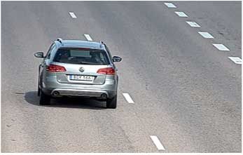
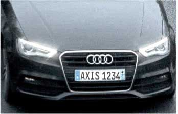
them with a warning if they are too large. It also calculates the capture distance in real time, a critical
parameter which is difficult to estimate by eye.

Figure 3. Axis license plate capture assistant will guide through the installation process and show a warning
when any angle is too large.

After the alignment is finished the camera will calculate suitable camera settings for your specific scene.
Simply press apply and the camera is optimized for capturing license plates.

5 Pixel density
For the number to be readable, a license plate should be imaged onto enough pixels on the image sensor to
resolve the individual letters and digits. To get full contrast between black lines and white spaces there
need to be at least two pixels across the smallest structure that we want to resolve in the image. For a
standard European license plate, this means that we need 74 pixels across the full width of the plate to
resolve the individual lines. This is the very minimum for resolving the number well, and most LPR software
require around 100-150 pixels over the full width of the plate.

Figure 4. A European standard license plate should cover at least 75 pixels for the letters to be imaged with
full contrast. Most LPR software require 100-150 pixels over the width of the plate.

6
From the camera perspective the number of pixels across the license plate depends on the resolution of
the image sensor and the field of view.

Figure 5. The scene width (1) depends on the camera’s field of view (2).

A varifocal lens can be zoomed in and out, which gives the freedom to choose the field of view for
a specific scene.

Figure 6. The number of pixels across the width of the license plate depends on the camera resolution and the
scene width. In this example a camera with a resolution of 1080x1920 pixels is (left:) zoomed in on one
lane (4 m wide) and (right:) zoomed out to cover almost two lanes (6.5 m wide). The license plate covers
250 pixels and 154 pixels, respectively.

The field of view depends on the format of the sensor and the focal length of the camera lens, as well as
on the lens distortion which can vary significantly between lenses.
The first table states recommended horizontal field of view, for covering one and two lanes at different
capture distances.
Table 5.1. Recommended horizontal field of view.

                   Capture distance:
                   5 m (~16 ft)        10 m (~33 ft)    20 m (~66 ft)      30 m (~98 ft)    50 m (~164 ft)
 1 lane < 4 m      33°–44°             17°–23°          9°–11°             6°–8°            3°–6°
 (~13 ft)
 2 lanes < 8 m     62°–77°             33°–44°          17°–23°            11°–15°          7°–9°
 (~25 ft)

                                                                                                             7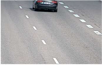
The second table lists the recommended minimum sensor resolutions to cover one and two lanes,
respectively. Note that this is for European standard license plates, and smaller license plates might
require a higher resolution.
Table 5.2. Minimum resolution.

                                                          Minimum resolution
 1 lane, width < 4 m (~13 ft)                             1 MP (HD, 720p)
 2 lanes, width < 8 m (~25 ft)                            2 MP (Full HD, 1080p)

A high resolution has the drawback that each image takes a long time for the LPR software to analyze. This
increases the risk of missing some plates when traffic is dense. When running LPR software directly on a
camera we recommend using a resolution of 2 MP or less. Consider using several cameras to cover more
lanes. Also check the recommended resolution stated in the manual of the LPR software.

6 IR light
Capturing license plates at night requires artificial lighting. Normally, infrared (IR) light is used since it is
invisible to the eye and will not blind the drivers. Most license plates are IR reflective, and IR light will
increase the visibility and contrast of the plate in darkness or cloudy weather. The IR light can come from
LEDs built into the camera, or from IR sources which are external to the camera.

6.1 IR reach
The intensity of light decreases with the distance, squared, to the light source. For a reflective object, such
as a license plate, this leads to the fact that each doubling of the distance between the light source and
the object will require a fourfold increase in IR power, in order for the object to keep the same visibility.
The longest possible capture distance for a specific setup depends on the available IR power, the IR
angle, and the light sensitivity of the camera. Axis OptimizedIR technology optimizes the IR angle of
camera-integrated LEDs for each zoom level. Axis Lightfinder maximizes the reach of the built-in IR LEDs
and reduces the need for external IR sources and additional power supplies.
Due to the short shutter times that are required for LPC, the camera will collect less light than it does
with default settings. However, the high IR reflectivity of the license plate will increase the brightness
of the plate. All in all, the specified IR reach will be reduced by about 50% when using the camera for
LPC (with a shutter time of 1/500 s). This does not apply for specialized LPC cameras, which have a short
exposure time by default and are specified accordingly.
For a general Axis camera, the IR reach is specified with default settings (usually max shutter 1/30 s) and
for non-reflective objects. For an Axis LPC camera the IR reach is specified with default settings for LPC
(usually max shutter 1/500 s or less) and for reflective license plates.

6.2 External IR sources
If the IR reach is not enough with the built-in LEDs, or if a camera does not have built-in IR LEDs, IR
sources external to the camera can be used. The light cone of the IR source should match the field of
view of the camera, at the relevant zoom level.

8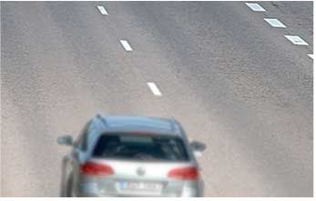
License plates are made from retroreflecting material, which means that they reflect light straight back
where it came from, no matter at which angle the light hits the plate. When using an external IR source,
the reflected IR light will come back towards the source.

Figure 7. License plates are retroreflectors. They reflect light back where it came from.

For that reason, external IR sources need to be placed close to the camera in order for the reflected light to
actually hit the camera. The brightness and contrast of a license plate in a camera image decreases quickly
as the IR source is moved away from the camera.

Figure 8. The relative contrast of a license plate 10 m away, as a function of the distance (perpendicularly to
the road) between the camera and the external IR source.

                                                                                                              9
The IR source should be aligned parallel to the camera, ensuring that the light shines on the part of the road that is in the camera’s field of view. 7 Installation Installation of a camera is often a critical step since it can be hard to re-do later. You should spend some time understanding the tradeoffs involved before you set out to do the camera mounting. Axis license plate capture assistant is a tool developed to help with installation, alignment, and fine tuning for a specific traffic scene. It can guide you by displaying relevant angles and distances in real time and warn if the alignment of the camera is not optimal. 7.1 Camera position Figure 9. The mounting height (1) and the capture distance (2) determine the vertical angle (3) between the camera and the travel direction of the car. The distance from the center of the road (4) determines the horizontal angle (5) between the camera and the travel direction of the car. It is recommended to minimize the angle between the camera and the travel direction of the car, to view the license plates more or less head on. Ideally, you should place the camera straight above the vehicles (road distance = 0 in the figure), and not too high. It is, however, a good idea to place the camera higher than the car headlights, to avoid blinding the camera with strong light. It is also recommended to avoid placing the camera close to other strong light sources, like street lamps. These could otherwise interfere with the auto exposure functionality and cause glare and reflections in the optics. Appendix 2 provides tables of calculated values for the angle between camera and car for some common mounting heights, road distances, and capture distances. 10
7.2 Camera alignment
The camera should be pointed at the road, so that the relevant lanes are centered in the image. It should
be zoomed in to cover the desired number of lanes but not more. The roll angle of the camera should be
adjusted so that the license plate is parallel to the edges of the image.

Figure 10. The camera should be aligned so that the license plate is parallel to the edge of the image.

The distance between the camera and the road part that it captures is referred to as the capture distance.
The capture distance should be chosen carefully since it will influence, in several ways, the possibility to
detect license plates. In the rest of this chapter we will discuss different parameters that affect the
choice of capture distance.

7.2.1 Depth of field
The camera needs to be well focused for the license plates to be sharp and readable. The image is, however,
sharp not only at one specific distance, but in a range of distances around the focal plane. The size of this
range is called the depth of field (DOF).

Figure 11. 1: height, 2: capture distance or focal distance, 3: focal plane, 4: depth of field. The depth of field
determines the range around the focal plane where the image is still acceptably sharp.

The DOF can be increased by reducing the size of the iris aperture. In Axis cameras, the iris setting is
automatically optimized for the current light level and usually there is no need to change it. Reducing the
iris aperture should be done with care, since it limits the low-light performance of the camera.

                                                                                                                11
7.2.2 Detectable range Figure 12. The detectable range can be limited by depth of field and resolution. 1: height, 2: capture distance (focal distance), 3: vertical angle of view The detectable range is the range of distances along the road where the license plate is visible and readable in the image. Ideally the detectable range is the full field of view of the camera, but this is not always the case. The detectable range can be limited by the depth of field of the camera, and vehicles that are far away are sometimes too small to be resolved well by the image sensor. Weather conditions such as snow, rain, and fog can severely limit the visibility at long capture distances, and hence limit the detectable range. At day time and in good weather conditions, the detectable range increases with longer capture distance. For vehicles moving at high speed it is necessary to use a long capture distance, to have enough time to read the license plate before the car exits the field of view. 7.2.3 Recommended capture distance Table 7.1. Minimum capture distance for different car speeds Car speed Recommended minimum capture distance 10 km/h (~6 mph) 4 m (~13 ft) 30 km/h (~19 mph) 7 m (~23 ft) 50 km/h (~31 mph) 11 m (~36 ft) 80 km/h (~50 mph) 24 m (~79 ft) 100 km/h (~62 mph) 27 m (~89 ft) 130 km/h (~81 mph) 30 m (~98 ft) The recommended minimum capture distance depends on the speed of the vehicles. The tabulated numbers are based on an estimated detection time of 0.2 s, which means that the LPR analytics software can analyze five frames per second. Note that the number of analyzed frames per second can vary between different LPR software and different processors, and also depends on the resolution of the images. The table is just a guide. At night, the maximum possible capture distance is often limited by IR reach. The IR reach can be improved by using more powerful external IR sources. 12
8 Camera settings
The camera settings make a large difference when it comes to license plate capture. Specialized license
plate cameras are delivered with suitable default settings and require a minimum of tuning. For other
cameras the following settings might need to be changed.
8.1 Max shutter time
Vehicles which are moving through the image will cause motion blur if the shutter time of the camera
is too long. The maximum shutter time depends on the alignment of the camera as well as the speed of
the vehicles.
Figure 13. A car moving at high speed is imaged with a shutter time of 1/30 s.
A car which is approaching the camera head on will not move transversally in the image, just get larger as
it approaches. This effect is often negligible. But as soon as there is an angle between the camera and
the direction of motion, the car will move transversally in the image at a speed which depends on the
angle. The transversal speed will cause motion blur at normal shutter times around 1/30 s, so the max
shutter time needs to be limited.
The table shows the recommended max shutter time depending on the angle between the camera and
the car travel direction, and on the speed of the vehicles. The camera angle can be estimated from
tables in Appendix 2.
Table 8.1. Recommended max shutter time depending on camera angle and car speed. 1 ms = 1/1000 s.
Car speed:
30 km/h 50 km/h 80 km/h 110 km/h 130 km/h
Camera angle (~19 mph) (~31 mph) (~50 mph) (~68 mph) (~81 mph)
5° 19.3 ms 11.6 ms 7.2 ms 5.3 ms 4.5 ms
10° 9.7 ms 5.8 ms 3.6 ms 2.6 ms 2.2 ms
15° 6.5 ms 3.9 ms 2.4 ms 1.8 ms 1.5 ms
20° 4.9 ms 2.9 ms 1.8 ms 1.3 ms 1.1 ms
25° 4.0 ms 2.4 ms 1.5 ms 1.1 ms 0.9 ms
30° 3.4 ms 2.0 ms 1.3 ms 0.9 ms 0.8 ms
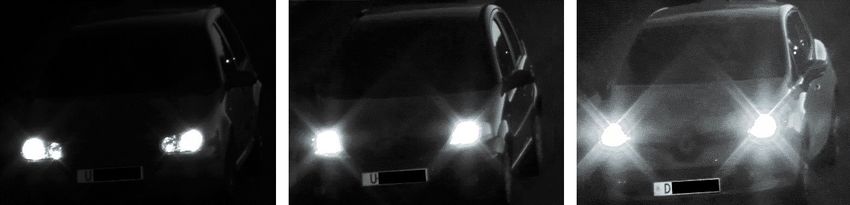
13Note that the camera will collect more light with a longer shutter time, which will increase the IR range. For example; by mounting the camera at 5° angle instead of 20° angle, the shutter time can be increased by roughly a factor four, which will double the IR range. The IR range in the data sheet of an Axis camera is specified for the default max shutter of the camera. 8.2 Max gain Since the license plate is made of reflective material it will shine up brightly when exposed to intense IR light. The surroundings will be much darker since other objects reflect much less light. The result can be that the license plate gets overexposed and impossible to read. The simplest way to avoid overexposing the license plate is to limit the max gain of the camera. Exactly how to set max gain depends on the available IR intensity, the distance to the vehicles, and the light sensitivity of the camera. Somewhere between 9 dB and 21 dB gives reasonable results when using the built-in IR of an Axis camera. Figure 14. The max gain setting will determine how the license plate is exposed at night. 8.3 WDR Wide dynamic range (WDR) comprises different techniques to increase the dynamic range of an image. WDR is very useful to bring out details which would otherwise hide in shadows, or to prevent that the camera gets "blinded" by strong light. WDR can cause motion artifacts in images of moving vehicles, depending on how WDR is implemented in a specific camera. If the camera specification does not say otherwise, we recommend that you always switch WDR off for license plate capture. 8.4 Tone mapping and contrast Tone mapping is used to enhance details in dark parts of the image. If used wrongly it can enhance glare from headlights and noise. We recommend decreasing the amount of tone mapping when the camera is used for LPC. On older cameras there is no separate tone mapping slider in the camera interface, and this setting is done via the local contrast slider. We then recommend setting local contrast to about 20%. On newer cameras where there is both a tone mapping slider and a local contrast slider, we recommend setting local contrast slightly higher, around 60%, while decreasing tone mapping to 20%. The contrast setting on the camera can be used to make the background of the image even darker at night, while bringing out the white of the license plate. If set too high it might however make the license 14
plate dark and bring out the headlights of the cars instead. We recommend increasing contrast carefully,
to about 60%, when the camera is used for LPC.

Figure 15. Tone mapping and local contrast is a tradeoff between brightness and contrast on the license
plate, and too much noise and glare in the image.

Note that for specialized LPC cameras, these settings are already optimized for LPC by default, and no
change is necessary.

9 License plate recognition software
After capturing a video stream of license plates, a special analytics software is needed to extract the license
plate numbers from the images. The performance of the LPR system depends not only on camera settings,
but also on the configuration of the LPR software. Refer to the manual for the specific software used.
LPR software can run directly on a camera, or on remote servers.
Running LPR software on a remote server can deliver large processing power, but it requires video streaming
to a remote location, which requires more network bandwidth. It is difficult to scale a server-based system
to many cameras since a large number of video streams would quickly clog the network.
Running LPR software directly on the camera means that only the license plate letters and digits need to be
sent from the camera to the central server (though the output often also contains a snapshot of the license
plate and a context view). This minimizes the requirements on network bandwidth. A distributed system
like this is easy to scale since adding a new camera does not require adding other resources to the system.
The downside of running the LPR algorithms on the camera is the limited processing power, which makes
analyzing each image more time consuming. It limits the maximum resolution that can be used, which
limits the number of lanes that can be covered by each camera. With the development of new types
of image analytics through AI and neural networks, cameras get increasingly powerful. More efficient
algorithms as well as more powerful embedded processors will reduce the time it takes to analyze each
image and make distributed systems increasingly competitive.

                                                                                                            15
10 Appendix 1: Optical filters Adding optical filters to the light path in the camera can improve the image in some specific situations. However, they often block a considerable amount of light which will worsen low-light performance and introduce more noise in the image. 10.1Polarization filter A polarization filter which is correctly aligned can reduce reflections from flat surfaces, for example the windshield of a car or the surface of the road. However, it will block 50% of all light from entering the camera, and this may have a considerable impact on image quality. The improvement of the visibility of license plates is very limited. For that reason, we do not recommend using a polarization filter for LPC. It can however be useful for general traffic surveillance, for example to improve visibility of the interior of the car. 10.2IR-pass filter An IR-pass filter blocks visible light and allows only IR light to reach the sensor. Since the license plate reflects a lot more IR light than the surroundings, the image will be darker with only the license plate shining brightly, and this can help the LPR algorithms to find the license plate. It can also be a way to improve focus at night. The filter can block light from the headlights of cars, to prevent glare and reflections in the lens. Light from LED headlights is filtered away very efficiently this way. Halogen headlights, on the other hand, emit a lot of light in the IR wavelength range, and this light is not filtered away efficiently. Figure 16. Left: the light from LED headlights is blocked by the IR-pass filter, which efficiently reduces lens glare and stray light.Right: the light from halogen headlights goes through the IR-pass filter and gives rise to lens glare.The two images were taken almost simultaneously, with identical settings and alignment, using a camera equipped with an IR-pass filter. An IR-pass filter in night mode (IR-cut filter off) can improve the detection rate and accuracy. It needs to be removed when IR is switched off (in day mode, IR-cut filter on). 16
11 Appendix 2: Angle between camera and car
The total angle between the camera and the direction of motion of the car can be calculated with the
following formulas.
Transversal distance between camera and road:

where h is the camera installation height in meters and dr is the road distance in meters.
Angle between camera and car:

where dt is the transversal distance in meters between camera and road, and dc is the capture distance
in meters.

Figure 17. The equations involve installation height h (1), capture distance dc (2), and road distance dr (4).

We recommend keeping the total angle below 30°. In the following tables the angle between the camera
and the car is calculated for some common mounting heights, road distances and capture distances.

                                                                                                                 17
Table 11.1. Camera angles at road distance 0 m. Red text indicates that the angle is too large for LPC.
Capture distance:
Height 5 m (~16 ft) 10 m (~33 ft) 20 m (~66 ft) 30 m (~98 ft) 50 m (~164 ft)
1.5 m (~5 ft) 17° 8.5° 4.3° 2.9° 1.7°
3 m (~10 ft) 31° 17° 8.5° 5.7° 3.4°
5 m (~16 ft) 45° 27° 14° 9.5° 5.7°
7 m (~23 ft) 54° 35° 19° 13° 8.0°
10 m (~33 ft) 63° 45° 27° 18° 11°
Table 11.2. Camera angles at road distance 2 m (~7 ft). Red text indicates that the angle is too large for LPC.
Capture distance:
Height 5 m (~16 ft) 10 m (~33 ft) 20 m (~66 ft) 30 m (~98 ft) 50 m (~164 ft)
1.5 m (~5 ft) 27° 14° 7.1° 4.8° 2.9°
3 m (~10 ft) 36° 20° 10° 6.9° 4.1°
5 m (~16 ft) 47° 28° 15° 10° 6.1°
7 m (~23 ft) 56° 36° 20° 14° 8.3°
10 m (~33 ft) 64° 46° 27° 19° 12°
Table 11.3. Camera angles at road distance 5m (~16 ft). Red text indicates that the angle is too large for LPC.
Capture distance:
Height 5 m (~16 ft) 10 m (~33 ft) 20 m (~66 ft) 30 m (~98 ft) 50 m (~164 ft)
1.5 m (~5 ft) 46° 28° 15° 9.9° 6.0°
3 m (~10 ft) 49° 30° 16° 11° 6.7°
5 m (~16 ft) 55° 35° 19° 13° 8.0°
7 m (~23 ft) 60° 41° 23° 16° 9.8°
10 m (~33 ft) 66° 48° 29° 20° 13°
Table 11.4. Camera angles at road distance 7 m (~23 ft). Red text indicates that the angle is too large for LPC.
Capture distance:
Height 5 m (~16 ft) 10 m (~33 ft) 20 m (~66 ft) 30 m (~98 ft) 50 m (~164 ft)
1.5 m (~5 ft) 55° 36° 20° 13° 8.1°
3 m (~10 ft) 57° 37° 21° 14° 8.7°
5 m (~16 ft) 60° 41° 23° 16° 9.8°
7 m (~23 ft) 63° 45° 26° 18° 11°
10 m (~33 ft) 68° 51° 31° 22° 14°
18T10167951/EN/M1.6/2106 About Axis Communications Axis enables a smarter and safer world by creating network solutions that provide insights for improving security and new ways of doing business. As the industry leader in network video, Axis offers products and services for video surveillance and analytics, access control, intercom and au- dio systems. Axis has more than 3,800 dedicated employees in over 50 countries and collaborates with partners worldwide to deliver customer solutions. Axis was founded in 1984 and has its headquarters in Lund, Sweden. For more information about Axis, please visit our website axis.com. ©2019 - 2021 Axis Communications AB. AXIS COMMUNICATIONS, AXIS, ARTPEC and VAPIX are registered trade- marks of Axis AB in various jurisdictions. All other trademarks are the property of their respective owners. We reserve the right to introduce modifications without notice.
You can also read