Laguerre Gaussian modes generated vector beam via nonlinear magneto optical rotation - Nature
←
→
Page content transcription
If your browser does not render page correctly, please read the page content below
www.nature.com/scientificreports
OPEN Laguerre‑Gaussian modes
generated vector beam
via nonlinear magneto‑optical
rotation
Mohsen Ghaderi Goran Abad & Mohammad Mahmoudi*
Laguerre-Gaussian (LG) beams contain a helical phase front with a doughnut-like intensity profile.
We use the LG beam to introduce a rather simple method for generation of a vector beam (VB), a
beam with spatially-dependent polarization in the beam cross section, via the nonlinear magneto-
optical rotation (NMOR). We consider the NMOR of the polarization of a linearly polarized probe
field passing through an inverted Y-type four-level quantum system interacting with a LG control
field and a static magnetic field. It is shown that the polarization of the transmitted field is spatially
distributed by the orbital angular momentum (OAM) of the LG control field, leading to generation
of the VB with azimuthally symmetric polarization distribution. We show that the polarization and
intensity distributions of the VB spatially vary by changing the OAMs of the LG control field. Moreover,
the radial index of the LG control field has a major role in more spatially polarization distributing
of the VB. It is shown that the intensity of the generated VBs in different points of the beam cross
section can be controlled by the OAM as well as the radial index of the LG control field. However,
the VB with highly spatially distributed can be generated for higher values of the radial index of LG
control field. The analytical calculations determine the contribution of the different nonlinear (cross-
Kerr effect) phenomena on the generation of the VB. We show that the VB is mainly generated via
birefringence induced by the applied fields. Finally, we use asymmetric LG (aLG) beams for making the
VBs with asymmetric polarization distribution. It is shown that by applying aLG beams, the azimuthal
symmetry of the polarization distribution breaks and the asymmetric polarization distribution can
be controlled by OAM and radial index of the aLG control field. The obtained results may find more
interesting applications in fiber/free space optical communication to enhance the capacity of the
information transmission.
Polarization is a fundamental property of light and a significant concept in optics. Specification and manipula-
tion of polarization of light plays an important role in light-matter interaction1–4. Three well-known polarization
states of a polarized light such as linear, circular, and elliptical are uniformly spatially distributed. Most past
research in polarization dealt with spatially homogeneous states of polarization, which do not depend on the
spatial location in the beam cross section. Recently, because of interesting properties and potential applications,
there has been an increasing attention to light beams with spatially-dependent polarization in beam cross sec-
tion, the so-called vector beams. Vector beams (VBs) have spatially variant polarization states with the annular
intensity distributions5. It has been demonstrated that VBs have significant features including tight f ocusing6–8
and high-resolution imaging9–11. The ability of tight focusing of VBs and generating strong longitudinal electric
field components within the focus lead VBs to be used in optical trapping and manipulation12–14. In addition,
VBs hold a large potential for data storage and quantum information p rocessing15,16. For decades, amplitude,
frequency, phase and polarization of light were the traditional degrees of freedom of light in optical commu-
nications, leading to impose some limits on the capacity of the information transmission. By introducing the
beams carrying the orbital angular momentum (OAM) with helical phase front, an additional degree of freedom
was provided for photons and hence a set of higher dimensions is presented for the high capacity information
transmission17,18. VBs have attracted significant attention in increasing the transmission capacity in optical com-
munications due to exploiting spatial polarization s tructure19. Unique properties and extensive applications of
Department of Physics, University of Zanjan, University Blvd., Zanjan 45371‑38791, Iran. * email: mahmoudi@
znu.ac.ir
Scientific Reports | (2021) 11:5972 | https://doi.org/10.1038/s41598-021-85249-8 1
Vol.:(0123456789)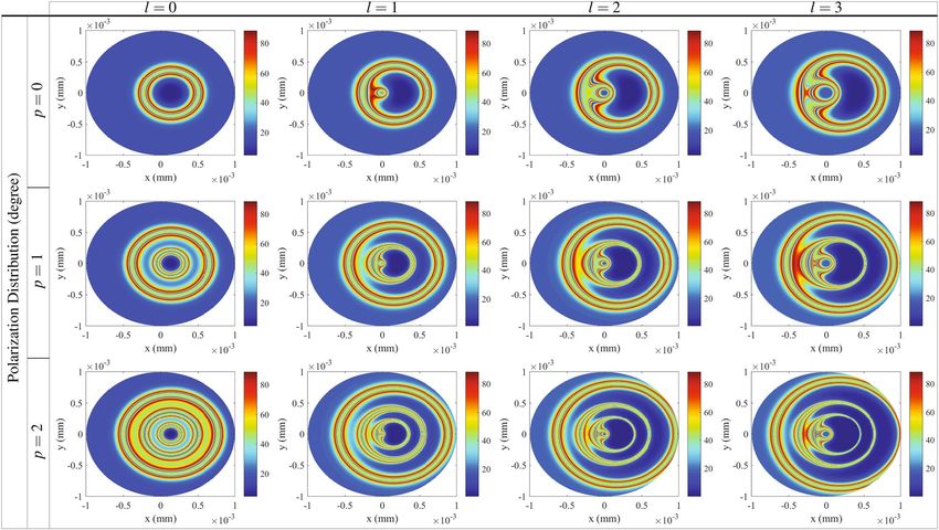
www.nature.com/scientificreports/
VBs have motivated researchers to propose various methods to generate VBs. The common methods include
using optical fi bers20,21, spatial light m
odulator22,23, arrays of concentric n
anoslits24,25 and Pancharatnam-Berry
26
phase elements . Circularly polarized fields have been often used to generate VB through metallic structures
including nanometers unit27 and metasurfaces28,29. To the best of our knowledge, linearly polarized light has
been rarely used due to the complexity of its conversion to VBs. The known mechanism of the NMOR in our
work provides a simple understanding for converting a linearly polarized light to a controllable VB. Moreover,
the volume of optical devices in the previously presented methods is large with a complex experimental setup,
while the NMOR has generally a rather simple setup with stable output.
On the other hand, polarization rotation of a polarized light has been receiving much attention for a wide
variety of its applications for many decades. It is well-known that when a linearly polarized light30 or even
elliptically polarized light31 pass through an anisotropic medium, the light polarization plane experiences a
rotation. NMOR arises when the polarization plane of light is rotated by a medium subjected to a magnetic field
and laser fields. In fact, the difference between the refractive indices of the circular components of the linearly
polarized light is the basis of the asymmetry made by the magnetic or optical fields. NMOR has found a large
number of applications32 and been used as a practical and useful method in optical filters33,34, optical limiting35,36,
magnetometry37–39 and laser-frequency s tabilization40.
In the past three decades, of among all vortex beams, Laguerre-Gaussian (LG) beams are the most interest-
ing due to their unique features in a wide variety of a pplications41–44. LG modes are obtained from solving the
paraxial Helmholtz equation in cylindrical coordinates. The azimuthal phased dependence (eilφ ) of the LG
modes leads to carrying OAM by lℏ per photon45, where l is an integer. LG modes have a helical wave front with
a quantized 2πl azimuthal phase change of the electric field. Moreover, the phase singularity of the LG modes
on the beam axis dictates zero intensity at the beam c enter46, leading the intensity pattern of the LG modes to
take the form of a doughnut or even concentric rings. It has been demonstrated that the characteristics of the
optical phenomena can be influenced by the LG beams47–49. Mahmoudi et al. showed that the use of LG beams
narrowed the linewidth of the optical spectrum of the multi-photon resonance phenomena50. However, what
caught our eye was the observation of the spatial dependence of some optical phenomena like electromagneti-
cally induced t ransparency51 and e ntanglement52 using vortex light beams. It inspired us to impart the potential
of LG modes to the NMOR for obtaining the distribution of polarization, leading to generate VBs. In this regard,
we implement the nonlinear magneto-optical rotation (NMOR) using the LG beams as a rather simply novel
technique to the generation of VBs.
In this paper, we propose the NMOR as a new simple technique to generate VBs and control their spatial
polarization distribution. The aim of our work is to simplify the generation and control of VBs with respect
to the previous works. The presented scheme includes the NMOR of a linearly polarized probe field passing
through an inverted Y-type four-level quantum system subjected to a LG control field and a static magnetic
field. It is demonstrated that the OAM of the LG control field makes the polarization of the transmitted field to
be spatially distributed, leading to the generation of VBs with azimuthally symmetric polarization distribution.
We show that by increasing the magnitude of the OAM, the spatial distribution of VBs varies and their polari-
zations are more distributed in cross section of the VBs. It is illustrated that the radial index of the LG control
beam has a major role in changing the polarization directions and the spatially distribution of VBs. In addition,
we demonstrate that the intensity of the generated VBs can be simply controlled by the characteristics of the LG
beam. However, VBs with more higher intensity regions are generated by increasing the magnitude of the radial
index of the LG beam. Our analytical results show the role of the direct response and multi-photon nonlinear
cross-Kerr effect in generation of the VBs. We demonstrate that the polarization rotation in different points of
the VB cross section is related to the major contribution of the birefringence induced in the system. Finally, we
exploit asymmetry LG (aLG) beams and breaks the symmetry of the polarization distribution of the VBs. It is
shown that by applying the aLG control field, azimuthally asymmetric polarization distribution is achieved so
that the asymetric polarization distribution can be controlled by OAM and radial index of the aLG control field.
Generating and controlling the spatial distribution of VBs in our work provide an excessive capacity in optical
communicating and networking.
Model and theoretical method
The realistic quantum system of interest is shown in Fig. 1. We consider an inverted Y-type four-level quantum
system, which can be derived from 5S1/2 − 5P3/2 − 5D5/2 lines of 87 Rb atoms in a vapor medium. Two states
|1� = |5S1/2 , (F = 2, mF = −1)� and |2� = |5S1/2 , (F = 2, mF = +1)� are the degenerate ground states. The state
|3� = |5P3/2 , (F = 3, mF = 0)� is set as intermediate state and the state |4� = |5D5/2 , (F ′ = 2, mF ′ = 0)� is assumed
as the excited state. Here, F and F ′ are the quantum numbers of the total angular momentum and also mF denotes
the magnetic quantum number of the corresponding states. In the considered system, the Doppler effect due
to the motion of atoms is ignored. A static magnetic field is applied to the system, which lifts the degeneracy of
the ground states by ℏ�B = ms gs µB B (Zeeman splitting) where µB is Bohr magneton, gs is Lande’ factor and
ms = ±1 is the magnetic quantum number of the corresponding sublevel of the ground state. A linearly polarized
weak probe field E� = x̂Ep exp[−i(ωp t − kp z)] + c.c with a wavelength of 780.238 nm is applied to the medium
parallel to the static magnetic field satisfying the Faraday geometry53. A linearly polarized field is composed of a
right- and left-circularly polarized component. Then, right-(left-) circular component of the probe field excites
the transition |3� ↔ |1�(|3� ↔ |2�) with Rabi frequency �p+ = (µ � 31 · ǫ�+ )E+ /ℏ (�p− = (µ � 32 · ǫ�− )E− /ℏ ), so that
√
E+ = E− = Ep / 2 and |µ�41 | = |µ�31 |. Also, a linear polarized LG control field with a wavelength of 775.978 nm
couples the intermediate state |3� to the excited state |4� with Rabi frequency �c = (µ � 43 · ǫ�c )Ec /ℏ . Here, ǫc is the
Scientific Reports | (2021) 11:5972 | https://doi.org/10.1038/s41598-021-85249-8 2
Vol:.(1234567890)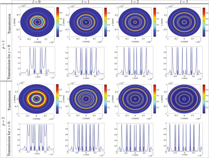
www.nature.com/scientificreports/

                                  Figure 1.  Schematic diagram of an inverted Y-type four-level quantum system. The system is driven by a LG
                                  control field with Rabi frequency c , a left- and right-circularly polarized fields with Rabi frequencies p− and
                                  p+ , respectively, derived from a linearly polarized probe field.

                                  coupling field unit vector and ǫ± are the right- and left-rotating unit vector and Ei (i = ±, c) are the amplitudes
                                  of the applied fields. Moreover, µij is the dipole moment vector for the transitions |i� to |j�. The LG control field
                                  in the cylindrical coordinates has the form
                                                                                         √ |l|
                                                                                  wG       2r         |l|      2  2
                                                              Ec (r, ϕ) = E0c √                  × Lp (x)e−r /wLG eilϕ ,                            (1)
                                                                                 |l|!wLG wLG

                                  where E0c , l and p denote the amplitude, OAM and radial index of the LG control field, respectively. wG and wLG
                                                                                     |l|
                                  are the Gaussian and LG beam waist, respectively. Lp (x) with x = 2r 2 /wLG
                                                                                                           2 is the Laguerre polynomial, which
                                  is written as

                                                                             |l|      ex x −|l| d p  |l|+p −x
                                                                           Lp (x) =                  x     e     .                                 (2)
                                                                                         p! dx p

                                     In the interaction picture, the Hamiltonian of the system in the dipole and rotating wave approximations is
                                  written as

                                                VI = −ℏ(�∗p+ ei(�p+ +�B )t |3��1| + �∗p− ei(�p− −�B )t |3��2| + �∗c ei�c t |4��3|) + h · c.,       (3)
                                  where �p+ = ω31 − ωp+, �p− = ω32 − ωp− and �c = ω43 − ωc are the detunings of the applied fields from
                                  the corresponding atomic transitions. The terms ωp+, ωp− and ωc are the frequencies of the right-, left-circular
                                  components and control field, respectively. Also, ωij is the |i� ↔ |j� atomic transition frequency.
                                     The density matrix equations of motion are given by
                                                   ρ̇11 = γ31 ρ33 − i�∗p+ ρ13 + i�p+ ρ31 ,
                                                   ρ̇22 = γ32 ρ33 − i�∗p− ρ23 + i�p− ρ32 ,
                                                   ρ̇44 = −γ43 ρ44 − i�c ρ43 + i�∗c ρ34 ,
                                                   ρ̇31 = −[γ3 /2 + i(�p+ + �B )]ρ31 + i�p− ρ21 + i�c ρ41 + i�∗p+ (ρ11 − ρ33 ),
                                                   ρ̇41 = −[γ43 /2 + i(�c + �p+ + �B )]ρ41 + i�∗c ρ31 − i�∗p+ ρ43 ,
                                                                                                                                                   (4)
                                                   ρ̇32 = −[γ3 /2 + i(�p− − �B )]ρ32 + i�∗p+ ρ12 + i�c ρ42 + i�∗p− (ρ22 − ρ33 ),
                                                   ρ̇42 = −[γ43 /2 + i(�c + �p− − �B )]ρ42 + i�∗c ρ32 − i�∗p− ρ43 ,
                                                   ρ̇43 = −[(γ3 + γ43 )/2 + i�c ]ρ43 − i�p− ρ42 − i�p+ ρ41 + i�∗c (ρ33 − ρ44 ),
                                                   ρ̇21 = −i(�p+ − �p− + 2�B )ρ21 − i�p+ ρ23 + i�p− ρ31 ,
                                                   ρ̇33 = −(ρ̇11 + ρ̇22 + ρ̇44 ),

Scientific Reports |   (2021) 11:5972 |                https://doi.org/10.1038/s41598-021-85249-8                                                      3

                                                                                                                                                Vol.:(0123456789)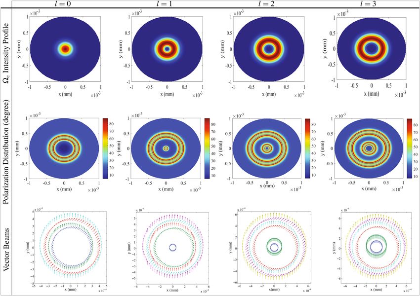
www.nature.com/scientificreports/
where γ3 = γ31 + γ32 . Parameter γ43 is the decay rate from the excited state |4� to the intermediate state |3� and
γ3i = γ (i = 1, 2) is the decay rate of the intermediate state |3� to the ground state |i�. The susceptibility of the
medium corresponding to the right- and left-circular components of the linearly polarized probe field is given by
α
χ± = S± , (5)
4πkp
where kp is the wave number of the probe field and αl = 4πkp dµ2 N/ℏγ is the field absorption at resonance,where
N and d are the atomic density number and length of the medium, respectively. We introduce S± as normalized
susceptibility
ρ31 γ31 ρ32 γ32
S+ = , S− = . (6)
�p+ �p−
ρ31 and ρ32 are the transition coherences, which can be obtained from Eq. (4). The term S± is a complex quantity,
which its real (imaginary) part indicates the dispersion (absorption) of the circular components of the probe
field. Now, let us calculate the NMOR angle of the polarization direction of the transmitted VBs. It should be
noted that the polarization direction of the input probe field is assumed in x direction. In experimental works,
the polarization rotation can be measured using a ŷ-polarized analyzer permitting only the polarized field in ŷ
direction. Intensity of transmission of VB with polarization direction in y (Ty ) and x (Tx ) is given b
y30
|(Ep(out) )y |2 1
Ty = = |exp[iαlS+ /2] − exp[iαlS− /2]|2 (7)
|Ep(in) |2 4
|(Ep(out) )x |2 1
Tx = = |exp[iαlS+ /2] + exp[iαlS− /2]|2 (8)
|Ep(in) |2 4
Thus, the NMOR angle of the polarization direction of the VBs is
φ = tan−1 [ Ty /Tx ]. (9)
In general, rotation of the polarization direction of a polarized light happens due to birefringence and dichro-
ism induced in the system. Difference between dispersion (absorption) of the circular components of the probe
field leads to inducing the birefringence (dichroism) in the system. For the case that Re[S+ ] � = Re[S− ] and
Im[S+ ] = Im[S− ] ≈ 0 , the Polarization direction of light is rotated merely due to the birefringence. On the
contrary, dichroism is the dominant phenomenon when Im[S+ ] � = Im[S− ] and Re[S+ ] = Re[S− ] ≈ 0.
Results and discussion
Now, we are going to study the distribution of the polarization of the transmitted probe field and generation
of VBs through the NMOR by numerically solving the Eq. (4) in steady state condition. It is well known that
the transmission of the probe field passing through the medium can be affected by intensity of the coupling
field via the nonlinear cross-Kerr effect. We are going to use this fact to generate the light beams with spatially-
dependent polarization in the beam cross section. Throughout the results, it is assumed that − = + = p
and p− = p+ = p . Also, the parameters used are scaled with γ which is taken as γ = 2π × 6 MHz for
D2 transition of 87Rb. Here, we are interested in investigating the NMOR angle of the linearly polarized probe
field in the cross section of the transmitted probe field which is called the spatial polarization distribution.
Figure 2 shows the intensity profile of the Gaussian and different modes of the LG control field (first row), the
spatial polarization distribution of the transmitted field (second row) in unit of degree and a schematic of the
corresponding VBs (third row) as a function of x and y for the Gaussian and different modes of the LG control
field. Used parameters are �0c = (µ � 43 · ǫ�c )E0c /ℏ = 18γ , �p = 0.01γ , �B = 10γ , αl = 140γ , c = 0, p = 0,
wG = 1 mm, wLG = 270 mm and p = 0. The first row of Fig. 2 shows the intensity distribution of the Gaussian
and LG control field cross section affected by the OAM. Because of the spatially-dependent intensity profile of
the LG control field, it is expected that the LG control field induces the spatially-dependent transmission for
the right- and left-circular components of the probe field. The second row describes that the polarization of the
transmitted probe field is spatially distributed and the spatially homogeneous state of polarization of the probe
field switches to the VB. It is seen that the polarization direction of the generated VB experiences the NMOR
form zero to 90° at different points of a cross section of the probe beam. For the Gaussian control field, there are
only two rings with perfect NMOR angle accompanied by a large area with negligible rotation angle at the center
of beam shown in first column of Fig.2. Moreover, the rest area in the cross section possesses spatially different
distribution of the NMOR angle. Now, we apply the LG control field containing OAM with different topological
charges, i.e l = 1 (second column), l = 2 (third column) and l = 3 (fourth column) in Fig. 2. Applying different
modes of the LG control field generates the various spatial distribution of the polarization. It is observed that
four rings appear with perfect NMOR angle and the rest area has differently spatial distribution of the polariza-
tion. The new two rings appeared nearer the center of the profiles do not exist in the case of the Gaussian control
field. Note that the inner ring for l = 1 in the second column is not shown because of its smaller radius with
respect to the other three rings. It is shown that by increasing the OAM of the LG control field, the polarization
distribution spatially varies in the cross section of the probe field and is extended to larger radii. These results
Scientific Reports | (2021) 11:5972 | https://doi.org/10.1038/s41598-021-85249-8 4
Vol:.(1234567890)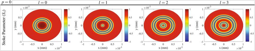
www.nature.com/scientificreports/
Figure 2. The intensity profile of the Gaussian and LG control field (first row), polarization distribution of the
transmitted probe field (second row) in unit of degree and a schematic of the generated VBs (third row) as a
function of x and y for Gaussian field l = 0 and different modes of LG control field l = 1, l = 2 and l = 3. Used
parameters are �0c = 18γ , �p = 0.01γ , �B = 10γ , αl = 140γ , c = 0, p = 0, wG = 1 mm, wLG = 270 mm
and p = 0.
are in good agreement with increasing the radius of maximum optical intensity for higher LG m odes54. A sche-
matic of the corresponding VBs is presented in the third row of Fig. 2. Every vector stands for a local electric
field direction at a cross section of the probe field. Since the polarization direction of the input field has been
assumed in x direction, the angle between any vector beam and axis x indicates the amount of the NMOR of the
polarization direction of the linearly polarized probe field. Figure 2 clearly shows that although the input probe
field has a homogeneous polarization in x direction, the output probe field after passing through the medium
has a various polarization in different points of the cross section of the probe field, leading to generation of the
VB. Thus, the generation, spatial distribution and polarization directions of the VBs depend on the topological
charge of the LG control field.
To clarify the mechanism of the MORs happened in Fig. 2, we are interested in investigating the absorption
and dispersion spectrum of the circular components of the input field. The absorption (first row) and disper-
sion (second row) of the right- (solid) and left-(dashed) circular components of the transmitted probe field are
depicted in one-dimension x in Fig. 3. It is shown in the first row that the absorptions of the circular components
of the linearly polarized probe field are approximately the same in most regions of the VB’s cross section. There
are only two peaks in absorption spectrum for the Gaussian beam and four peaks for different modes of the LG
control fields, while the absorption is negligible in the rest regions for both circular components. Although there
is a significant absorption in the peaks for circular components, the amount of their difference is still negligible.
The second row of Fig. 3 shows that the dispersion is largely different in most areas of the VB’s cross section
for the right- and left-circular components. Difference dispersion of the circular components accompanied by
their negligible absorption difference leads to inducing the birefringence in all parts of the cross section. Thus,
the MOR happened at different points of the cross section is mainly due to birefringence induced in the system.
Let us study the intensity of the output VB, which has a major role in VB transmission. In this regards, the
y-polarized transmission distribution of the generated VB is depicted in the first row of Fig. 4 as a function of x
and y for different values of the OAM, i.e. i.e l = 0 (first column), l = 1 (second column), l = 2 (third column)
and l = 3 (fourth column). The taken parameters are those used in Fig. 2. It is shown that the generated VBs are
transmitted with different intensity profiles, depending on the OAM of the LG control field. An investigation on
Scientific Reports | (2021) 11:5972 | https://doi.org/10.1038/s41598-021-85249-8 5
Vol.:(0123456789)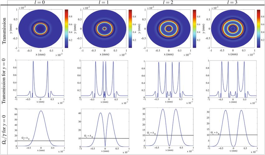
www.nature.com/scientificreports/

                                            Figure 3.  The Absorption (first row) and dispersion (second tow) of the right-(solid) and left-(dashed) circular
                                            components of the linearly polarized probe field in one dimension (x). The used parameters are those taken in
                                            Fig. 2.

                                            Figure 4.  The y-polarized intensity distribution of VBs related to the Fig. 2 as a function of x and y (first row),
                                            the perspective of transmission in y = 0 (second row) and the evolution of the Rabi frequency of the LG control
                                            field for y = 0 (third row). The used parameters are those used in Fig. 2.

                                            the first row of the Fig. 4 displays various transmissions for different radii of the VBs cross section, so that it can
                                            be found the transparent rings with locations depending on the OAM of the LG control field. Figure 4 shows that
                                            the transmissions behavior in four higher NMOR rings, displayed in Fig. 2, are physically different and only two
                                            rings with higher intensity of transmissions appear in the transmission profile. The second row in Fig. 4 shows
                                            the perspective of transmission in y = 0. One can see the location of the rings with a transparent window in cross
                                            section of the generated VB. Since the higher transmission in y direction appears only in a single ring (for p = 0,
                                            l = 0) and two rings (for p = 0, l = 0), the birefringence is dominant in generation of the NMOR in these rings.
                                            Now, we are interested in determination of the two other higher NMOR rings, displayed in Fig. 2, which do not
                                            appear in the transmission profile. The lost high NMOR rings are related to the location of the absorption peaks
                                            shown in Fig. 3. As mentioned above, the maximum absorption is equal for both circular components, while

          Scientific Reports |   (2021) 11:5972 |                 https://doi.org/10.1038/s41598-021-85249-8                                                     6

Vol:.(1234567890)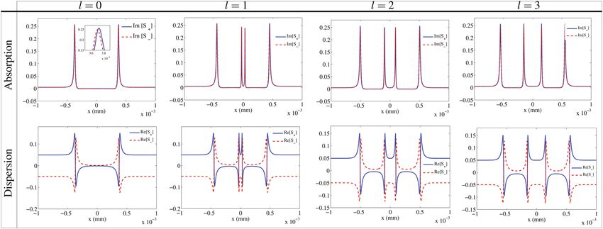
www.nature.com/scientificreports/
Figure 5. Profile of S1 of Stokes parameters as a function of x and y for Gaussian and different modes of LG
modes. The used parameters are those used in Fig. 2.
their corresponding dispersion is largely different. Despite the large absorptions, the high NMOR occurred in
those rings are due to mere birefringence which can be seen in Fig. 2. In the third row of Fig. 4, the evolution of
the Rabi frequency of the LG control field is depicted for y = 0. A line is seen in the diagrams that corresponds
to c =
B, which is crucial. Applying a static magnetic field causes the detuning of the transitions correspond-
ing to the right- and left-circular components of the probe field to be shifted by + B and − B , respectively. In
addition, the AC stark effect due to the LG control field applies an additional detuning value, equal to − c , to
the ±55. Finally, we have + → + + B −
c and − → − − B −
c . Since the circular components
of the probe field in the absence of the static magnetic and control fields are assumed in resonance, the one-
photon transition for the right- and left circular components, after applying fields, occurs only at c =
B and
c = −
B , respectively. It is well-known that the optical properties of a non-closed interaction loop system
do not depend on the sign of the control field, so the absorption is the same for c = ±
B56. Fortunately, our
analytical and numerical results show that the maximum absorption of both circular components occurs around
c =
B. In this regard, the exact locations of the maximum NMOR in the equal absorption peaks can be speci-
fied by the intensity profile of the LG control field. As a result, the condition c =
B determines the position
of the perfect NMOR rings induced by mainly birefringence in absorption peaks of circular components, as
shown in the third row of Fig. 3. So the contribution of birefringence in all rings with perfect NMOR, appeared
in Fig. 2, is dominant and the dichroism has a negligible contribution in the generation of the VB. It should be
noted that since each intensity for p = 0 and l = 0 is observed in two radii of the LG field’s intensity profile,
one can see that the inner and outer rings in the second row of Fig. 2 are generated in the rings with maximum
absorption of circular components, while two others happen in transparency windows. The inner (outer) ring
with the maximum NMOR for p = 0 and l = 0, corresponding to the higher (lower) control field intensity, is
established in the transparent window (absorption peak).
Now, we use Stokes parameters to have another insight into understanding the state of polarization in the cross
section of the generated VBs. Stokes parameters based on the electric field amplitude are a useful tool to describe
and measure the optical polarization57,58. The normalized Stokes parameters are given with the four elements by59
S = (1 S1 S2 S3 )Trans . (10)
√ √
S1 = (Tx − Ty )/S0, S2 = (2 Tx Ty cosδ)/S0 and S3 = (2 Tx Ty sinδ)/S0, where S0 = Tx + Ty and δ = 0 for
linear polarization. The superscript Trans stands for the transpose of the matrix. In our work, Ty and Tx are the
intensities of the transmission in y and x directions, respectively. Since the polarization of linearly polarized
transmitted field makes an angle φ with x direction, S1 and S2 lead to S1 = cos 2φ and S2 = sin 2φ , respectively.
So, it is expected that the parameter S1 represents the magnitude of NMOR angle in VB’s cross section. In Fig. 5,
the profile of S1 is presented as a function of x and y for Gaussian and different modes of LG modes. The posi-
tions with values of − 1 and 1 show the positions of the perfect NMOR and the initial polarization, respectively,
which are in good agreement with the results of the second row of Fig. 2.
Here, we are going to present the analytical expressions to understand the physics of the phenomena and the
role of the different parameters in the evolution of the system. The analytical solutions for the transition coher-
ences ρ31 and ρ32 in the weak probe field approximation are given by
2Z�4B 2�2B (iA + Z)�2c 2iA�4c
ρ31 = �p+ + �p+ + �p+ (11)
D D D
2ZA2 �2B i�2 (4γ + �B )�2c A∗ (1 + 2i)�4c
ρ32 = �p− + B �p− + �p− , (12)
D D D
where D = (A − i�c )(−iA + �c )(4ZA∗ �2B + ((8 − 2i)γ �B − �2B )�2c + (1 + 4i)�4c ) , A = γ + i�B and
Z = γ + iA∗. The coherence terms corresponding to the transitions |1� ↔ |2�, |1� ↔ |4� and |2� ↔ |4� do not
play major roles and have been dropped in calculation of Eqs. (11, 12). The first terms are the direct responses
of the medium to the circular components of the probe field. The second terms stand for the cross-Kerr effect
p+ c ∗c p− ∗c c
through the three-photon transitions |1� −−→ |3� −→ |4� −→ |3� and |2� −−→ |3� −→ |4� −→ |3� for the right-
and left-circular components of the probe field, respectively. The third terms correspond also to the cross-Kerr
Scientific Reports | (2021) 11:5972 | https://doi.org/10.1038/s41598-021-85249-8 7
Vol.:(0123456789)www.nature.com/scientificreports/
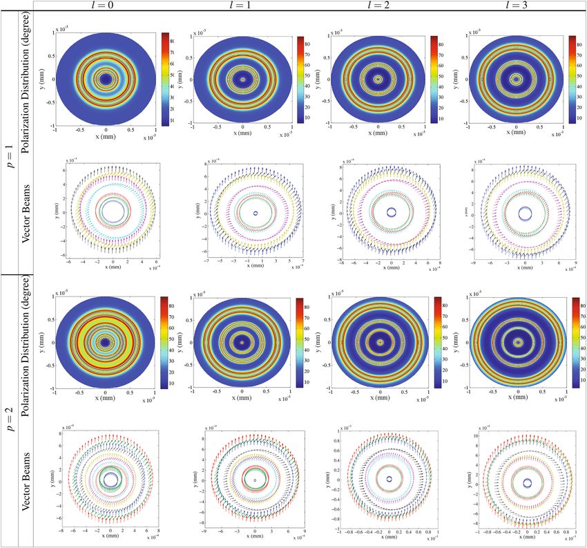
Figure 6. Polarization distribution of the transmitted probe field (first and third rows) in unit of degree and a
schematic of the generated VB (second and fourth rows) as a function of x and y for Gaussian field l = 0 and
different modes of LG control field l = 1, l = 2 and l = 3 for the radial indices p = 1 and p = 2 of the LG field.
The other parameters are those used in Fig. 2.
p+ c ∗c c ∗c
effect, but through the five-photon transitions for the right- |1� −−→ |3� −→ |4� −→ |3� −→ |4� −→ |3� and
p− c ∗c c ∗c
for the left- |2� −−→ |3� −→ |4� −→ |3� −→ |4� −→ |3� circular components of the probe field. Equations (11)
and (12) are in good agreement with the numerical results and demonstrate the contribution of the different
nonlinear effects on the obtained NMOR.
Now, we are going to investigate the effect of the radial index p on the generation of VBs. Overall, the
effect of p has been rarely discussed on the optical phenomena60. However, it has been proved that considera-
tion of p increases the information degree of freedom, allowing multi-dimensional quantum computing and
encryption61–63. Figure 6 displays the effect of p on the spatial distribution of the polarization direction of VBs
in unit of degree for p = 1 (first and second rows) and p = 2 (third and fourth rows) for different values of the
OAM, i.e. l = 0 (first column), l = 1 (second column), l = 2 (third column) and l = 3 (fourth column) as a func-
tion of x and y. The other parameters are those used in Fig. 2. It is seen that for p > 0 and l = 0, the central part
of the profiles has the least NMOR similar to the results of the Gaussian control field, but with a smaller radius
than the case of p = 0. However, the rest of the space possesses different polarizations so that they spatially
vary by increasing the value of p. It is demonstrated that for p > 0 and higher modes of the LG control field, the
Scientific Reports | (2021) 11:5972 | https://doi.org/10.1038/s41598-021-85249-8 8
Vol:.(1234567890)www.nature.com/scientificreports/
Figure 7. The y-polarized intensity distribution of the VB as a function of x and y for different OAMs of the
radial indices p = 1(first row) and p = 2 ( third row) of the LG control field. The corresponding perspective of
the transmission of the generated VBs in y = 0 for p = 1 (second row) and p = 2 (fourth row).
new regions which are limited between rings with higher NMOR angle are created with various polarizations
distribution. Also, the number of these new regions increases by increasing the value of p. This implies that the
generated VB contains a polarization distribution with more spatial variation than the case of p = 0. Moreover,
it is seen that by increasing the magnitude of p, the number of the rings with higher NMOR angle increases,
leading to the generation of the VB with more nearly complete NMOR rings. It is worth to note that for any value
of p, polarization distribution of the transmitted VBs still varies by increasing the OAM and extends to larger
radii. A schematic of the wide polarization direction range of the generated VBs are presented in Fig. 6 for p = 1
(second row) and p = 2 (fourth row). The effect of p on the generation and polarization distribution of VBs can
be seen in these schematic figures. Considering the direction of the initial polarization in x direction, one can
see the amount of the NMOR angle in corss section of the transmitted VBs. It is resulted that p has a major role
in generation and spatial distribution of VBs with a wide variety of new polarization directions induced by the
NMOR technique. Thus, the radial index p provides extra capacity in space for optical communications.
Here, we are going to show the intensity of the generated VB affected by p, which is a significant feature of
VBs. Intensity of y-polarized transmission of VBs related to the radial indices p = 1 (first row) and p = 2 (third
row) for different modes of the LG control field is presented in Fig. 7. It is shown that the generated VB has a
certain intensity in different points of the space, and this intensity covers a wide range from the lowest to the
highest intensity. Figure 7 shows that the intensity distribution of VBs can be also controlled by p. To clarify the
obtained results, we display a corresponding perspective of the transmission of the generated VBs in y = 0 for
p = 1 (second row) and p = 2 (fourth row). The transmission peaks stand for the higher NMOR rings induced
by the birefringence. So, other higher NMOR rings depicted in Fig. 6 are generated by the dichroism induced
in the system. An investigation on Fig. 7 shows that p plays an important role in increasing the intensity of VBs.
It is worth noting that the VBs with high intensity rings are generated in larger radii as p increases. Thus, the
radial index p has a significant effect on the intensity distribution of the transmitted VBs. The generated VB in
our results have an azimuthally symmetric of the polarization distribution which makes the work fall short on
impact. Here, we are interested in breaking the azimuthally symmetric using non-coaxial LG beams which is
Scientific Reports | (2021) 11:5972 | https://doi.org/10.1038/s41598-021-85249-8 9
Vol.:(0123456789)www.nature.com/scientificreports/
Figure 8. Polarization distribution of the VBs in unit of degree as a function of x and y for different OAMs of
the radial indices p = 1(first row), p = 2 (second row) and p = 3 (third row) of the aLG control field. the shift
parameter a is equal to a = 0.5wLG. Other parameters are those taken in Fig. 2 .
odes64. Assuming a shift by a along
made by imposing a transverse shift in the vortex center of symmetrical LG m
the positive x direction, Eq. (1) is transformed to the aLG beams amplitude a s65
√
|l|
wG 2r |l| 2 2 2
Ec (r, ϕ) = E0c √ × Lp (x)e−(r +a −2arcosϕ)/wLG eilϕ , (13)
|l|!wLG wLG
where x = 2(r 2 + a2 − 2arcosϕ)/wLG
2 . The polarization distribution of the generated VBs in unit of degree is
shown in Fig. 8 for p = 0 (first row), p = 1 (second row) and p = 2 (third row) for different OAMs of the aLG
control field as a function of x and y. Through the results, a = 0.5wLG and the other parameters are those taken in
Fig. 2. It is seen that the azimuthal symmetry of the polarization distribution of the VBs is broken using aLG. For
l = 0, the polarization distribution is just shifted without any asymmetry. By applying different modes of the aLG
control field, the polarization is no longer azimuthally symmetric in the cross section of the VBs. By increasing
the value of the OAM, it is shown that the polarization distribution becomes more asymmetric. Moreover, the
radial index of the aLG control fields is another useful parameter in increasing the asymmetry of the polariza-
tion distribution. It should be noted that since the generated VB is due to the effect of the intensity profile of the
LG beam and the helical phase front structure via interference does not have any contribution to the generated
VB, it cannot be destroyed during propagation through the medium. Let us calculate the Fresnel’s diffraction
integral to investigate the stability of the generated VBs during its propagation in free space after leaving the
medium. Our calculations confirm that the propagation of the generated VBs does not affect the polarization
distribution, leading to the stable VBs.
Conclusion
In summary, the LG beam was presented to generate and control VB via NMOR. Our scheme was aimed to
simplify the generation and control of VBs with respect to the previous methods. The basis of our work was
the NMOR of the polarization direction of a linearly polarized probe field passing through an inverted Y-type
four-level quantum system subjected to a LG control field and a static magnetic field. It was shown that the
polarization of the transmitted field varies spatially by the OAM of the LG control field, leading to an azimuth-
ally symmetric polarization distribution and generation of VB. In addition, we found that the intensity of VBs
can be easily controlled by the characteristics of the LG control field. We demonstrated that the radial index p
has a major role in more spatially distribution of VB with different polarization directions; so that by increasing
p, the VB with more number of higher NMOR rings were generated with higher intensity of transmission. The
contribution of the direct response of the medium, as well as the different nonlinear cross-Kerr effect, in genera-
tion of the VBs was determined by the analytical results. Besides, we showed that the polarization distribution of
Scientific Reports | (2021) 11:5972 | https://doi.org/10.1038/s41598-021-85249-8 10
Vol:.(1234567890)www.nature.com/scientificreports/
VB is due to mainly birefringence induced in the system. Finally, aLG field was used for breaking the symmetry
of the polarization distribution of the VBs to increase their efficiency. It was shown that by applying the aLG
control field, azimuthally asymmetric polarization distribution is achieved and the degree of asymmetry can be
controlled by the OAM and radial index of the aLG control field. The simple generation method, controllably
spatial distribution and intensity profile of VBs in our work provide an excessive capacity in optical communica-
tion and optical networking.
Received: 2 July 2020; Accepted: 23 February 2021
References
1. Huard, S. Polarization of Light (Wiley, 1997).
2. Klyshko, D. N. Polarization of light: Fourth-order effects and polarization-squeezed states. J. Exp. Theor. Phys 84, 1065–1079 (1997).
3. Damask, J. N. Polarization Optics in Telecommunications (Springer, 2005).
4. Kumar, A. & Ghatak, A. Polarization of Light with Applications in Optical Fibers (SPIE Press, 2011).
5. Zhan, Q. Cylindrical vector beams: from mathematical concepts to applications. Adv. Opt. Photonics 1, 1–57 (2009).
6. Zhan, Q. & Leger, J. R. Focus shaping using cylindrical vector beams. Opt. Express 10, 324–331 (2002).
7. Yu, P. et al. Co-enhancing and-confining the electric and magnetic fields of the broken-nanoring and the composite nanoring by
azimuthally polarized excitation. Opt. Express 21, 20611–20619 (2013).
8. Bauer, T., Orlov, S., Peschel, U., Banzer, P. & Leuchs, G. Nanointerferometric amplitude and phase reconstruction of tightly focused
vector beams. Nat. Phys. 8, 23–27 (2014).
9. Biss, D. P., Youngworth, K. S. & Brown, T. G. Dark-field imaging with cylindrical-vector beams. Appl. Opt. 43, 470–479 (2006).
10. Chen, R., Agarwal, K., Sheppard, C. J. & Chen, X. Imaging using cylindrical vector beams in a high-numerical-aperture microscopy
system. Opt. Lett. 38, 3111–3114 (2013).
11. Segawa, S., Kozawa, Y. & Sato, S. Resolution enhancement of confocal microscopy by subtraction method with vector beams. Opt.
Lett. 39, 3118–3121 (2014).
12. Kozawa, Y. & Sato, S. Optical trapping of micrometer-sized dielectric particles by cylindrical vector beams. Opt. Express 18,
10828–10833 (2010).
13. Donato, M. G. et al. Optical trapping of nanotubes with cylindrical vector beams. Opt. Lett. 37, 3381–3383 (2012).
14. Huang, L. et al. Optical trapping of gold nanoparticles by cylindrical vector beam. Opt. Lett. 37, 1694–1696 (2012).
15. Barreiro, J. T., Wei, T. C. & Kwiat, P. G. Remote preparation of single-photon “hybrid” entangled and vector-polarization states.
Phys. Rev. Lett. 105, 030407 (2010).
16. Parigi, V. et al. Storage and retrieval of vector beams of light in a multiple-degree-of-freedom quantum memory. Nat. Commun.
6, 1–7 (2015).
17. Mair, A., Vaziri, A., Weighs, G. & Zeilinger, A. Entanglement of the orbital angular momentum states of photons. Nature 412,
313–316 (2001).
18. Trichili, A., Salem, A. B., Dudley, A., Zghal, M. & Forbes, A. Encoding information using Laguerre Gaussian modes over free space
turbulence media. Opt. Lett. 41, 3086–3089 (2016).
19. Zhao, Y. & Wang, J. High-base vector beam encoding/decoding for visible-light communications. Opt. Lett. 40, 4843–4846 (2015).
20. Viswanathan, N. K. & Inavalli, V. V. G. Generation of optical vector beams using a two-mode fiber. Opt. Lett. 34, 1189–1191 (2009).
21. Ramachandran, S., Kristensen, P. & Yan, M. F. Generation and propagation of radially polarized beams in optical fibers. Opt. Lett.
34, 2525–2527 (2009).
22. Chen, H. et al. Generation of vector beam with space-variant distribution of both polarization and phase. Opt. Lett. 36, 3179–3181
(2011).
23. Qi, J. et al. Generation and double-slit interference of higher-order vector beams. Appl. Opt. 52, 8369–8375 (2013).
24. Zhang, Q., Wang, H., Liu, L. & Teng, S. Generation of vector beams using spatial variation nanoslits with linearly polarized light
illumination. Opt. Express 26, 24145–24153 (2018).
25. Wang, F., Xiao, M., Sun, K. & Wei, Q. H. Generation of radially and azimuthally polarized light by optical transmission through
concentric circular nanoslits in Ag films. Opt. Express 18, 63–71 (2010).
26. Liu, Y. et al. Generation of perfect vortex and vector beams based on Pancharatnam-Berry phase elements. Sci. Rep. 7, 44096 (2017).
27. Zhang, Q. et al. the nanometer-scale rectangular holes. Opt. Express 25, 33480–33486 (2017).
28. Yu, P. et al. Generation of vector beams with arbitrary spatial variation of phase and linear polarization using plasmonic metasur-
faces. Opt. Lett. 40, 3229–3232 (2015).
29. Yue, F. et al. Vector vortex beam generation with a single plasmonic metasurface. ACS Photonics 3, 1558–1563 (2016).
30. Patnaik, A. K. & Agarwal, G. S. Laser field induced birefringence and enhancement of magneto-optical rotation. Opt. Commun.
179, 97–106 (2000).
31. Matsko, A. B., Novikova, I., Zubairy, M. S. & Welch, G. R. Nonlinear magneto-optical rotation of elliptically polarized light. Phys.
Rev. A 67(4), 043805 (2003).
32. Budker, D. et al. Resonant nonlinear magneto-optical effects in atoms. Rev. Mod. Phys. 74, 1153 (2002).
33. Cere, A. et al. Narrowband tunable filter based on velocity-selective optical pumping in an atomic vapor. Opt. Lett. 34, 1012 (2009).
34. Ghaderi Goran Abad, M., Valinezhad, M. & Mahmoudi, M. Enhanced nonlinear magneto-optical rotation in cold atoms: A theo-
retical study. Sci. Rep. 9, 6312 (2019).
35. Taskova, E. et al. Nonlinear Faraday Rotation for Optical Limitation. App. Opt. 43, 4178 (2004).
36. Frey, R. & Flytzanis, Ch. Optical limitation in resonant Faraday media. Opt. Lett. 25, 838 (2000).
37. Budker, D., Kimball, D. F., Rochester, S. M., Yashchuk, V. V. & Zolotorev, M. Sensitive magnetometry based on nonlinear magneto-
optical rotation. Phys. Rev. A 62(4), 043403 (2000).
38. Pustelny, S. et al. Magnetometry based on nonlinear magneto-optical rotation with amplitude-modulated light. J. Appl. Phys. 103,
063108 (2008).
39. Zhang, Q., Sun, H., Fan, S. & Guo, H. High-sensitivity optical Faraday magnetometry with intracavity electromagnetically induced
transparency. J. Phys. B At. Mol. Opt. Phys. 49, 235503 (2016).
40. Krzemień, L. et al. Laser frequency stabilization by magnetically assisted rotation spectroscopy. Opt. Commun. 284, 1247–1253
(2011).
41. He, H., Friese, M. E. J., Heckenberg, N. R. & Rubinsztein-Dunlop, H. Direct observation of transfer of angular momentum to
absorptive particles from a laser beam with a phase singularity. Appl. Phys. Lett. 75, 826 (1995).
42. Kovalev, A. A., Kotlyar, V. V. & Porfirev, A. P. Optical trapping and moving of microparticles by using asymmetrical Laguerre-
Gaussian beams. Opt. Lett. 41, 2426–2429 (2016).
43. Rosales-Guzmán, C., Ndagano, B. & Forbes, A. A review of complex vector light fields and their applications. J. Opt. 20, 123001
(2018).
Scientific Reports | (2021) 11:5972 | https://doi.org/10.1038/s41598-021-85249-8 11
Vol.:(0123456789)www.nature.com/scientificreports/
44. Shen, Y. et al. Optical vortices 30 years on: OAM manipulation from topological charge to multiple singularities. Light Sci. Appl.
8, 1–29 (2019).
45. Allen, L., Beijersbergen, M. W., Spreeuw, R. J. C. & Woerdman, J. P. Orbital angular momentum of light and the transformation
of Laguerre-Gaussian laser modes. Phys. Rev. A 45, 8185 (1992).
46. Padgett, M., Courtial, J. & Allen, L. Light’s orbital angular momentum. Phys. Today 57, 35–40 (2004).
47. Chanu, S. R. & Natarajan, V. Narrowing of resonances in electromagnetically induced transparency and absorption using a
Laguerre-Gaussian control beam. Opt. Commun. 295, 150–154 (2013).
48. Akin, T. G., Krzyzewski, S. P., Marino, A. M. & Abraham, E. R. I. Electromagnetically induced transparency with Laguerre-Gaussian
modes in ultracold rubidium. Opt. Commun. 339, 209–215 (2015).
49. Kazemi, S. H., Ghanbari, S. & Mahmoudi, M. Trap split with Laguerre-Gaussian beams. J. Opt. 19, 085503 (2017).
50. Kazemi, S. H. & Mahmoudi, M. Multi-photon resonance phenomena using Laguerre-Gaussian beams. J. Phys. B At. Mol. Opt.
Phys. 49, 245401 (2016).
51. Radwell, N., Clark, T. W., Piccirillo, B., Barnett, S. M. & Franke-Arnold, S. Spatially dependent electromagnetically induced trans-
parency. Phys. Rev. Lett. 114, 123603 (2015).
52. Sabegh, Z. A., Amiri, R. & Mahmoudi, M. Spatially dependent atom-photon entanglement.. Sci. Rep. 8, 1–10 (2018).
53. Faraday, M. Experimental Research in Electricity 1–26 (London:Taylor and Francis, 1885).
54. Padgett Miles, J., Miatto, F. M., Lavery, M. P., Zeilinger, A. & Boyd, R. W. Divergence of an orbital-angular-momentum-carrying
beam upon propagation. New J. Phys. 17, 023011 (2015).
55. Boyd, R. W. Nonlinear optics (Chapter 6) (Academic Press, 2008).
56. Mahmoudi, M. & Evers, J. Light propagation through closed-loop atomic media beyond the multiphoton resonance condition.
Phys. Rev. A 74, 063827 (2006).
57. Beckley, A. M., Brown, T. G. & Alonso, M. A. Full poincaré beams. Opt. Lett. 18, 10777–10785 (2010).
58. Goldstein, D. H. Polarized Light (CRC Press, 2017).
59. Menzel, R. Photonics: Linear and nonlinear interactions of laser light and matter. Springer SSBM (2013).
60. Bareza, N. D. & Hermosa, N. Subluminal group velocity and dispersion of Laguerre Gauss beams in free space. Sci. Rep. 6, 26842
(2016).
61. Djordjevic, I. B. Deep-space and near-Earth optical communications by coded orbital angular momentum (OAM) modulation.
Opt. Express 19, 14277–14289 (2011).
62. Karimi, E. et al. Exploring the quantum nature of the radial degree of freedom of a photon via Hong-Ou-Mandel interference.
Phys. Rev. A 89, 013829 (2014).
63. Xie, G. et al. Experimental demonstration of a 200-Gbit/s free-space optical link by multiplexing Laguerre-Gaussian beams with
different radial indices. Opt. Lett. 41, 3447–3450 (2016).
64. Kovalev, A. A., Kotlyar, V. V., & Porfirev, A. P. Asymmetric Laguerre-Gaussian beams. Phys. Rev. A textbf93, 063858 (2016).
65. Huang, C., Zheng, Y. & Li, H. Orbital angular momentum and paraxial propagation characteristics of non-coaxial Laguerre-
Gaussian beams. J. Opt. Soc. Am. A 33, 2137–2143 (2016).
Author contributions
M.M. conceived the idea of the research and directed the project. Both authors developed the research concep-
tions, analysed, and discussed the obtained results. M.G.G.A. performed the calculations and wrote the paper
with major input from M.M.
Competing interests:
The authors declare no competing interests.
Additional information
Correspondence and requests for materials should be addressed to M.M.
Reprints and permissions information is available at www.nature.com/reprints.
Publisher’s note Springer Nature remains neutral with regard to jurisdictional claims in published maps and
institutional affiliations.
Open Access This article is licensed under a Creative Commons Attribution 4.0 International
License, which permits use, sharing, adaptation, distribution and reproduction in any medium or
format, as long as you give appropriate credit to the original author(s) and the source, provide a link to the
Creative Commons licence, and indicate if changes were made. The images or other third party material in this
article are included in the article’s Creative Commons licence, unless indicated otherwise in a credit line to the
material. If material is not included in the article’s Creative Commons licence and your intended use is not
permitted by statutory regulation or exceeds the permitted use, you will need to obtain permission directly from
the copyright holder. To view a copy of this licence, visit http://creativecommons.org/licenses/by/4.0/.
© The Author(s) 2021
Scientific Reports | (2021) 11:5972 | https://doi.org/10.1038/s41598-021-85249-8 12
Vol:.(1234567890)You can also read