HDR Heavy Duty Residential Fire Pump Package O&M Start-Up
←
→
Page content transcription
If your browser does not render page correctly, please read the page content below
Portland, OR
 (503) 688-1231 / (503) 688-1234(FAX)

                HDR

Heavy Duty Residential
 Fire Pump Package

O&M Start-Up Manual
TALCO FIRE SYSTEMS
HDR Start-Up Instructions
1) IMPORTANT!: Inspect the unit for damage. Report any damage to the freight
carrier immediately. START UP TESTING MUST BE PERFORMED BY
QUALIFIED PERSONNEL.
2) PRE-START-UP: Be sure there is water in the pump. Bleed air from the top plug
on the pump casing. Open the ball valves on the sensing line gauge assembly until
air is bled. If possible, allow water to flow through the pump and system drain.
3) INITIAL START-UP: After completing step #2, close the discharge valve and turn
the pump on by closing the 'Circuit Breaker Disconnecting Means' breaker on the
front of the controller. An alarm will sound and the red "pump run" light should be
lit. Observe the discharge pressure gauge. If the pump fails to rapidly build
pressure, makes excessive noise, or vibrates turn it off immediately and see the
O&M "Troubleshooting" section for help. If the pump operates smoothly allow it to
run until the 10 minute minimum-run timer cycles the system off.
ADJUST THE CASING RELIEF VALVE UNTIL A MINIMUM FLOW OF 3 GPM IS
DISCHARGED TO A SAFE DRAIN LOCATION. FAILURE TO DO THIS WILL
CAUSE MAJOR DAMAGE TO THE PUMP.
Note the system pressure indicated on the discharge pressure gauge. Now slowly
open the discharge ball valve, allowing the pump to restart and slowly fill the
system. Once the system is charged to the pressure noted earlier and the pump
cycles off, fully open the discharge ball valve. The system is now ready for normal
operation.
4) COMMISSIONING TEST: The pump must now be started 6 times via the manual
start push button. Allow a minimum of 10 minutes run time after each start and then
stop the pump using the manual stop push button. The pump must also be started
6 times by opening the system drain until the pump starts automatically. The pump
must be allowed to run a minimum of three minutes after each start. During this test
record discharge pressure, motor amps, and flow at zero, 100%, and 150% of
design flow. Maintain a dated record of the start up report. If any deficiencies are
discovered during this test correct them and re-test the system.5) PRESSURE TRANSDUCER ADJUSTMENT: The cut-in cut-out settings for the
transducer may need to be adjusted in order to work with the system's specific
design conditions. In the event this is required see controller manufacturer's O&M.
6) PERIODIC TESTING: The system can be tested at any time by slowly opening the
system drain until the pump starts. After the pump starts slowly close the system
drain and observe the maximum pressure and verify that the system stops
automatically after the 10 minute minimum-run timer expires.TALCO FIRE SYSTEMS
HDR Troubleshooting
1) PUMP WON'T START:
A) Check incoming power. Check the circuit breakers feeding the pump and reset
as necessary.
B) Check for motor overload. Compare running motor amps to the values noted
on the shop test report. If the overload condition is present check for low input
voltage or foreign material binding the pump. Motor overloads may have tripped
and will need to cool in order to reset. Determine and correct cause of overload.
C) Push in emergency start button. If pump runs in emergency start but does not
run automatically then either; (1) The transducer cut-in pressure is set too low and
needs to be raised. (2) There is a problem with the transducer. Take corrective
action as necessary.
2) MOTOR RUNS BUT MAKES NOISE:
A) Check for debris in the pump.
B) Check to make sure there is adequate water from the supply.
C) The motor bearings may be worn. This needs to be remedied by a qualified
technician.
3) PUMP CONTINUES TO RUN:
A) The transducer cut-out is set too high.
B) Suction pressure has dropped.
4) PUMP CYCLES RAPIDLY:
A) Check valve is fouled.
B) There is a leak in the system.
C) Minimum-run timer is inoperative.TALCO 13R-C AND ULV FIRE PUMP SYSTEM START UP REPORT AND WARRANTY REGISTRATION
Date: Installing
Project Name Contractor
Project Address Contractor Address
Contact & Phone#
Phone# Tested By
PUMP DATA: CONTROLLER JOCKEY PUMP:
Model #
Serial #
SYSTEM INFORMATION AND START UP CHECK LIST
Static Supply Pressure # Manual Starts: (Minimum 6) Alarms connected and attended?
Suction Pipe Size # Auto Starts: (Minimum 6) Verify pump run alarm
Length of suction System run minimum of 1 hour? Verify power available alarm
piping
# of elbows in suction Pump operates on emergency start Verify suction valve tamper alarm
piping handle?
Electrical supply Owner instructed in operation and weekly Verify discharge valve tamper alarm
voltage testing in accordance with NFPA-25?
Static Suction Pressure: Psi Jockey Start Pressure: Psi Min Run Time: Min.
System Start Pressure: Psi Jockey Stop Pressure: Psi Verify MRT operation
System Stop Pressure: Psi
FIELD TEST RESULTS: (See Below) NOZZLE SIZE:
Flow GPM Suction Discharg Net. psi Pitot Readings Amps Volts
Pressure e
Pressure
0 0
100%
150%
FIELD TESTING MUST BE CONDUCTION IN ACCORDANCE WITH NFPA-20 GUIDELINES. TO VALIDATE
WARRANTY COMPLETED FORM MUST BE FAXED TO TALCO FIRE SYSTEMS (503) 688-1234WIRING DIAGRAM
(SWITCH POSITION VALV E FULL OPEN)
SWITCH 1: DUAL LEADS
BLACK
LISTED FIRE ALARM TO NEXT INDICATOR
CONTROL PANEL NC
' OR
SUPERVISORY CIRCUIT WHITE
\
END OF LINE RESISTOR
\
'
SWITCH 2: SINGLE LEADS
ORANGE AUXILIARY
EQUIPMENT
'
\
VOLTAGE BLUE
COM
SOURCE
Green Lead provided is ground for switch housing
Switch Rating: 10AMP/ 115 VAC
.5 AMP/28 voe
Cap unused leads with wire nuts and tuck Inside junction box (not provided)
NOTE: Valves incorporating supervisory tamper switches are for indoor use only.
SUPERVISORY TAMPER 1/2'' ELECTRICAL
SWITCH CONDUIT
\
UL LISTED
JUCTION SOX
Milwaukee Valve Company
2375 South Burrell Street
Milwaukee, Wisconsin 53207-1592
Telephone 414/744-5240
FAX 414/744-5840 MILWAUKEE VALVE
ULBB SC040300,cdr
4TALCO FIRE SYSTEMS
Limited Warranty
All goods are warranted to be free of defects in material and workmanship for a period
of one year from start-up or (18) months from the date of shipment, whichever comes
first. Except as specifically indicated, TALCO makes no warranties, expressed or
implied, oral or written, including, but not limited to, any implied warranty of
merchantability or fitness for a particular purpose.
THIS WARRANTY IS SPECIFICALLY SUBJECT TO THE FOLLOWING:
1. The limited warranty is limited to replacement or repair of defective materials and
workmanship at the discretion of TALCO.
2. Equipment sold, but not manufactured by TALCO, is subject to the
manufacturer’s warranty only. TALCO makes no warranties, either expressed or
implied, for goods manufactured by others.
3. The limited warranty is conditioned on the purchaser giving TALCO notice within
five days of discovery of any alleged defect. Notice should be directed to TALCO
FIRE SYSTEMS, by mail: 6040 NE 112th Ave, Portland OR, 97220; by fax: (503)
688-1234; or via E-mail: admin@talcofire.com.
4. The limited warranty shall be considered null and void if any product or part of
the packaged system has been repaired or altered in any way by others without
prior authorization from TALCO. Fitting leaks and electrical damage are
considered the responsibility of the installing contractor.
5. TALCO shall not be liable for any incidental or consequential loss, damage or
expense arising directly or indirectly from the use of any goods subject to this
limited warranty, nor shall TALCO be liable for any damages or charges for labor
or expense in making repairs or adjustments to the goods. TALCO shall not be
liable for any damages or charges sustained in the adaptation or use of its
engineering data or services.
6. This warranty shall not apply to any goods subject to misuse due to common
negligence or accident, nor to any goods manufactured by TALCO which are not
operated in accordance with TALCO printed instructions.
7. The liability of TALCO is limited to material replacements FOB Portland, Oregon.
8. All shipments are FOB TALCO dock and it will be the responsibility of the
purchaser to check the goods when they are received and report to the Freight
Company any damage that might have occurred.MAIN FIRE PUMP CONTROLLER
IM05805006K

                         Instructions for Cutler-Hammer
                    Residential Electric Fire Pump Controllers

Effective February 2009
IM05805006K Page i
Table Of Contents
1. INSTALLATION AND MOUNTING OF THE CONTROLLER ............................................... 1
2. SYSTEM PRESSURE CONNECTIONS ............................................................................... 1
3. ELECTRICAL CONNECTIONS......................................................................................... 1
3.1 WIRE SIZES ....................................................................................................................................... 1
3.2 ELECTRICAL CHECKOUT INSTRUCTIONS ........................................................................................... 2
3.3 PRESSURE SWITCH SETTING INSTRUCTIONS ...................................................................................... 3
3.4 CIRCUIT BREAKER ............................................................................................................................ 3
3.5 EMERGENCY HANDLE ...................................................................................................................... 3
3.6 CONTACTOR ..................................................................................................................................... 3
3.7 PILOT DEVICES ................................................................................................................................. 4
3.8 PRESSURE SWITCH ........................................................................................................................... 4
3.9 REMOTE START / MANUAL START RELAY ......................................................................................... 4
3.12 LOW SUCTION (OPTION) ................................................................................................................... 4
4. OPERATION OF THE CONTROLLER ............................................................................... 4
4.1 SEMI-AUTOMATIC OR AUTOMATIC OPERATION ................................................................................ 4
4.2 RUNNING PERIOD TIMER .................................................................................................................. 4
4.3 SEQUENTIAL START TIMER (OPTION)................................................................................................ 5
5. FIGURE 1: TYPICAL SCHEMATIC .................................................................................. 6
6. FIGURE 2: DIMENSIONAL DRAWING ............................................................................. 7
Effective February 2009IM05805006K Page 1
INSTALLATION & MAINTENANCE
MANUAL FOR THE RESIDENTIAL
ELECTRIC FIRE PUMP CONTROLLER
In order to familiarize yourself with the Residential Fire Pump Controller, please read the instruction manual
thoroughly and carefully. Retain the manual for future reference.
• Inspect all electrical connections, components
1. Installation and Mounting of the and wiring for any visible damage and correct as
Controller necessary. Ensure that all electrical connections
are tightened before applying power to the
Carefully unpack the controller and inspect controller.
thoroughly.
• Refer to the appropriate field connection drawing
The controller should be located as close as is included in this manual, for all wiring
practical to the motor it controls and be within sight information pertaining to the incoming AC
of the electric motor. power supply and motor wiring.
The controller is designed for either wall or floor • Install necessary conduit using proper methods
mounting. Note that the controller is not free and tools.
standing and must be mounted with feet or bolted
securely to a wall. For dimensional and weight data • Incoming AC line voltage is clearly marked L1,
please refer to the respective data sheets. L2, and ground, with terminals located on the
main terminal block.
2. System Pressure Connection
3.1 Wire Sizes
The Residential Fire Pump Controller is equipped
with a Pressure Switch. The controller is provided • For control wiring, use #14 AWG wire for all
with a ¼” NPT female system pressure connection electrical connections.
located on the bottom, external side of the enclosure.
NOTE: Water lines to the pressure switch must be
free from dirt and contamination.
The pressure should not exceed what the pressure
switch is rated for.
3. Electrical Connections
All electrical connections should meet national
and local electrical codes and standards.
The controller should be located or so protected that
they will not be damaged by water escaping from
pumps or pump connections. Current carrying parts
of controllers shall be a minimum of 12 inches (305
mm) above the floor level.
• Prior to starting verify all data on the nameplate
such as, catalog number, AC line voltage,
grounding and system pressure.
Effective February 2009Page 2 IM05805006K
3.2 Electrical Checkout Instructions
WARNING: The following procedures should be carried out by a qualified electrician familiar with the electrical
safety procedures associated with this product and its associated equipment.
3.2.1 To ensure the pump does not start upon energizing the controller, disconnect the pressure switch (PS). With the
controller isolated (circuit breaker CB open), disconnect the control wires from one connection of the pressure
switch. If two wires must be removed from the connection, maintain the circuit between the wires by
temporarily bolting the two wire lugs together with a machine screw and nut. Temporarily insulate the
connection.
3.2.2 Adjust the pressure switch set point as described on page 3.
3.2.3 Starting and Stopping: With the controller isolated, reconnect the pressure switch. Energize the controller. If the
system water pressure is lower than the pressure switch set-point pressure, the pump will start. If the controller is
set up for fully automatic operation, the pump will stop when pressure is restored and the running period timer
(RPT) has completed its time interval. If the controller is set up for semi-automatic operation, the "STOP"
pushbutton must be operated to stop the pump.
For both automatic and semi-automatic operation, if the water pressure is not restored, the pump will stop while
the “STOP” pushbutton is held closed. Upon releasing the “STOP” pushbutton, the pump will restart. Each time
the “STOP” pushbutton is depressed the RPT timer resets.
If the pump does not start when the controller is energized, or after it has been stopped as described above,
operate the "START" pushbutton and check that the pump starts. Operate the "STOP" pushbutton and check that
the pump stops; running period timer RPT has no effect in this case.
3.2.4 Running Period Timer: The RPT is factory set at 3 minutes. A calibrated dial is provided on the front of the
timer to make any adjustments.
3.2.5 Sequential Start Timer (Option): The sequential start timer is supplied in duplex pump systems. The lead pump
starts as soon as there is a pressure drop, and the lag pump should be set for a 3 - 5 second sequential start delay.
Effective February 2009IM05805006K Page 3
3.3 Pressure Switch Setting Instructions “ON” position, except by qualified electrical personnel.
Before attempting to set the pressure switch, de-energize The circuit breaker is used to disconnect a running
the fire pump controller by opening the Circuit Breaker. pump motor if necessary. In addition, this thermal
This is done for safety, and so that the fire pump will magnetic breaker provides overload and short circuit
not start and interfere with the adjustment procedure. protection
ALCO Pressure Switch If the breaker trips at the moment of starting the motor,
check that the rating of the breaker matches the rating
listed on the drawing inside the controller door. Check
that the horsepower and voltage of the pump motor
match the information listed on the drawing. If
everything matches, contact the equipment supplier
immediately.
If the breaker trips at any other time, the entire
controller/pump system must be checked by a qualified
electrician for electrical or mechanical overload,
component failure or short circuit.
3.5 Emergency Handle
When pushed and turned counterclockwise, this handle
mechanically closes the power contactor and starts the
fire pump motor, provided there is electrical power
1. Set the differential adjustment on the pressure available and the CB is closed.
switch to minimum by turning the Differential
Adjusting Screw fully counter clockwise. Set The microswitch (MSH), is actuated early in the stroke
the operating pressure to well below the of the emergency handle. The MSH attempts to close
required pump starting pressure. Turn the the contactor electrically before the power contacts can
Range Adjusting Screw clockwise to reduce close mechanically by means of the handle. Without
the pressure and observe the scale on the pushing the handle in the full stroke, the pump should
switch. continue to run and can be stopped by the STOP
pushbutton. If the pump does not continue to run, or
2. Bleed the fire protection water system until the the contactor does not latch electrically, push and turn
pressure is reduced to the required pump the handle counterclockwise to latch it in place. To turn
starting pressure. Hold this pressure by closing off the pump, first turn off the CB and then unlatch the
the drain valve. handle.
3. Slowly rotate the Range Adjusting Screw If the emergency starting handle must be used, as the
counter clockwise until a click is heard from only means to start the fire pump, this shows that there
the pressure switch. The switch is now set to is some malfunction within the controller. The
the required pump starting pressure. controller should be checked and repaired by a qualified
electrician without delay, in order to regain full fire
4. If it is necessary to re-adjust the differential, the protection.
operating pressure of the switch will also be
changed and should be reset. 3.6 Contactor
NOTE: The cut-in (start point) pressure is the cut-out The contactor connects the pump motor to the supply,
(range adjusting setting) pressure minus the under the control of the pressure switch, '‘START’
differential setting. pushbutton(s) or emergency start handle.
Auxiliary contacts provide a signal for supervisory
3.4 Circuit Breaker purposes to indicate that the pump is running.
When the circuit breaker (CB) is in its "OFF" position,
the controller is isolated from the power supply and the
controller door can be opened. The enclosure door
should not be opened with the circuit breaker in the
Effective February 2009Page 4 IM05805006K
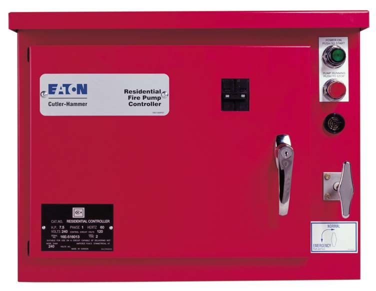
3.7 Pilot Devices
Controllers fitted with the RPT option are capable of
The green "POWER ON" light should be illuminated at fully automatic operation. Such controllers will start
all times when the circuit breaker is closed. If it is not automatically in response to the pressure switch and
then either there is no supply power to the controller or stop automatically when the pressure has been satisfied
the lamp is burned out. Corrective action should be and the RPT has timed out. Provision is made to convert
taken immediately. The green “POWER ON” light also automatic controllers to semi-automatic operation by
functions as the “START” pushbutton. The "START" disabling the effect of the RPT. This is done by means
pushbutton provides a manual start of the fire pump. of a jumper wire "b" between two points (3 & 3A) on
the terminal block as shown on the controller drawing.
When the pump is running, the red “PUMP RUNNING”
light should be illuminated. The red “PUMP For both automatic and semi-automatic operation, if the
RUNNING” light also functions as the “STOP” water pressure is NOT restored, the pump will stop
pushbutton. After a manual start, the "STOP" while the STOP pushbutton is held closed. Upon
pushbutton must be used to stop the fire pump. In all releasing the STOP pushbutton, the pump will restart.
fully automatic controllers, if the "START" pushbutton Note that the RPT will reset each time the STOP
is operated while the pump is already running because pushbutton is pressed.
of a pressure switch start, the manual stopping
provisions take over and the "STOP" pushbutton must Furthermore, if the controller is started manually, either
be used to stop the fire pump after pressure has been by the local/ remote start pushbutton or emergency
restored. handle, then it MUST be stopped manually by
depressing the STOP pushbutton.
3.8 Pressure Switch
4.2 Running Period Timer
The pressure switch (PS) is the normal means of starting
the fire pump in response to a lowering in water The running period timer (RPT) in conjunction with the
pressure in the fire protection system. The PS contact is pressure switch (PS) performs the automatic stopping
closed on low pressure and open on normal water function in a fire pump controller after a start initiated
pressure. by the pressure switch (PS). The RPT is set in the
factory for a delay of 3 minutes. If the pressure switch
3.9 Remote Start/Manual Start Relay (PS) responds to a loss of water pressure by closing its
contact, the main contactor (M) is energized. The
The remote start/manual start relay (1CR) is provided to contactor is maintained energized through a normally
facilitate the connection of a normally open remotely closed, timed open RPT contact for the preset time
located starting contact. Installation of this relay allows interval even if the PS contact re-opens in the interim.
the use of a remote starting contact rated at 120 volt, 60 At the end of the time interval, the RPT contact opens;
Hz with a making capacity of 70 VA and a continuous if the PS contact is open at that point, meaning system
capacity of 10 VA minimum. pressure has been restored, M is de-energized and the
pump stops. If the PS contact is still closed, M remains
energized and the pump continues to run until the PS
3.12 Low Suction (Option)
contact opens.
An additional pressure switch (LSPS) may be provided
The purpose of the running period timer is to ensure that
to signal low suction pressure by means of a white pilot
the pump motor is not subjected to frequent starts in
light on the controller enclosure.
response to a situation in which the pressure switch (PS)
contact repeatedly closes and opens at short time
intervals. RPT timing may be reduced for convenience
4. Operation of the Controller in testing the controller by turning the dial on the front
of the timer.
4.1 Semi-Automatic or Automatic Operation
Controllers with a pressure switch, but with the Running
Period Timer (RPT) disabled, are capable of semi-
automatic operation only. Such controllers will start
automatically in response to the pressure switch but
must be manually stopped with the “STOP” pushbutton.
Manual shutdown shall also be provided where required
by the authority having jurisdiction.
Effective February 2009IM05805006K Page 5
In addition, the provision of a sequential start timer on
4.3 Sequential Start Timer (Option) the lead pump, set to a few seconds delay, will prevent
the pump controller from responding to momentary
The sequential start timer (SST) delays the starting of hydraulic transient pressure loss which would otherwise
the fire pump in response to the closing of the PS start the fire pump unnecessarily. (This feature may be
contacts. In duplex systems (SST standard on lag considered as a "Time Delay Start" option.)
pump) it delays starting of the lag pump in addition to
any delay added to the lead pump start. It does not The sequential start timing device can provide a delay
delay a pushbutton or emergency handle start. This from 1-60 seconds. Adjustment is by means of a dial on
timing is accomplished by means of an electronic timing the front of the timer. The lead pump would normally
device. The timed contacts are used to delay starting the have its time delay set to minimum and the lag pump
motor for a preset time after the PS contacts close. would have its time delay set to 5 seconds. If hydraulic
This ensures that the starting inrush currents of all the transients are a problem, both timers can be adjusted for
pump motors are not simultaneously imposed on the a few seconds extra time delay.
power supply.
Effective February 2009Page 6 IM05805006K
FIGURE #1
Effective February 2009IM05805006K Page 7
FIGURE #2
Effective February 2009Eaton Corporation
10725 - 25th Street NE Unit 124
Calgary, Alberta, Canada
© 2009 Eaton Corporation T3N 0A4
All Rights Reserved Tel: +1-403-717-2000
Printed in Canada Fax: +1-403-717-0567
Publication No.: IM05805006K email: chcfirepump@eaton.com
February 2009 www.chfire.comYou can also read