Francis turbine dynamic stresses measurements at model and prototype scales
←
→
Page content transcription
If your browser does not render page correctly, please read the page content below

IOP Conference Series: Earth and Environmental Science

PAPER • OPEN ACCESS

Francis turbine dynamic stresses measurements at model and prototype
scales
To cite this article: Chamberland-Lauzon J. et al 2021 IOP Conf. Ser.: Earth Environ. Sci. 774 012081

View the article online for updates and enhancements.

 This content was downloaded from IP address 46.4.80.155 on 21/09/2021 at 23:32
30th IAHR Symposium on Hydraulic Machinery and Systems IOP Publishing
IOP Conf. Series: Earth and Environmental Science 774 (2021) 012081 doi:10.1088/1755-1315/774/1/012081

Francis turbine dynamic stresses measurements at model and
prototype scales

 Chamberland-Lauzon J., DiSciullo J., Monette C., Nennemann B., Afara S.
 Andritz Hydro Canada Inc., 6100 Transcanada Highway, Pointe-Claire, H9R 1B9

 Joel.Chamberland-Lauzon@andritz.com

 Abstract. A strain gauge and pressure measurement campaign on a model runner with a modern
 design was performed. The reference prototype runner was commissioned in 2013 and strain
 gauge measurements on the prototype are available for comparison. The model runner was
 fabricated by stereolithography in a plastic composite selected to obtain mechanical homology.
 The instrumented model runner was tested from 14% to 100% of the maximum guide vane
 opening at various speed factors (nED) by combining different head levels and rotating speeds as
 well as varying the cavitation coefficient (sigma) so that the effect of each studied parameter can
 be identified and quantified. By adjusting the speed and the head of the model test, it was also
 possible to induce rotor-stator resonance of the runner and to confirm expected hydrodynamic
 damping behaviour. Finally, the model scale pressure and stress measurements are compared to
 the ones obtained by both prototype measurements and CFD/FSI simulations.

1. Introduction
 Hydraulic turbines are now required to operate in extended operating ranges to fulfil market
demands. The challenge to design fixed blade turbines for extended range operation is now widely
discussed in the literature, most specifically the challenges in predicting the stochastic pressure loads
along with the induced dynamic stresses occurring in such operating conditions. The use of model scale
strain gauge measurements can be used to investigate the complex Fluid Structure Interaction (FSI)
phenomena [10,12]. The use of a test rig allows for performing tests at many speeds, heads and setting
conditions as well as performing flow visualization. Altogether, it is expected that such a measurement
campaign brings valuable insight into the understanding of hydraulic phenomena occurring on Francis
units operated at Part Load (PL), Deep Part Load (DPL) and Speed No Load (SNL).
 The model was instrumented with eight uniaxial strain gauges on two runner blades and two pressure
sensors in one runner blade channel. The model is fully homologous to the prototype runner which was
commissioned in 2013 and subject to a prototype strain gauge measurement campaign. The model test
was performed solely for scientific purposes as the prototype was found to be robust and suitable for
long term operation. This paper presents the results of the SNL, DPL and PL stress measurements of
both the model and the prototype runners. Rotor Stator Interaction (RSI) hydrodynamic damping is also
obtained. Finally, the results from model and prototype measurements are compared to simulation
results.

 Content from this work may be used under the terms of the Creative Commons Attribution 3.0 licence. Any further distribution
 of this work must maintain attribution to the author(s) and the title of the work, journal citation and DOI.
Published under licence by IOP Publishing Ltd 1
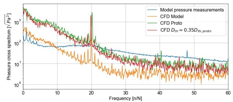
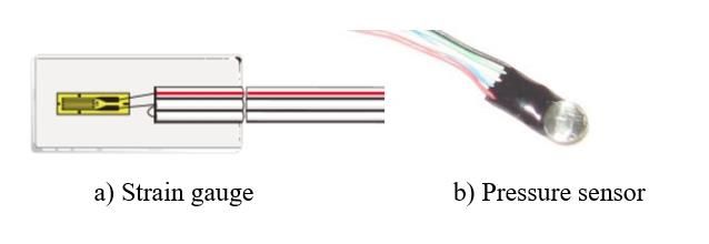
30th IAHR Symposium on Hydraulic Machinery and Systems IOP Publishing
IOP Conf. Series: Earth and Environmental Science 774 (2021) 012081 doi:10.1088/1755-1315/774/1/012081

2. Model instrumentation setup

2.1. Test rig
 The model test measurements were performed in 2018 at Andritz Hydro’s Lachine Laboratory in
Canada on test rig 4. The test rig has a 522kW pump capable of achieving a maximum head of 45m and
a maximum discharge of 1.38m3/s. A 373kW motor brake is used to create a dissipative torque for
turbines measuring 300 to 500 millimeters in reference diameter. A 37kW vacuum pump can produce
pressures down to 95kPa below absolute in order to recreate the desired sigma levels. The rig has both
a low (1Hz) and a high speed (up to 10kHz) data acquisition system to read data from all instrumentation.
For this project, a telemetry system attached to the rotating turbine shaft was employed to relay strain
and pressure information back to the high-speed data acquisition system.

2.2. Runner fabrication
 The runner was fabricated by stereolithography (3D printing) from a polymer composite. The blade
surfaces were polished, and the crown and band seal surfaces were machined. The geometry includes
fillets at junctions between blades and crown and band. The runner blades, crown and band are
mechanically homologous to the prototype runner in areas of interest.
 The material was selected so that the runner can be tested at resonance under RSI excitation. The
prototype frequency ratio between the potentially excited mode and the excitation frequency is also
replicated on the model. The properties of the plastic material were tested by 3 points flexion on
instrumented samples. The Young Modulus was tested parallel and transverse to the printing direction,
and values were found to be within 6% of each other.

2.3. Instrumentation
 Pressure measurements were performed using 2 watch battery style surface mount sensors
measuring 3mm in diameter and 1mm thickness. Entran model EPL-B03-7B sensors were used. They
were stainless-steel absolute pressure sensors with a 0 to 7bar range, 0 to 60°C temperature
compensation, and a special 4V excitation to go with our telemetry system.

 Figure 1 – Sensors used for model measurements

 Strain measurements were performed using 8 water proof 3 wire, quarter bridge strain gauges by
Kyowa (model KFWS-2N-120-C1-23 L1M3R). The sensors were connected to a specially made,
waterproof 32 pin connector in order to bring excitation to and signals from the sensors, to a telemetry
system made by KMT as shown in Figure 2. Signals from the telemetry system were sent wirelessly to
a Quantum X data acquisition module. All signals were sampled at a frequency of 2400Hz.

2.4. Test plan
 The test plan was designed to test the influence of many parameters on the Deep Part Load
behaviour of the runner; head (16m < Hm < 32m), rotating speed (700RPM ≤ N ≤ 900RPM) and sigma
(0.02 < σ < 0.12, σplant=0.095). For every speed, flow is varied at constant nED (0.29 < nED < 0.32,
nED,proto = 0.30) and constant sigma. The summary of the nED constant curves, various guide vane
openings at constant speed coefficients, performed for the deep part load investigation is presented in
Table 1.

 2
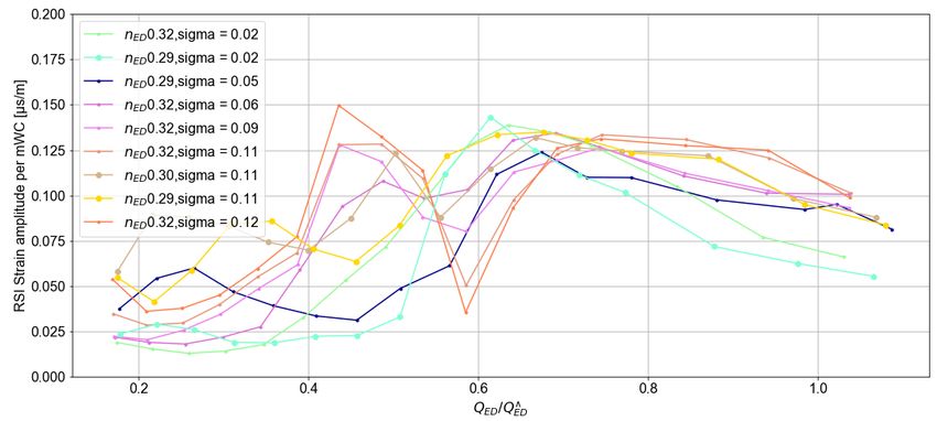
30th IAHR Symposium on Hydraulic Machinery and Systems IOP Publishing
IOP Conf. Series: Earth and Environmental Science 774 (2021) 012081 doi:10.1088/1755-1315/774/1/012081

 ^
 In the second phase of the test plan, a peak search at constant QED / = 1 with varied rotation
speed is performed to plot the transfer function of the runner to the Rotor Stator Interaction (RSI) for
the evaluation of the model runner natural frequency and damping.

 Figure 2 – Telemetry system for rotor instrumentation

Table 1 – Deep part load dynamic stress investigation test conditions

 Speed
 nED σ
 [RPM]
 0.320 0.091 0.110
 700 0.300 0.110
 0.292 0.091 0.110
 0.320 0.110
 800
 0.292 0.110
 0.320 0.020 0.056 0.091 0.110 0.121
 900 0.300 0.110
 0.292 0.020 0.056 0.110

3. Model measurement analysis
 The strain gauge and pressure signals are processed using in-house signal processing algorithms.
The average of the signals is removed using a detrend algorithm so that the calculated RMS values are
representative of the dynamic portion of the signal only.

3.1. Effect of Speed
 The results (RMS of dynamic portion of signal) from various nED constant curves with high and
 ^
comparable sigma (0.11 < σ < 0.12) are plotted along / values in Figure 3 for the strain gauge
with the higher stress amplitude. Reynolds number is as per convention of Hydraulic Laboratories and
depends only on the tangential velocity of the runner and the kinematic viscosity which varies slightly
with the water temperature during the tests.

 3
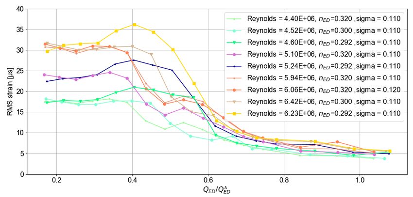
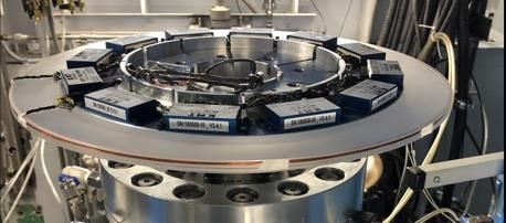
30th IAHR Symposium on Hydraulic Machinery and Systems IOP Publishing
IOP Conf. Series: Earth and Environmental Science 774 (2021) 012081 doi:10.1088/1755-1315/774/1/012081

 ^
 Figure 3 – RMS strains as function of / for various nED and Reynolds numbers

 For each nED constant curve, the tendency observed is very similar to the ones observed on many
 ^
prototypes [2,7], where the dynamic stresses are typically higher from SNL to / ≤ 0.4 and
 ^
decrease toward the high efficiency zone / ≥ 0.6.
 The different signals are grouped around similar Reynolds number values or rotating speeds
 ^
especially below / ≤ 0.2. Even if the model head varies significantly from nED=0.29 to
nED=0.32 for a given Reynolds number it does not significantly influence the dynamic stresses
measured close to speed-no-load. In summary, for a specific runner, the dynamic stresses near SNL
depend strongly on Reynolds number but are relatively independent of test head.

3.2. Effect of sigma
 The results at the highest Reynolds numbers (5.9E6 to 6.2E6) are used to compare the effect of
 ^
sigma. RMS values of a typical strain gauge are plotted against / values for various values of
σ (0.02 < σ < 0.12, σplant=0.095) and nED (0.29 < nED < 0.32, nED,proto = 0.30) in Figure 4.

 ^
 Figure 4 – RMS strains as function of / for various nED and Re > 5.9E6

 4
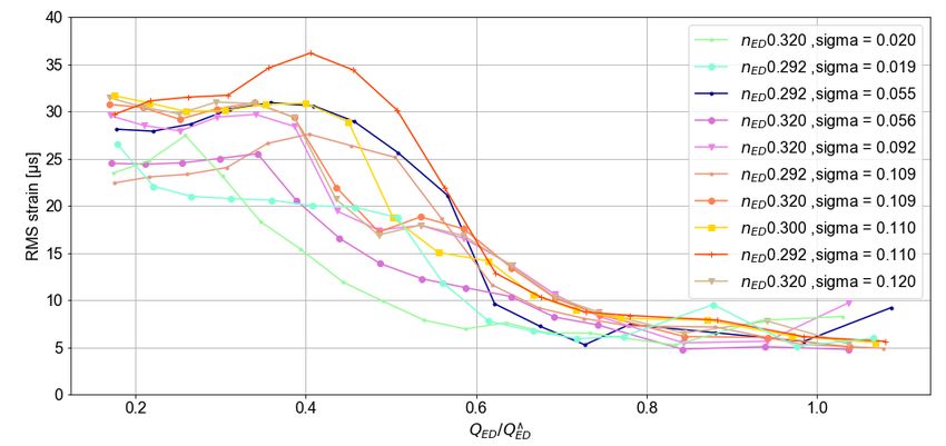
30th IAHR Symposium on Hydraulic Machinery and Systems IOP Publishing IOP Conf. Series: Earth and Environmental Science 774 (2021) 012081 doi:10.1088/1755-1315/774/1/012081 ^ For the DPL zone (0.3 0.6 where the RSI stresses decrease almost linearly with the increase of the flow. It is shown in other papers [2,5] that this variation is due to an increase of the hydrodynamic damping with the flow velocity. Figure 5 – Measured RSI strains per mWC at 900 RPM and for various σ values ^ In the region between 0.45 ≤ / ≤ 0.70, the observed behavior may highly vary from the one typically seen on prototype measurements. The nED and the values are driving the amount of vapor in the flow which is showing to have an importance for the lowest QED at which the RSI stresses show their full amplitude. Also, in some cases, an interaction between the rope and the RSI pressure can decrease the RSI stress amplitude in a significant way. In the second test, a peak search with variation of the rotation speed at constant guide vane opening and σ is performed to plot the transfer function of the runner strains. The RSI strain amplitudes per mWC as a function of the excitation frequency are presented in Figure 6 for five strain gauges where dots are the measured points and lines are the transfer function best fits. The fitted parameters are force 5
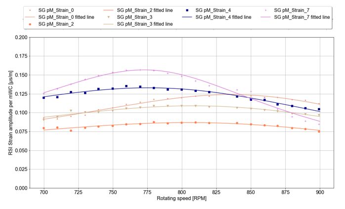
30th IAHR Symposium on Hydraulic Machinery and Systems IOP Publishing IOP Conf. Series: Earth and Environmental Science 774 (2021) 012081 doi:10.1088/1755-1315/774/1/012081 divided by the stiffness (F/K), the natural frequency (fn) and the damping (ζ). Strain gauges 1, 2 and 3 are on one blade while strain gauges 4 and 7 are on a second blade. Figure 6 – Transfer function parameter fitting (nED 0.30, QED = 0.21, σ = 0.109) The two blades exhibited different natural frequencies, with a 6% difference. One possible explanation may be due to geometrical variations due to the manufacturing process. The resulting natural frequencies and total damping values are presented in Table 2. The hydrodynamic damping is obtained by subtracting the plastic material damping from the obtained total damping. The plastic material damping was determined experimentally The uncertainty on the values is calculated for a 95% confidence interval. Table 2 – RSI fitted parameters Rotating frequency for Total damping Hydrodynamic resonance damping hyd [RPM] [%] [%] Blade 1 847 ± 11.8 17.8± 6.6 15.7± 6.9 Blade 2 792 ± 23.0 The damping ratio is defined as the ratio between the damping coefficient and √ . As the damping (C) is induced by hydrodynamic forces it will not change with a different material. Therefore, the damping ratio for a steel runner at the same scale can be calculated from the following equation with constant relative error. As per modal analysis, 20% of the modal mass is attributed to the structure. It is assumed that the mode shape is not affected by the runner material change. This damping value can be extrapolated to the prototype scale by scaling with the flow velocity. [9] ζ ℎ , , ζ ℎ , , = = 3.53% √ ( − 0.2( − )) 6
30th IAHR Symposium on Hydraulic Machinery and Systems IOP Publishing
IOP Conf. Series: Earth and Environmental Science 774 (2021) 012081 doi:10.1088/1755-1315/774/1/012081

4. Prototype measurements

4.1. Prototype test conditions
 The prototype stress measurements were performed shortly after the commissioning of the units
with the intent of confirming the robustness of the runners predicted at the design stage. They were
performed at the conditions presented in Table 3. The tested conditions, except for the Reynolds
number, are within the value ranges tested on the model.

Table 3 – Prototype test conditions

 Parameter Prototype test values
 nED 0.30
 σ 0.110
 QED 0.02 to 0.24
 Reynolds number 2.46E8

4.2. Prototype instrumentation
 The prototype was instrumented with 10 strain gauges on two blades (5 locations per blades), see
Figure 7 for illustration. The strain gauge position and orientation was determined using FEM analysis
to enable reliable extrapolation to the peak stress locations.

 Figure 7 – Prototype measurements instrumentation

 The rotor instrumentation acquisition system is connected through WIFI to the main acquisition
system in a master/slave configuration allowing synchronized measurements between the rotor and the
stator.

4.3. Stress measurement results
 The measured stresses are presented in Figure 8. The stresses are normalized with the maximum
measured dynamic stress. In the graph, results from the model strain gauge tests from the same nED
and σ, are also added for reference. The results from both tests are normalized independently. The
extrapolation of the results from the model to the prototype scale is discussed in the next section.
 The tendency observed from both datasets are very similar. Dynamic stresses at the crown tend to
 ^
have a higher increase from / = 0.2 to 0.4 than at the band, which is seen on both the model
and the prototype. The sudden transition from the high stress zone to lower dynamic stresses occurs in
 ^
both cases at very similar QED values, which happens to be at slightly lower / than the rope.
An important conclusion from our data is that the modal and prototype stress distributions as a
function of flow are very similar.

 7
30th IAHR Symposium on Hydraulic Machinery and Systems IOP Publishing
IOP Conf. Series: Earth and Environmental Science 774 (2021) 012081 doi:10.1088/1755-1315/774/1/012081

 Figure 8 – Measured prototype and model runner dynamic stress

5. Comparison of measurements with simulations
 With the purpose of using the results from strain gauge measurements on a model for the
design of new prototypes, an investigation on the scalability of the pressure dynamic loads is performed.
CFD and FSI calculations are performed at model, prototype and at an intermediate scale (Dth = 35% of
prototype) so that results at more than two scales are available.

5.1. Pressure Spectra comparison
 The CFD and FSI methods are discussed in more detail in the literature [3,4,8,11]. The cross
spectra from the simulated results and measurements are calculated using the pressure signals from
both pressure sensors located in the runner channels. The spectra are shown in Figure 9. The positions
of the sensors are homologous for all scales.

 Figure 9 – Measured and simulated pressure cross spectra at various scales

 8
30th IAHR Symposium on Hydraulic Machinery and Systems IOP Publishing
IOP Conf. Series: Earth and Environmental Science 774 (2021) 012081 doi:10.1088/1755-1315/774/1/012081

 The comparison of the spectra obtained by simulation and the ones from the measurements exhibit
different behaviour for the relative frequency f/n > 10 where the CFD simulation does not have enough
spatial and temporal resolution to resolve the turbulence scales. Andritz’ internal FSI method solves this
lack of resolution for the prediction of the runner stresses [3,11].
 As discussed in previous publications [4,11], the CFD-FSI calculation for stochastic loads tends to be
overly-conservative for smaller machines with low stresses but accurate for larger machines. The FSI
analysis performed at the prototype scale of the machine investigated here shows good agreement with
the strain gauge measurements in Figure 10.

5.2. Extrapolation from model to prototype scale
 Scalability of turbulent pressure fluctuations is widely studied. Most of the publications focus on
thin foils, pipes or pipe bundles for either the aviation or nuclear industries. For some cases, it was
shown that the wall pressure fluctuations could be extrapolated using the natural logarithm of the
Reynolds number. The logarithmic regression between the Reynolds number and the normalized stress
is presented in Figure 10. This exercise assumes that the stress fluctuations are proportional to the wall
pressure fluctuations.

 Figure 10 – Extrapolation from model to prototype measurements: logarithmic regression with
 Reynolds number

 The regression from all the points (in yellow), including all scales, measurements and simulations,
has good quality with R2 > 0.95. However, the regression considering only model test points has a
quite different slope. Then if model test results are used to extrapolate stresses from the model scale to
the prototype scale an underprediction of about 40% is obtained, which indeed is not acceptable for
stress prediction and fatigue analysis of the prototype.
 Other extrapolation methods were investigated. While some are promising, classical parameters
such as the tangential speed and the head did not lead to satisfactory results. Extrapolation between
scales for similar hydraulic conditions is possible, however extrapolation to other conditions or other
turbine designs may not be possible without the contribution of CFD due to the complexity of the
flow.

6. Conclusion
 Strain gauge measurement campaigns on a mechanically homologous Francis turbine at model and
prototype scales were performed. The model was tested at 3 different Reynolds numbers, with variations
of nED, QED and σ. The exact conditions of the prototype test, except for Reynolds number, were
replicated at the model.
 From the results of the model strain gauge measurements it can be concluded that the SNL and DPL
stresses strongly depend on the Reynolds number, or the rotating speed. As expected, higher stresses are

 9
30th IAHR Symposium on Hydraulic Machinery and Systems IOP Publishing
IOP Conf. Series: Earth and Environmental Science 774 (2021) 012081 doi:10.1088/1755-1315/774/1/012081

found at higher Reynolds numbers. The σ value also influences the strain level especially in the inter-
blade vortex zone. It must be noted that the σ values at which lower dynamic stresses were found are
not typical of real prototype machines.
 The strain measurements from the model test show similar tendencies as the prototype strain
measurements when observed on an nED constant curve. However, the absolute scalability of model to
prototype strains are still under investigation.
 Measurement on a mechanically homologous model runner allows for the testing of many conditions
which are not possible to test on the prototype. Such measurement campaigns can provide valuable
information, not only specific to a design, but also for the scientific aspects pertaining to the design of
runners for 0-100% operation. Similar measurement campaigns combined with cutting edge flow
visualization techniques should provide highly valuable data for the study of these FSI phenomena.

References

[1] Coutu A., Marier S., Chamberland-Lauzon J., Monette C., “Designing Francis runners for 0-100
 per cent operation”, Hydro 2015, Bordeaux, France, October 2015
[2] Monette C., Marmont H., Chamberland-Lauzon J., Skagerstrand A., Coutu A., Carlevi J., “Cost
 of enlarged operating zone for an existing Francis runner”, IAHR 28th Symposium on Hydraulic
 Machinery and Systems, Grenoble, France, July 2016
[3] Nennemann B., Morissette J.-F., Chamberland-Lauzon J., Monette C., Braun O., Melot M., Coutu
 A., Nicolle J., Giroux A.-M., “Challenges in Dynamic Pressure and Stress Predictions at No-
 Load Operation in Hydraulic Turbines”, IAHR 27th Symposium on Hydraulic Machinery and
 Systems, Montreal, Canada, September 2014.
[4] Morissette J.F., Chamberland-Lauzon J., Nennemann B., Monette C., Giroux A.-M., Coutu A.,
 “Stress predictions in a Francis turbine at no load operating regime”, IAHR 28th Symposium
 on Hydraulic Machinery and Systems, Grenoble, France, July 2016
[5] Coutu A., Monette C., Velagandula O., “Francis Runner Dynamic Stress Calculations’’, Hydro
 2007, Granada, Spain, October 15-17, 2007
[6] Coutu A., Chamberland-Lauzon J., “The impact of flexible operation on Francis runners”, The
 International Journal on Hydropower & Dams, Volume Twenty Two, Issue 2, 2015.
[7] Coutu A., Gagnon M., Monette C. 2007, “Life Assessment of Francis Runners Using Strain Gage
 Site Measurements”, Waterpower XV, Chattanooga, TN
[8] Melot M., Monette C., Coutu A., Nennemann B., “A new Francis runner design procedure to
 predict static stresses at speed-no-load operation”, The International Journal on Hydropower
 & Dams, Volume Twenty One, Issue 1, 2014
[9] Nennemann B., Monette C., Chamberland-Lauzon J., “Hydrodynamic damping and stiffness
 prediction in Francis turbine runners using CFD”, IAHR 28th Symposium on Hydraulic
 Machinery and Systems, Grenoble, France, July 2016
[10] Avellan F. et al.., “HYdropower stations PERformance and flexiBle Operation towards Lean
 inte‐gration of new renewable Energies”, Final Report, FP7‐ENERGY‐2013‐1 – N° 608532 –
 HYPERBOLE
[11] Chamberland-Lauzon J., Monette C., Nennemann B., Melot M., Birk S., Ruchonnet N., “Francis
 design and prediction technology for flexible operation”, IAHR 29th Symposium on Hydraulic
 Machinery and Systems, Kyoto, Japan, September 2018.

 10
You can also read