Force Calibration Guidance for Beginners - Morehouse ...
←
→
Page content transcription
If your browser does not render page correctly, please read the page content below
Force Calibration Guidance for
Beginners

                  Force Calibration Guidance for Beginners
          Author: Henry Zumbrun, Morehouse Instrument Company
02/2022                                                         Page 1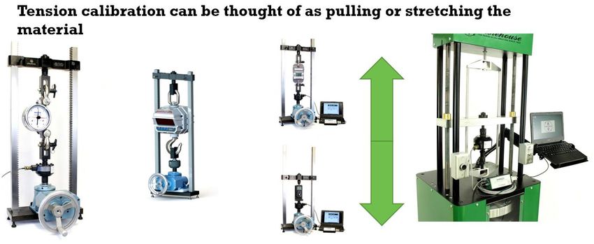
Table of Contents

Introduction ......................................................................................................................................................3
1.       Force Calibration and its Importance ......................................................................................................4
2.       How a Transducer Measures Force .........................................................................................................6
3.       Compression and Tension Force Calibration ..........................................................................................8
4.       Calibration versus Verification ..............................................................................................................10
5.       Measurement Uncertainty ....................................................................................................................13
6.       Load Cell Terminology ...........................................................................................................................15
7.       Types of Load Cells ................................................................................................................................22
8.       Load Cell Troubleshooting.....................................................................................................................28
9.       Indicator Basics .....................................................................................................................................33
10.      Force Calibration System Accuracy .......................................................................................................39
11.      Glossary of Terms ..................................................................................................................................45
12.      Additional Information ..........................................................................................................................49
13.      References.............................................................................................................................................50

                                                Force Calibration Guidance for Beginners
                                        Author: Henry Zumbrun, Morehouse Instrument Company
     02/2022                                                                                                                                              Page 2
Introduction
Morehouse Instrument Company has shared a tremendous amount of knowledge throughout the years
with blogs, technical papers, and webinars. This education aligns with our purpose, to create a safer world
by helping companies improve their force and torque measurements.

When someone is new to calibration or metrology, the information can be overwhelming. There is so much
to digest that people can quickly become overwhelmed. Some have joked that an introduction into
metrology is like trying to drink through a firehouse.

To simplify things, Morehouse has created this guidance document to help anyone new to force. Even
seasoned metrologists or technicians with years of experience may learn something new, or maybe this
document can act as a refresher for those who are more advanced. In either case, the knowledge gained
will ultimately help you become better.

                                       Figure 1: Force Calibration Basics

                                    Force Calibration Guidance for Beginners
                            Author: Henry Zumbrun, Morehouse Instrument Company
   02/2022                                                                                             Page 3
1. Force Calibration and its Importance
What is Force Calibration?
In his second law, Sir Isaac Newton stated that force controls motion; therefore, we must control the force
if we are to control the motion. An example of force: I have an egg in my hand and want to break it by
squeezing it in my hand. This egg will break at X known force. No matter where I am in the world, the same
amount of force will be required to break the egg in my hand. It will not take less force to break this egg in
Pennsylvania than in Peru.

A simple physics definition for force is mass times acceleration (F = m x a). As shown in the illustration
below, force is a derived unit from the SI base units of Mass, Time, and Length. The International
Committee for Weights and Measures in the Bureau International des Poids et Mesures (CIPM/BIPM)
defines 1N as the force required to accelerate 1 kg to 1 meter per second per second in a vacuum.

                                       Figure 2: SI Units courtesy of NIST 1

Calibration is the comparison of an unknown (typically referred to as the Unit Under Test or UUT) to a
device known within a certain error (typically referred to as the Calibration Standard or Reference Standard)
                                     Force Calibration Guidance for Beginners
                             Author: Henry Zumbrun, Morehouse Instrument Company
   02/2022                                                                                                   Page 4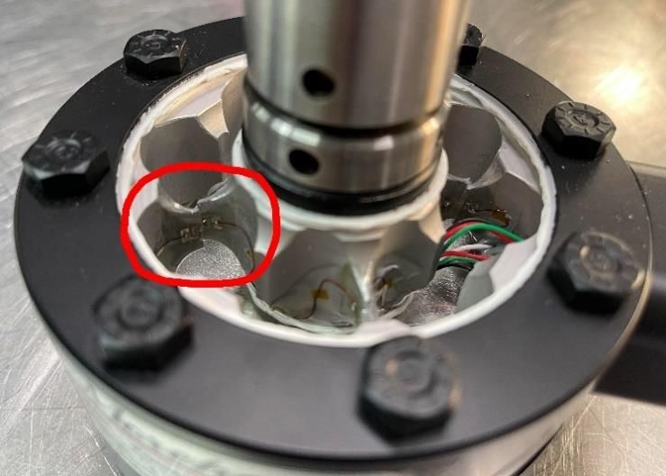
to characterize the unknown. Therefore, force calibration compares a force instrument to a force reference
standard to characterize the instrument.
Why is force measurement important?
The most straightforward answer is that bridges and other objects do not collapse when forces are exerted
upon them. When building a bridge, it is essential to get the concrete strength measurement correct. It is
essential to make sure the steel is tested, and the cables are appropriately checked for prestress or post-
tension. When these measurements are not done correctly, bad things happen, as shown below.

                                            Figure 3: Bridge Failure
In the example below, the ripeness of apples is being checked. Why may that be important? If you are in
California and want to distribute apples across the country, the harder ones will last longer and ripen during
shipment. In contrast, the softer ones might be distributed locally.

                                        Figure 4: Testing Apple Ripeness
The example below shows the fishing line being tested. I am sure any fisherman would not want the line to
break as they haul in their prized fish.

                                    Force Calibration Guidance for Beginners
                            Author: Henry Zumbrun, Morehouse Instrument Company
   02/2022                                                                                              Page 5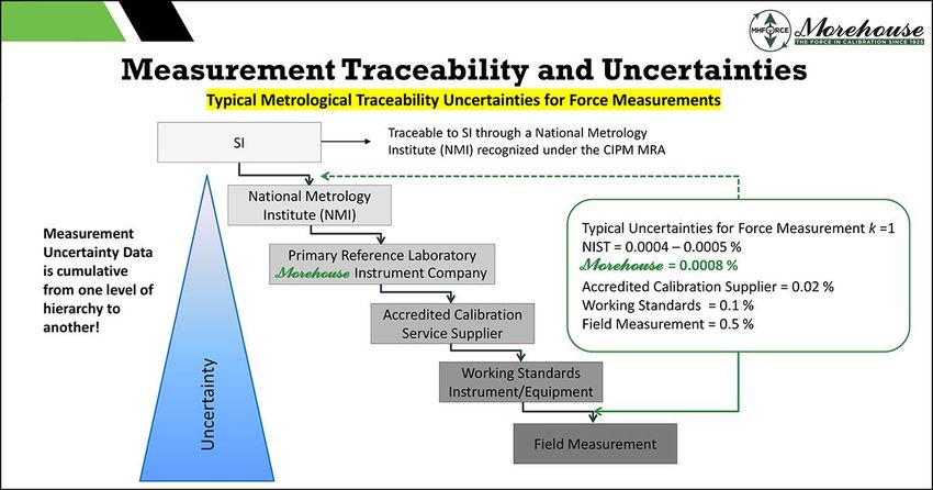
Figure 5: Testing Fishing Line
In general, the measurement of force is performed so frequently that we tend to take it for granted.
However, almost every material item is tested using some form of traceable force measurement. Testing
may vary from sample testing on manufactured lots and might include anything from the materials used to
build your house to the cardboard on that toilet paper roll.

2. How a Transducer Measures Force

What is a Transducer?
In the broad sense of the term, a transducer is a device that turns one type of energy into another type.
Some examples are:

                                       Figure 6: A Battery is a Transducer

    1. A battery is a transducer that converts chemical energy into electrical energy. The chemical
       reactions involve electrons' flow from one material to another through an external circuit.

                                    Force Calibration Guidance for Beginners
                            Author: Henry Zumbrun, Morehouse Instrument Company
   02/2022                                                                                             Page 6
Figure 7: A Thermometer is Transducer
    2. A thermometer is a transducer that converts heat energy into the mechanical displacement of a
       liquid column. As the temperature around the bulb heats up, the liquid expands and rises.

                                       Figure 8: A Load Cell is a Transducer

    3. A load cell is a transducer that converts mechanical energy into electrical signals. As compressive or
       tensile force is exerted on a load cell, the mechanical energy is converted into equivalent electrical
       signals.

How a load cell measures compression and tension force

As force is exerted on a load cell, the material deflects. The deflection is typically measured by a strain
gauge, which is placed on the material inside the load cell.

                                     Force Calibration Guidance for Beginners
                             Author: Henry Zumbrun, Morehouse Instrument Company
   02/2022                                                                                                    Page 7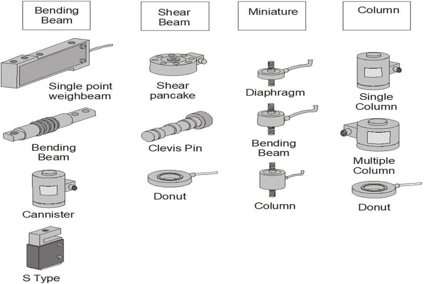
Figure 9: Strain Gauge

When placed appropriately, the strain gauge will measure the change in resistance as force is applied. The
ideal load cell only measures force in defined directions and ignores force components in all other
directions. Approaching the ideal involves optimizing many design choices, including the mechanical
structure, the gage pattern, placement on the gages, and the number of gages.

When a meter or indicator is hooked up to a load cell, it displays the force measurement value. A load cell
may be calibrated at a company like Morehouse using deadweight primary standards known to within 0.002
% of applied force. The machine's deadweights are adjusted for local gravity, air density, and material
density to apply the force accurately. The weights are used to calibrate the load cell, which may be used to
calibrate and verify a testing machine.

3. Compression and Tension Force Calibration
This section covers the terms compression and tension and how they relate to force calibration.

What is a Compression Calibration?
When discussing compression calibration, we should think about something being compressed or
something being squeezed. I like to describe compression calibration as pushing or squeezing something.

                                   Force Calibration Guidance for Beginners
                           Author: Henry Zumbrun, Morehouse Instrument Company
   02/2022                                                                                            Page 8
Figure 10: Compression Calibration Examples
Above are two examples of a compression setup in a calibrating machine. The machine on the left is
compressing both load cells by creating an upward force. The picture on the right is a compression setup in
the deadweight machine where a downward force compresses the load cell.
The key to this type of calibration is making sure everything is aligned and that the line of force is as straight
as possible. I like to say free from eccentric or side forces. The key to proper alignment is using the right
adapters in the calibrating machine, from alignment plugs to top adapters.
Morehouse has a technical paper on recommended compression and tension adapters for force
calibration that can be found on our website.
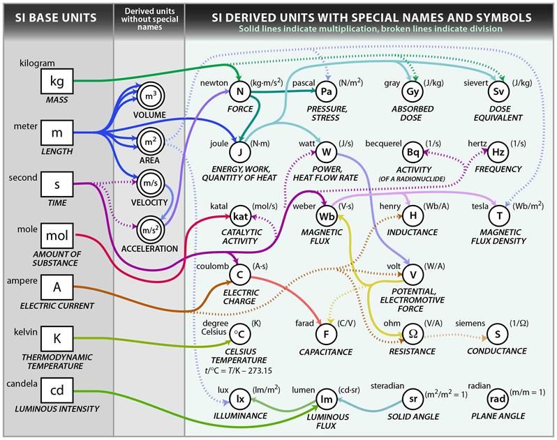
What is a Tension Calibration?
When discussing tension calibration, we should think of something being stretched. I like to describe
tension calibration as a pull.
Force Calibration Guidance for Beginners
Author: Henry Zumbrun, Morehouse Instrument Company
02/2022 Page 9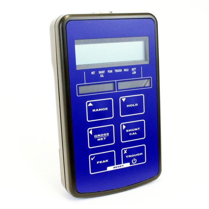
Figure 11: Tension Calibration Examples

Above are multiple examples of tension setups in calibrating machines. The machine on the left is the
Morehouse benchtop calibrating machine. A dynamometer is fixed to a stationary beam, and force is
generated by pulling on the load cell and the dynamometer. More examples are shown with different
instruments, from crane scales to hand-held force gauges. The picture on the right shows a load cell fixtured
for tension calibration in a Morehouse deadweight machine. The load cell is fixtured to the frame, and the
weights are applied and hung, which stretches the material. The key to getting great results in tension
calibration is also adapters.

The ISO 376 Annex gives excellent guidance on adapters that help keep the line of force pure. It states,
”Loading fittings should be designed in such a way that the line of force application is not distorted. As a
rule, tensile force transducers should be fitted with two ball nuts, two ball cups, and, if necessary, with two
intermediate rings, while compressive force transducers should be fitted with one or two compression
pads.”2 Morehouse follows the ISO 376 standard for several of our products. We also design adapters to
help technicians and end-users to replicate and reproduce calibration results.

4. Calibration versus Verification
Calibration and verification are not the same. This section describes the differences between calibration and
verification.

What is a Calibration?

Let me start by stating that there are several definitions of calibration across multiple standards. My
favorite definitions are below:

Calibration is the comparison of an unknown (typically referred to as the Unit Under Test or UUT) to a
                                    Force Calibration Guidance for Beginners
                            Author: Henry Zumbrun, Morehouse Instrument Company
   02/2022                                                                                                Page 10
device known within a certain error (typically referred to as the Calibration Standard or Reference Standard)
to characterize the unknown. Thus, we are comparing something that we know to some degree of certainty
to something that may not be known or that needs to be checked at a time interval to assure drift and other
characteristics are kept under control. Thus, in simple terms, calibration can be thought of as validation.
Figure 12: Calibration Definition
The definition from the International Vocabulary of Metrology (VIM) in section 2.39 is interesting in that
many people assume calibration is also an adjustment. It is not. The VIM is clear in Note 2, stating,
"Calibration should not be confused with a measuring system, often mistakenly called "self-calibration," nor
with verification of calibration." Think about it this way; when you send most instruments to a National
Metrology Institute such as NIST, they will only report the value of the device at specific points and the
associated measurement uncertainties. Why? Because the end-user can take those values and use those
values with the associated measurement uncertainties as a starting point to characterize whatever is being
tested. Measurement uncertainty will be explained in the next section.
When an end-user uses a calibrated device, it is often under different conditions than when it was
calibrated. For example, if Morehouse calibrates a device in one of our deadweight machines known to
better than 0.002 % of applied force, and the end-user later uses this device, then the conditions will vary. It
is almost certain that their use conditions do not replicate those exactly of the lab performing the
calibration. For example, the temperature, rigidity of the machine, and hardness of adapters could vary, and
their machine could introduce torsion, etc. These are only a few of several conditions that can impact the
results.
I like to explain that Morehouse calibrates the device and assigns a value that can be considered the
Force Calibration Guidance for Beginners
Author: Henry Zumbrun, Morehouse Instrument Company
02/2022 Page 11expected performance of the device under the same conditions at which it was calibrated. The end-user
then varies those conditions, which adds additional measurement uncertainty. Therefore, the end-user can
use the calibration data as a starting point to evaluate their measurement uncertainty.
What is Verification?
The VIM in section 2.44 defines verification as the provision of objective evidence that a given item fulfills
specified requirements. Then the VIM goes on to list several additional examples:
• Example 1: Confirmation that a given reference material as claimed is homogeneous for the
quantity value and measurement procedure concerned, down to a measurement portion having a
mass of 10 mg.
• Example 2: Confirmation that performance properties or legal requirements of a measuring system
are achieved.
• Example 3: Confirmation that a target measurement uncertainty can be met.
Note 1: When applicable, measurement uncertainty should be taken into consideration.
Note 2: The item may be, e.g., a process, measurement procedure, material, compound, or measuring
system.
Note 3: The specified requirements may be, e.g., that a manufacturer's specifications are met.
Note 4: Verification in legal metrology, as defined in VIML [53], and in conformity assessment in general,
pertains to the examination and marking and/or issuing of a verification certificate for a measuring system.
Note 5: Verification should not be confused with calibration. Not every verification is a validation.
Note 6: In chemistry, verification of the identity of the entity involved, or of activity, requires a description
of the structure or properties of that entity or activity.
For example, a 10,000-load cell, like the one shown below, is submitted to Morehouse, and found to be
within ± 5 lbf, as per the customer's required tolerance of 0.05 % of full scale.
Force Calibration Guidance for Beginners
Author: Henry Zumbrun, Morehouse Instrument Company
02/2022 Page 12Figure 13: Morehouse Ultra-Precision Load Cell
In this scenario, verification is more of a conformity assessment and should not be confused with
calibration. However, many commercial laboratories perform a calibration by reporting the applied force
and the device's corresponding measurement values for calibration. Then they make a conformity
assessment, which is a statement to the end-user that the device is either in or out of tolerance. They
typically say a device passes calibration or it fails calibration.
The critical detail here is that to ensure measurement traceability, measurement uncertainties must be
reported. You should not perform a calibration with a statement of verification without reporting the
measurement uncertainty. That uncertainty should be considered when making a statement of
conformance to a specification.
Therefore, these definitions and examples show how calibration and verification are not the same.
5. Measurement Uncertainty
What is Measurement Uncertainty?
What measurement uncertainty is not is an error. It is imperative to understand the difference between
these two terms as they are often confused. Error is the difference between the measured value and the
device's actual value or artifact being measurement. In many cases, we try to correct the known errors by
applying corrections sometimes from the calibration certificate. These corrections can be a curve, a
diagram, a table, all items found in note 1 of the calibration definition from the VIM.
Uncertainty, often referred to as 'doubt,' is the quantification of 'doubt' about the measurement result. The
Force Calibration Guidance for Beginners
Author: Henry Zumbrun, Morehouse Instrument Company
02/2022 Page 13VIM in section 2.26 defines uncertainty as a non-negative parameter characterizing the dispersion of the
quantity values being attributed to a measurand, based on the information used. The VIM goes into further
detail with several notes about the included components of measurement uncertainty, such as those arising
from systematic effect, components associated with corrections, assigned quantity values of measurement
standards, etc. Measurement Uncertainty compromises many components.
OIML G 19:2017 sums the definition of uncertainty as "the concept of measurement uncertainty can be
described as a measure of how well the 'true' value of the measurand is believed to be known."
One of the best guides to Uncertainty is JCGM 100:2008 Evaluation of measurement data — Guide to the
expression of uncertainty in measurement free to download at
https://www.bipm.org/en/publications/guides/gum.html.
In general, when you calculate measurement uncertainties following ISO "Guide to the Expression of
Uncertainty in Measurement" (GUM) and ILAC (International Laboratory Accreditation Cooperation) P-14 as
required by ISO/IEC 17025 guidelines, you will need to consider the following:
• Repeatability (Type A)
• Resolution
• Reproducibility
• Reference Standard Uncertainty
• Reference Standard Stability
• Environmental Factors
Morehouse has written several published documents on the topic of measurement uncertainty. We
have created a spreadsheet tool to help everyone correctly calculate uncertainty for force following
accreditation requirements and in line with JCGM 100:2008. That tool can be found at
https://measurementuncertainty.info/
Why is Measurement Uncertainty Important?
The uncertainty of the measurement is required to be reported on a certificate of calibrations if you are
accredited to ISO/IEC 17025:2017, as well as several other standards. It is essential if your customer may
want you to make a statement of conformance on whether the device or artifact is in tolerance or not. It
may need to be considered if you do a test and want to know if the device passes or fails. Measurement
Uncertainty is required to establish your measurement traceability, which is defined in the Vim as property
of a measurement result whereby the result can be related to a reference through a documented unbroken
chain of calibrations contributing to the measurement uncertainty.
Force Calibration Guidance for Beginners
Author: Henry Zumbrun, Morehouse Instrument Company
02/2022 Page 14Figure 14: An Example of Measurement Traceability for Force
In simplistic terms, the measurement uncertainty is crucial because you want to know that the laboratory
performing the calibration of your device or artifact can perform the calibration. If you need a device to be
known to within less than 0.02 %, you must use a calibration provider that gives you the best chance of
achieving that result. If the calibration provider has a stated measurement uncertainty of 0.04 %,
mathematically, they are not the right calibration lab to calibrate or verify your device or artifact.
Measurement uncertainty also keeps us honest. If a laboratory claims traceability to SI through NIST, the
larger the uncertainty becomes, the further away from NIST. The above picture shows this concept as the
further away from SI units, the more significant the uncertainty.
Your Measurement Uncertainty is directly affected by the standards used to perform the calibration.
Morehouse offers the lowest uncertainties for a commercial calibration laboratory. We work with
customers to help lower their measurement risk. We have been successful in helping our customers make
better measurements for over a century.
6. Load Cell Terminology
Non-Linearity, Non-Repeatability, Hysteresis, and Static Error Band are common load cell terminology
typically found on a load cell specification sheet. There are several more terms regarding the characteristics
and performance of load cells. However, I chose these four because they are the most common
specifications found on certificates of calibration.
Force Calibration Guidance for Beginners
Author: Henry Zumbrun, Morehouse Instrument Company
02/2022 Page 15When broken out individually, these terms can help you select the suitable load cell for an application.
Some of these terms may not be as important today as they were years ago because better meters are
available that overcome inadequate specifications. One example is Non-Linearity. An indicator capable of
multiple span points can significantly reduce the impact of a load cell's non-linear behavior.
The meanings for these terms are described in detail below.
Figure 15: Morehouse Load Cell Specification Sheet
Non-Linearity: The quality of a function that expresses a relationship that is not one of direct proportion.
For force measurements, Non-Linearity is defined as the algebraic difference between the output at a
specific load and the corresponding point on the straight line drawn between the outputs at minimum load
and maximum load. It usually is expressed in units of % of full scale. It is usually calculated between 40 - 60
% of the full scale.
Force Calibration Guidance for Beginners
Author: Henry Zumbrun, Morehouse Instrument Company
02/2022 Page 16Figure 16: Non-Linearity Expressed Graphically
Non-Linearity is one of the specifications that would be particularly important if the indicating device or
meter used with the load cell only has a two-point span, such as capturing values at zero and capacity or
close to capacity. The specification gives the end-user an idea of the anticipated error or deviation from the
best fit straight line. However, suppose the end-user has an indicator capable of multiple span points and
uses coefficients from an ISO 376 or ASTM E74 type calibration. In that case, the non-linear behavior can be
corrected, and the error significantly reduced.
One way to calculate Non-Linearity is to use the slope formula or manually perform the calibration by using
the load cell output at full scale minus zero and dividing it by force applied at full scale and 0. For example, a
load cell reads 0 at 0 and 2.00010 mV/V at 1000 lbf. The formula would be (2.00010-0)/ (1000-0) = 0.002.
This formula gives you the slope of the line assuming a straight line relationship. There are some
manufactures who take a less conservative approach and use higher order quadratic equations.
Plot the Non-Linearity baseline as shown below using the formula of force applied * slope + Intercept or y =
mx +b. If we look at the 50 lbf point, this becomes 50 * 0.0020001 +0 = 0.100005. Thus at 50 lbf, the Non-
Linearity baseline is 0.100005.
To find the Non-Linearity percentage, take the mV/V value at 50 lbf minus the calculated value and divide
by the full-scale output multiplied by 100 to convert to a percentage. Thus, the numbers become ((0.10008-
0.100005)/2.00010) *100) = 0.004 %.
Force Calibration Guidance for Beginners
Author: Henry Zumbrun, Morehouse Instrument Company
02/2022 Page 17Non-Linearity Calculations Ignoring Ending Zero though Running it through the formula
Non-
Force Appied Linearity Non-Linearity
(lbf) Run 1 Adjusted Base line (%FS) Non-linearity Line
0 0.00000 0 0.000 Slope= 0.0020001
50 0.10008 0.1000050 0.004 Intercept= 0
100 0.20001 0.2000100 0.000
200 0.40002 0.4000200 0.000
300 0.60001 0.6000300 0.001 Non-linearity= 0.004
400 0.80002 0.8000400 0.001 (%FS)
500 1.00005 1.0000500 0.000
600 1.20002 1.2000600 0.002
700 1.40003 1.4000700 0.002
800 1.60004 1.6000800 0.002
900 1.80006 1.8000900 0.001
1000 2.00010 2.0001000 0.000
0 0.00000 0
Figure 17: Non-Linearity Baseline
Non-Linearity Calculations Reducing Ending Zero
Force Appied (lbf) Run 1 Adjusted Non-Linearity Base line Non-Linearity (%FS) Non-linearity Line
0 =(E7*$K$7+$K$8) =ROUND(ABS(F7-G7)/$F$18*100,3) Slope= =(F18-F7)/(E18-E7)
50 0.10008 =(E8*$K$7+$K$8) =ROUND(ABS(F8-G8)/$F$18*100,3) Intercept= 0
100 0.20001 =(E9*$K$7+$K$8) =ROUND(ABS(F9-G9)/$F$18*100,3)
200 0.40002 =(E10*$K$7+$K$8) =ROUND(ABS(F10-G10)/$F$18*100,3)
300 0.60001 =(E11*$K$7+$K$8) =ROUND(ABS(F11-G11)/$F$18*100,3) Non-linearity=
400 0.800015 =(E12*$K$7+$K$8) =ROUND(ABS(F12-G12)/$F$18*100,3) (%FS) =MAX(H7:H19)
500 1.00005 =(E13*$K$7+$K$8) =ROUND(ABS(F13-G13)/$F$18*100,3)
600 1.200015 =(E14*$K$7+$K$8) =ROUND(ABS(F14-G14)/$F$18*100,3)
700 1.400025 =(E15*$K$7+$K$8) =ROUND(ABS(F15-G15)/$F$18*100,3)
800 1.60004 =(E16*$K$7+$K$8) =ROUND(ABS(F16-G16)/$F$18*100,3)
900 1.80006 =(E17*$K$7+$K$8) =ROUND(ABS(F17-G17)/$F$18*100,3)
1000 2.0001 =(E18*$K$7+$K$8) =ROUND(ABS(F18-G18)/$F$18*100,3)
0 =(E19*$K$7+$K$8)
Figure 18: Non-Linearity Calculations
Hysteresis: The phenomenon in which the value of a physical property lags changes in the effect causing it.
An example is when magnetic induction lags the magnetizing force. For force measurements, Hysteresis is
often defined as the algebraic difference between output at a given load descending from the maximum
load and output at the same load ascending from the minimum load.
Force Calibration Guidance for Beginners
Author: Henry Zumbrun, Morehouse Instrument Company
02/2022 Page 18Figure 19: Hysteresis Example
Hysteresis is normally expressed in units of % full scale. It is normally calculated between 40 - 60 % of full
scale. The graph above shows a typical Hysteresis curve where the descending measurements have a
slightly higher output than the ascending curve.
If the end-user uses the load cell to make descending measurements, then they may want to consider the
effect of Hysteresis.
Errors from hysteresis can be high enough that if a load cell is used to make descending measurements,
then it must be calibrated with a descending range. The difference in output on an ascending curve versus a
descending curve can be significant. For example, an exceptionally good Morehouse 100K precision shear-
web load cell had an output of -2.03040 on the ascending curve and -2.03126 on the descending curve.
Using the ascending only curve would result in an additional error of 0.042 %.
At Morehouse, our calibration lab sampled several instruments and recorded the following differences.
Figure 20: Errors From Hysteresis
Load cells from five different manufacturers were sampled, and the results were recorded. The differences
between the ascending and descending points varied from 0.007 % (shear web type cell) to 0.120 % on a
column type cell. On average, the difference was approximately 0.06 %. Six of the seven tests were
performed using deadweight primary standards, which is accurate within 0.0016 % of the applied force.
Force Calibration Guidance for Beginners
Author: Henry Zumbrun, Morehouse Instrument Company
02/2022 Page 19Non-Repeatability: The maximum difference between output readings for repeated loadings under
identical loading and environmental conditions. Normally this is expressed in units as a % of rated output
(RO). Non-repeatability tells the user a lot about the performance of the load cell. It is important to note
that non-repeatability does not tell the user about the load cell's reproducibility or how it will perform
under different loading conditions (randomizing the loading conditions). At Morehouse, we have observed
numerous load cells with good non-repeatability specifications that do not perform well when the loading
conditions are randomized or the load cell is rotated 120 degrees as required by ISO 376 and ASTM E74.
The calculation on non-repeatability is straightforward. First compare each observed force point's output
and run a difference between those points. The formula would look something like this: Non repeatability =
ABS(Run1-Run2)/AVERAGE (Run1, Run2, Run3) *100. Do this for each combination or runs, and then take
the maximum of the three calculations.
non-repeatability calclulations
Run 1 Run 2 Run 3
4.0261 4.02576 4.02559
Difference b/w 1 &
2 Difference b/w 1 & 3 Difference b/w 2 & 3
(%FS) (%FS) (%FS)
0.0084 0.0127 0.0042
Non-Repeatability (%FS)= 0.013
Figure 21: Non-Repeatability Numbers
non-repeatability calclulations
Run 1 Run 2 Run 3
4.0261 4.02576 4.02559
Difference b/w 1 & 2 Difference b/w 1 & 3 Difference b/w 2 & 3
(%FS) (%FS) (%FS)
=ABS(U4-V4)/AVERAGE($U$4:$W$4)*100 =ABS(U4-W4)/AVERAGE($U$4:$W$4)*100 =ABS(W4-V4)/AVERAGE($U$4:$W$4)*100
Non-Repeatability (%FS)= =MAX(U9:W9)
Figure 22: Non-Repeatability Calculations
Static Error Band: The band of maximum deviations of the ascending and descending calibration points
from a best-fit line through zero output. It includes the effects of Non-Linearity, Hysteresis, and non-return
to minimum load. It usually is expressed in units of % of full scale.
Force Calibration Guidance for Beginners
Author: Henry Zumbrun, Morehouse Instrument Company
02/2022 Page 20Figure 23: Static Error Band and Other Specifications Displayed Visually
Because of what it captures, Static error band might be the most exciting term. If the load cell is always
used to make ascending and descending measurements, this term best describes the load cell's actual error
from the straight line drawn between the ascending and descending curves. Earlier I noted that the end-
user might want to consider the effects of Hysteresis unless they are using the load cell described above
because static error band would be the better specification to use. The end-user could likely ignore Non-
Linearity and Hysteresis and focus on static error band as well as non-repeatability.
However, we find that many calibration laboratories primarily operate using ascending measurements, and
on occasion, may have a request for descending data. When that is the case, the user may want to evaluate
Non-Linearity and Hysteresis separately. When developing an uncertainty budget, use different budgets for
each type of measurement, i.e., ascending and descending.
What needs to be avoided is a situation where a load cell is calibrated following a standard such as ASTM
E74, or ISO 376 and additional uncertainty contributors for Non-Linearity and Hysteresis are added. ASTM
E74 has a procedure and calculations that, when followed, uses a method of least squares to fit a
polynomial function to the data points. The standard uses a specific term called the Lower Limit Factor (LLF),
which is a statistical estimate of the error in forces computed from a force-measuring instrument's
calibration equation when the instrument is calibrated following the ASTM E74 practice.
Force Calibration Guidance for Beginners
Author: Henry Zumbrun, Morehouse Instrument Company
02/2022 Page 21To learn more about load cell creep, check out our blog.
7. Types of Load Cells
It is essential to understand the common types of load cells used in force measurement and choose your
application's suitable load cell.
The four types of load cells typically used in force measurement are bending beam, shear beam, miniature,
and column. We are going to describe the common types we see used as reference and field standards
below. Many other load cells are shown in more commercial applications, such as scales used at
supermarket checkouts, weight sensing devices, weighing, and other scales.
Figure 24: Types of Load Cells
S-beam (S-type)
The S-beam is a bending beam load cell that is typically used in weighing applications under 50 lbf. These
load cells work by placing a weight or generating a force on the load cell's metal spring element, which
causes elastic deformation. The strain gauges in the load cell measure the fractional change in length of the
deformation. There are generally four strain gauges mounted in the load cell.
Force Calibration Guidance for Beginners
Author: Henry Zumbrun, Morehouse Instrument Company
02/2022 Page 22Figure 25: S-beam Load Cell
Advantages
• In general, linearity will be enhanced by minimizing the ratio of deflection at the rated load to the
length of the sensing beam, thus minimizing the change in the shape of the element.
• Ideal for measuring small forces (under 50 lbf) when physical weights cannot be used.
• It is suited for scales or tension applications.
Disadvantages
• The load cell is susceptible to off-axis loading.
• Compression output will be different if the load cell is loaded through the threads versus flat against
each base.
• Typically, not the right choice for force applications requiring calibration to the following standards:
ASTM E74, ASTM E4, ISO 376, and ISO 7500.
Watch this video demonstrating the misalignment due to off-axis loading.
Shear Web
The shear web is a shear beam load cell that is ideal as a calibration reference standard up to 100,000 lbf.
Morehouse shear web load cells are typically the most accurate when installed on a tapered base with an
integral threaded rod installed.
Force Calibration Guidance for Beginners
Author: Henry Zumbrun, Morehouse Instrument Company
02/2022 Page 23Figure 26: Morehouse Ultra-Precision Shear Web Load Cells
Advantages
• Typically have very low creep and are not as sensitive to off-axis loading as the other load cells.
• Recommended choice for force applications from 100 lbf through 100,000 lbf.
Disadvantages
• After 100,000 lbf, the cell's weight makes it exceedingly difficult to use as a reference standard in
the field. A 100,000 lbf shear web load cell weighs approximately 57 lbs., and a 200,000 lbf shear
web load cell weighs over 120 lbs.
Watch this video showing a Morehouse load cell with only 0.0022 % off-axis error. If this load cell is
used without a base or an integral top adapter, there may be significant errors associated with
various loading conditions.
Button Load Cell
The button is a miniature load cell that is typically used when space is limited. It is a compact strain gauge-
based sensor with a spherical radius that is often used in weighing applications.
Force Calibration Guidance for Beginners
Author: Henry Zumbrun, Morehouse Instrument Company
02/2022 Page 24Figure 27: Button Load Cells
Advantages
• Suitable for applications where there is minimal room to perform a test.
Disadvantages
• High sensitivity to off-axis or side loading. The load cell will produce high errors from any
misalignment. For example, a 0.1 % misalignment can produce a significant cosine error. Some have
errors anywhere from 1 % - 10 % of rated output.
• Do not repeat well in the rotation.
Figure 28: Button and Washer Load Cell Adapters
Morehouse has developed custom adapters for button, washer, and donut load cells that improve
repeatability. In our testing, we achieved a 525 % improvement using the above adapters. If your laboratory
calibrates these types of load cells and observes the same repeatability problems, please contact
Morehouse as the above adapters will improve the calibration results.
Force Calibration Guidance for Beginners
Author: Henry Zumbrun, Morehouse Instrument Company
02/2022 Page 25Morehouse has developed custom adapters for button, washer, and donut load cells that improve
repeatability. In our testing, we achieved a 525 % improvement using the above adapters. If your
laboratory calibrates these types of load cells and observes the same repeatability problems, please
contact Morehouse as the above adapters will improve the calibration results.
Single-Column or High-Stress Load Cells
The single column is a column load cell that is good for general testing. The spring element is intended for
axial loading and typically has a minimum of four strain gauges, with two in the longitudinal direction. Two
are oriented transversely to sense the Poisson strain. The Morehouse single column load cell is economical
and lightweight.
Figure 29: Morehouse Single Column Load Cell
Advantages
• Physical size and weight: It is common to have a 1,000,000 lbf column cell weigh less than 100 lbs.
Disadvantages
• Reputation for inherent Non-Linearity. This deviation from linear behavior is commonly ascribed to
the change in the column's cross-sectional area (due to Poisson's ratio), which occurs with
deformation under load.
• Sensitivity to off-center loading can be high.
• Larger creep characteristics than other load cells and often do not return to zero as well as other
load cells. (ASTM Method A typically yields larger LLF)
• Different thread engagement can change the output.
• The design of this load cell requires a top adapter to be purchased with it. Varying the hardness of
the top adapter will change the output.
Multi-Column Load Cells
The multi-column is a column load cell that is good from 100,000 lbf through 1,000,000 plus lbf. The load is
carried by four or more small columns in this design, each with its complement of strain gauges. The
corresponding gauges from all the columns are connected in a series in the appropriate bridge arms. The
Force Calibration Guidance for Beginners
Author: Henry Zumbrun, Morehouse Instrument Company
02/2022 Page 26Morehouse multi-column 600K load cell weighs 27 lbs. and has an accuracy of better than 0.02 % of full
scale.
Figure 30: Morehouse Light Weight 600k (26 lbs) Multi-Column Load Cell
Advantages
• It can be more compact than single-column cells.
• Improved discrimination against the effects of off-axis load components.
• Typically have less creep and better zero returns than single-column cells.
• In many cases, a properly designed shear-web spring element can offer greater output, better
linearity, lower hysteresis, and faster response.
Disadvantages
• The design of this load cell requires a top adapter to be purchased with it. Varying the hardness of
the top adapter will change the output.
Several more types of load cells have various advantages and disadvantages. If the type of load cells
you commonly use is not covered, contact us, and we are happy to discuss the advantages and
disadvantages based on our experience.
Force Calibration Guidance for Beginners
Author: Henry Zumbrun, Morehouse Instrument Company
02/2022 Page 278. Load Cell Troubleshooting
Have you ever wasted hours troubleshooting a nonworking load cell to diagnose the problem? If you deal
with load cells, you know how much of a time suck they can be when they are not working correctly. This
section is designed to save you or your technicians valuable time by following an easy seven-step
troubleshooting guide. The time saved can be beneficial to get more calibrations done or spending more
time getting the measurements correct by using the proper setups, adapters and understanding how to
replicate how the end-user uses the device.
7 Step Process for Troubleshooting a Load Cell
Morehouse technicians have seen many different load cell issues and have lots of experience identifying
and fixing the problems. With this experience, we developed a 7 Step Process for Troubleshooting a Load
Cell to shorten our calibration lead time (most calibrations are performed in 5-7 business days) and provide
better customer service.
Force Calibration Guidance for Beginners
Author: Henry Zumbrun, Morehouse Instrument Company
02/2022 Page 28Figure 31: Load Cell Troubleshooting Process
This 7-step process outlined above and explained below can help you save countless hours trying to
diagnose the problem with your load cell.
1. Visually inspect the load cell for noticeable damage. If it is damaged, contact Morehouse to discuss
options.
Figure 32: Overloaded Load Cell
Force Calibration Guidance for Beginners
Author: Henry Zumbrun, Morehouse Instrument Company
02/2022 Page 292. Power on the system. Make sure all connections are made and verify batteries are installed and
have enough voltage. Check the voltage and current on the power supply. If it still does not power
on, then replace the meter. An inexpensive multimeter like the one pictured below can be used for
Steps 2, 6, and 7.
Figure 33: Multimeter
3. If everything appears to be working, the output does not make sense, check for mechanical issues.
For example, some load cells have internal stops that may cause the output to plateau. Do not
disassemble the load cell as it will void the manufacturer's warranty and calibration. The best
example of this error is that the load cell is very linear to 90 % of capacity. Then either the indicator
stops reading, or the output becomes severely diminished. The data will show poor linearity when
using 100 % of the range and incredibly good linearity when only using the data set to 90 % of the
range. Morehouse can likely fix this error and should be contacted for more information.
4. Make sure any adapters threaded into the transducer are not bottoming out. If an adapter is
bottoming out and is integral, then contact Morehouse to discuss options.
5. Check and make sure the leads (all wires) are correctly connected to the load cell and meter. If the
cable is common to the system, check another load cell and verify that the other cell is working
correctly. If the other load cell is not working, then contact Morehouse to discuss options.
6. Inspect the cable for breaks. With everything hooked up, proceed to test the cable making a
physical bend every foot. Pin each connection to check for continuity of the cable.
7. Use a load cell tester or another meter to check the load cell's zero balance. If you do not have a
load cell tester, you can check the bridge resistance with an ordinary multimeter. A typical
Morehouse shear web load cell pins (A & D) and (B & C) should read about 350 OHMS ± 3.5. If one
set reads high and another low (ex. (A & D) reads 349 and (B & C) reads 354), then there is a good
chance that the load cell was overloaded.
Note: Different load cells use different strain gauges and have different resistance values. It is essential to
Force Calibration Guidance for Beginners
Author: Henry Zumbrun, Morehouse Instrument Company
02/2022 Page 30check with the manufacturer on what they should read and the tolerance.
Figure 34: Inside of an Overloaded Shear Web Load Cell Showing a Clear Break of the Web Element
Diagnose with a load cell tester.
A Morehouse load cell tester can be used to test for the following:
• Input and Output Resistance
• Resistance difference between sense and excitation leads.
• Signal Output
• Shield to Bridge
• Body to Bridge
• Shield to Body
• Linearity
Figure 35: Morehouse Load Cell Tester
Force Calibration Guidance for Beginners
Author: Henry Zumbrun, Morehouse Instrument Company
02/2022 Page 31Watch this video showing how the load cell tester works.
Overloaded load cell
It is important to note that if a load cell has been overloaded, mechanical damage has been done that is not
repairable. Overloading causes permanent deformation within the flexural element and gauges, which
destroys the carefully balanced processing. While it is possible to electrically re-zero a load cell following
overload, it is not recommended because this does nothing to restore the affected performance parameters
or the degradation to structural integrity.
Morehouse stocks common capacity load cells, and most equipment is available in 1 week, with
calibration performed using deadweight primary standards. Shorter lead times are available upon
request, and Morehouse always aims to provide superior customer support. Visit mhforce.com/load-
cells/ for more information on our wide selection of load cells
Force Calibration Guidance for Beginners
Author: Henry Zumbrun, Morehouse Instrument Company
02/2022 Page 329. Indicator Basics
Figure 36: Morehouse High Accuracy Digital Indicator (HADI)
When force is exerted on a load cell, the mechanical energy is converted into equivalent electrical signals.
The load cell signal is converted to a visual or numeric value by a "digital indicator." When there is no load
on the cell, the two signal lines are at equal voltage. As a load is applied to the cell, the voltage on one signal
line increases very slightly, and the voltage on the other signal line decreases very slightly.
The indicator reads the difference in voltage between the two signals that may be converted to engineering
or force units. There are several types of indicators available, and they have different advantages and
disadvantages. The decision for which indicator to use should be based on what meets your needs and has
the best Non-Linearity and stability specifications.
Force Calibration Guidance for Beginners
Author: Henry Zumbrun, Morehouse Instrument Company
02/2022 Page 33Figure 37: Morehouse 4215 High Stability Indicator
Non-linearity and uncertainty specifications
The specification that most users look for in an indicator is the Non-Linearity. The better the Non-Linearity
is, the less the indicator will contribute to the system uncertainty.
Some indicators on the market may specify accuracies in terms of percentage of reading. Although these
may include specifications such as 0.005 % of reading, they can cause negative impacts on the system's
uncertainty. The problem is that the resolution or number of digits may be such that the specification will
not be maintained. Morehouse has a high stability 4215 indicator pictured above with 0.002 % Non-
Linearity specification. The Morehouse 4215 meter will display up to 5 decimals in mV/V, which equates to
a resolution of between 200,000 to 400,000 counts on the most common load cells.
In other cases, the indicator may require adjustment at various span points to achieve Non-Linearity
between span points that they are substituting an overall accuracy specification. The purpose of multi-
spanning the range in an indicator is to divide the sensor output range into smaller segments and reduce
Non-Linearity errors. However, accuracy claims can be questionable. Ensure the accuracy specification
includes stability over time, repeatability, Non-Linearity, temperature characteristics, and consideration of
the resolution or avoid this type of indicator.
Non-linearity errors in a load system can be drastically reduced by:
• Employing the right calibration and measurement process
• Pairing a highly stable indicator to the load cell
• Having the system calibrated to highly accurate standards such as Primary Deadweight Standards
• Using ASTM E74 or ISO 376 calibration coefficients to convert load cell output values into force
units.
Better linearity can be achieved using a Morehouse HADI or 4215 indicators in conjunction with the
Force Calibration Guidance for Beginners
Author: Henry Zumbrun, Morehouse Instrument Company
02/2022 Page 34Morehouse calibration software, which is included with the indicator. When comparing Non-Linearity, the
HADI has better than 0.002 % of full scale, the 4215 has better than 0.005 % of full scale, and the PSD has
better than 0.005 % of full scale.
Stability and drift
This characteristic is often more difficult to quantify on non-high-end multimeters. Some indicators will
specify thermal drift, long-term stability of zero, and some actual stability per range. The indicators often
over $10,000 will fall into specifying drift at different intervals such as 90 days (about 3 months) and one
year. Most indicators under $2,500 are not going to address 90 days or 1-year stability specifically. Stability
can be monitored and maintained by a load cell simulator. However, a user can choose to live with the
entire system drift of the load cell and indicator combined.
The $10,000 plus indicators from Agilent, Keysight, and Fluke win in this category, but these are not
portable and are often overkill for general application force systems. The Morehouse HADI with the long-
term stability of zero at 0.0005 %/year at room temperature is an excellent choice for under $1,000.00.
Resolution
If you use the indicator as a field system, a stable resolution of greater than 50,000 counts over the load
cell's output range will allow higher-order fits. It is also desirable for ASTM E74 calibrations because a
higher-order fit will generally yield a Lower Limit Factor (LLF) and better Class AA and Class A loading ranges.
An excellent indicator to pair with your reference standard to calibrate other load cells is the Morehouse
HADI as it can display 4.50000 mV/V stable to within 0.00001 mV/V on a good load cell. The Morehouse
4215 is the next best choice as it is typically stable to within 0.00002 mV/V.
Number of span points
This assumes you require the actual display to read in engineering units and are not okay with 4.00001
mV/V representing 10,000.0 force units such as lbf or kN. If you want the indicator to read 10,000.0 when
10,000.00 is applied and do not want to use a computer for the physical display, then the Morehouse 4215
with multiple span points and store coefficient files is an excellent choice.
Force Calibration Guidance for Beginners
Author: Henry Zumbrun, Morehouse Instrument Company
02/2022 Page 35Figure 38: Morehouse Gauge Buster 2 Indicator
Another excellent option is the Morehouse/Admet Gauge Buster with a High Stability option. The indicator
comes standard with more than 10-point linearization. However, any system's downfall for direct reading is
that it cannot be maintained. As the system drifts, so will the readings. Therefore, 10,000.0 today may
equate to 10,000.9 in a year. Consequently, we highly recommend having the output read in mV/V and
converting it via software or internally. The Morehouse 4215 Plus can use calibration coefficients, or the
Morehouse 4215 and HADI with the software are the best options if one would want drift corrected at the
time of calibration.
Environmental conditions
Specifications such as temperature effect on zero and temperature effect on span indicate the
environmental effects. The Morehouse HADI is excellent in this category, with a typical one ppm per degree
Kelvin and a max of 2 ppm.
Four or six wire sensing
Cable resistance is a function of temperature and length. A 4-wire system will have additional errors from
temperature changes and from using different length cables. In fact, in most cases changing a cable will
require calibration, while a 6-wire system will run sense lines separate from excitation and eliminate the
effects due to these variations. The Morehouse 4215 and HADI are both 6-wire systems.
To learn more about the difference between a 4-wire and 6-wire system, read this blog.
Required load cell output.
Force Calibration Guidance for Beginners
Author: Henry Zumbrun, Morehouse Instrument Company
02/2022 Page 36Some indicators cannot handle load cell output above 2.5 mV/V, creating problems with 3 mV/V and 4
mV/V load cells. Morehouse indicators such as the PSD, HADI, and 4215 handle load cells with output up to
4.5 mV/V.
Figure 39: Morehouse PSD Indicator
Ease of use
This is a preference-based consideration. Some ease-of-use examples are eliminating the need for a
computer or power supply. Or not having to use load tables and merely pushing the spacebar for the
computer to grab readings. If you want something simple that does not need a power cord, the PSD is the
winner. If you want a portable system that could run on laptop power and capture readings, the HADI is the
winner.
Force Calibration Guidance for Beginners
Author: Henry Zumbrun, Morehouse Instrument Company
02/2022 Page 37Figure 40: Morehouse PD6100 Indicator
If one can use a power cord and wants a bit more in terms of span points, less cost, and less portability, we
have a PD6100 indicator that provides a simple solution for one compression and tension-type load cell.
There are multiple span points for each channel that can be programmed to get closer to the nominal value.
This meter is a direct replacement and upgrades over some other meters on the market.
Ruggedness
The Morehouse HADI, PD6100, and PSD are enclosed and more durable than the 4215. The PSD, Admet,
and PD6100 would be the hardest to break physically and would be the best choice for a very rugged
environment where a computer cannot go.
Number of load cell channels required.
If you want to use several load cells on the system, the Morehouse 4215 or HADI can be used. If the
requirement is to set each channel up to multiple span points, then the 4215 or the Morehouse/Admet
Indicator would win.
Excitation voltage
Some users may need to change the excitation voltage or have a specific requirement for a 10V dc
excitation to be applied to the sensor. In this scenario, the Morehouse 4215 is the only choice.
Choosing the right indicator is many times a matter of personal preferences. The HADI indicator comes first
for several selection criteria, but these may not be the criteria that matter for your individual needs. Choose
the indicator that meets your needs with the best Non-Linearity and stability specifications. If you need a
rugged, battery-powered indicator with at least 50,000 counts of resolution, a PSD is an excellent choice. If
you need a stable system and can carry a laptop with you, the HADI may make the most sense. Finally, if
you need a system where you must have a live display, use a computer, and need a 10V excitation source,
4215 would be a great option.
Force Calibration Guidance for Beginners
Author: Henry Zumbrun, Morehouse Instrument Company
02/2022 Page 38The topics covered in this section cover the basics about selecting the right equipment and knowing the
proper terminology; the next section will cover more advanced applications.
10. Force Calibration System Accuracy
At Morehouse we are frequently asked about Accuracy, with a question such as “What is the accuracy of
this system you offer for sale?” At first glance it should be an easy question to answer and, indeed, we could
simply give a glib answer of “our system is accurate to 0.005 % of full scale.” However, there are so many
variables to consider, that giving this throwaway answer sets the wrong expectations.
Morehouse recommends systems based on an understood requirement and where the end-user can control
certain conditions. We must understand the application and know the customer’s expectations. Only when
we know these parameters can we correctly provide a complete system with the right indicator and
appropriate adapters. To further clarify, below is a detailed explanation based on these basic premises and
ground rules:
1. The definition of Accuracy per the VIM.
2. You cannot have a system that is more accurate than the reference standard used to calibrate it.
3. Agreement on the calibration method for portability of the data.
4. Other manufactures may overpromise and underdeliver.
1. The definition of Accuracy per the VIM
The current draft of the International Vocabulary of Metrology (VIM) defines Measurement Accuracy as
“the closeness of agreement between a measured value and a reference value of a measurand.”9 The VIM
then states that Accuracy can be interpreted as the combination of measurement trueness and
measurement precision.
Figure 41: Measurement Accuracy Expressed Graphically
Simply put, Accuracy is how close the system is to the nominal value (measurement trueness) and how well
the system repeats (measurement precision). The above graph gives a graphical representation of this
explanation. For example, if we had a 10,000 lbf load cell and the accuracy specification was ± 0.05 % of full
scale, then we should expect the system to read 10,000 ± 5 lbf when used under the same calibration
Force Calibration Guidance for Beginners
Author: Henry Zumbrun, Morehouse Instrument Company
02/2022 Page 39You can also read