Extracting neuronal activity signals from microscopy recordings of contractile tissue using B spline Explicit Active Surfaces (BEAS) cell tracking
←
→
Page content transcription
If your browser does not render page correctly, please read the page content below
www.nature.com/scientificreports
OPEN Extracting neuronal activity
signals from microscopy recordings
of contractile tissue using B‑spline
Explicit Active Surfaces (BEAS) cell
tracking
Youcef Kazwiny1, João Pedrosa2,3, Zhiqing Zhang1, Werend Boesmans4,5, Jan D’hooge2 &
Pieter Vanden Berghe1*
Ca2+ imaging is a widely used microscopy technique to simultaneously study cellular activity in
multiple cells. The desired information consists of cell-specific time series of pixel intensity values, in
which the fluorescence intensity represents cellular activity. For static scenes, cellular signal extraction
is straightforward, however multiple analysis challenges are present in recordings of contractile
tissues, like those of the enteric nervous system (ENS). This layer of critical neurons, embedded within
the muscle layers of the gut wall, shows optical overlap between neighboring neurons, intensity
changes due to cell activity, and constant movement. These challenges reduce the applicability of
classical segmentation techniques and traditional stack alignment and regions-of-interest (ROIs)
selection workflows. Therefore, a signal extraction method capable of dealing with moving cells and
is insensitive to large intensity changes in consecutive frames is needed. Here we propose a b-spline
active contour method to delineate and track neuronal cell bodies based on local and global energy
terms. We develop both a single as well as a double-contour approach. The latter takes advantage
of the appearance of GCaMP expressing cells, and tracks the nucleus’ boundaries together with
the cytoplasmic contour, providing a stable delineation of neighboring, overlapping cells despite
movement and intensity changes. The tracked contours can also serve as landmarks to relocate
additional and manually-selected ROIs. This improves the total yield of efficacious cell tracking and
allows signal extraction from other cell compartments like neuronal processes. Compared to manual
delineation and other segmentation methods, the proposed method can track cells during large tissue
deformations and high-intensity changes such as during neuronal firing events, while preserving the
shape of the extracted Ca2+ signal. The analysis package represents a significant improvement to
available Ca2+ imaging analysis workflows for ENS recordings and other systems where movement
challenges traditional Ca2+ signal extraction workflows.
In order to understand how complex cellular systems operate and interact with each other, it is essential to be
able to record activity from many individual cells simultaneously. Fluorescent calcium (Ca2+) imaging, either
with small organic C a2+ indicators or with genetically encoded C
a2+ indicators (GECI)1,2, is a widely used method
to study large amounts of cells simultaneously and examine their network activity. Since cytosolic Ca2+ changes
are tightly linked to action potential firing (and thus activity) in excitable cells like neurons, this imaging tech-
nique allows inferring neuronal activity of a large cellular population in both the central and peripheral nervous
systems3. Recent improvements in Ca2+ indicator quality (higher quantum efficiency and therefore better signal
1
Laboratory for Enteric NeuroScience (LENS), Translational Research Center for Gastrointestinal Disorders
(TARGID), University of Leuven (KU Leuven), Leuven, Belgium. 2Laboratory of Cardiovascular Imaging and
Dynamics, Department of Cardiovascular Sciences, University of Leuven (KU Leuven), Leuven, Belgium. 3Institute
for Systems and Computer Engineering, Technology and Science, INESC TEC, Porto, Portugal. 4Department
of Pathology, GROW‑School for Oncology and Developmental Biology, Maastricht University Medical
Center, Maastricht, The Netherlands. 5Biomedical Research Institute (BIOMED), Hasselt University, Hasselt,
Belgium. *email: pieter.vandenberghe@kuleuven.be
Scientific Reports | (2021) 11:10937 | https://doi.org/10.1038/s41598-021-90448-4 1
Vol.:(0123456789)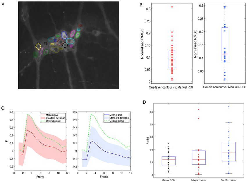
www.nature.com/scientificreports/
to noise) and imaging technologies allow monitoring larger populations of neurons at higher spatiotemporal
resolution4,5. As a result, C a2+ imaging became a powerful tool that provides unique insights in physiologi-
cal behavior of cells and tissues. The power of the method is in the fact that the focus of analysis can be at the
individual cell level as well as on the network of interacting cells. As such it allows studying and understanding
communication between cooperating functional groups of neurons (or other cells) at a high spatiotemporal
resolution6–8.
An extra complexity with live imaging of cells is that they may not be stationary in the microscopic field of
view, either because they traffic themselves or the tissue, in which they are embedded, is contractile. Recordings
in the central nervous system and acute brain slices can be assumed to have static scenes where the only move-
ments present are motion artifacts such as drift, as in brain slices, or cyclic movements, as induced by breathing
in intravital recordings. However, recording activity from tissues with a predominantly contractile function,
such as the heart or the intestine, or from in vivo imaging of awake animals (zebrafish, C. elegans, etc.) presents
unique challenges due to the drastically high level of movement caused by muscle contractions.
In the intestine, all motor activity is controlled by a continuous network of neurons and glia cells embedded in
between two concentric muscle layers. This enteric nervous system (ENS) regulates gut functions such as motility,
secretion, and a bsorption6,9. To understand how the complex circuits in the ENS operate to produce functional
output, it is necessary to record and analyze the activity of large populations of ENS cells. C a2+ imaging is the
optimal tool to achieve this goal. However, the extraction of C a2+ signals from these recordings is an important
bottleneck in the analysis workflow. As a result, a compromise is needed, in which the tissues are prepared (by
removing muscle layers that are innervated by the ENS) or treated (by adding pharmacological compounds), to
limit movement in these recordings and as such facilitate signal e xtraction3,10. In order to derive physiological
information from the tissues in their most intact state, an alternative method for analysis is required.
A traditional analysis workflow in C a2+ imaging starts with image registration of the recorded frames to cor-
rect for motion artifacts and slight underlying movements aiming to attain a completely static scene where each
pixel represents the same physical location throughout all frames11. This step, if successful, is followed by signal
extraction, where the different cells of interest are delineated and their pixel intensity profiles are extracted. For
the large majority of Ca2+ imaging experiments, this workflow is sufficient to efficiently analyze cellular activity
profiles and has been used extensively in ENS C a2+ imaging provided that contractions are restrained either
pharmacologically, physically, or in c ombination12,13.
Multiple different software packages have been developed to automate the signal extraction process and
efficiently analyze the ever-longer recordings and ever-increasing Ca2+ imaging d atasets14,15. However, these
automated analysis workflows also rely on an image registration step and assume that all objects in the image are
spatially static after this step, in order to extract their signals. Contractile movements, as those in the intestine,
can include complex deformations that cannot be compensated with rigid registration techniques. More advanced
non-rigid registration techniques, which offer registration with a high degree of freedom to accommodate more
complex deformations, can be used but they are susceptible to high noise levels and artifacts, two regularly occur-
ring problems in Ca2+ imaging. The tight packing of neurons in small groups (ganglia), with their apparent over-
lap in optical recordings (Fig. 1A), is a first challenge that eliminates the use of classic segmentation workflows.
Moreover, the rapidly oscillating fluorescence of active neurons in Ca2+ imaging (Fig. 1B) has a negative impact
on the success rate of registration algorithms as these rely on pixel intensity or image feature matching and thus
have endogenous problems with changes in intensity12,16,17. ENS C a2+ imaging combines the aforementioned
challenges (Fig. 1C) and thus urges the development of an alternative analysis workflow to delineate and track
individual cells in moving tissues, and extract their signals throughout the recordings.
A viable alternative to registration in these complex scenarios is cell tracking. While tracking techniques
have been extensively used in cell migration analysis and lineage tree c onstruction18–20, the low level-based
segmentation techniques20,21 that are normally used in these applications perform poorly in ENS recordings
since they are prone to noise, variability in the edge intensity due to overlap, and cannot adapt to the blinking
cell appearance between different frames22. The existing region-based tracking techniques are not sufficient to
segment complex structures based on their texture information23,24. Moreover, they are ineffective when dealing
with nonhomogeneous and overlapping objects, such as cells with bright cytoplasm and dark nuclei (Fig. 1A) as
is the case with the expression of the common C a2+ indicator GCaMP. Only one report, by Hennig et. al.25 was
published, in which nucleus tracking of ENS neurons was used, by means of edge detection where dark nuclei
were identified and segmented in each frame to extract fluorescent GCaMP signals from their surrounding pixels.
Practically, manual region-of-interest (ROI) selection remains the most commonly used approach to analyze
ENS recordings, at least for those in which motion can be easily corrected. Recordings that rigid registration
cannot stabilize are routinely disregarded.
Due to its ease of application and flexibility in handling cell division, the main method used in the cell track-
ing field is segmentation, based on implicit functions such as level-sets26–28. However, the large flexibility in this
implicit topological representation can easily produce incorrect results29 especially in low signal to noise ratio
(SNR) recordings. In these situations, explicit functions such as explicit active contours30 perform better as
they depend on parameters and therefore their evolution is more restricted and faster to c alculate31. The main
disadvantage of explicit active surfaces is the inability in handling cell division, which is not relevant in the
specific context of tracking neurons21. In this paper, we implement B-spline-Explicit Active Surfaces (BEAS)
as developed by Barbosa et. al.32 which allows the application of local and global region-based energy terms in
segmentation, as originally developed for level-set segmentation33, while controlling contour smoothness and
keeping the computational cost low32,34. This method is suitable to segment heterogeneous objects (such as cells
with dark nuclei, with varying degrees of brightness and edge clarity, Fig. 1B) and to apply multiple local and
global energy terms to reach that goal.
Scientific Reports | (2021) 11:10937 | https://doi.org/10.1038/s41598-021-90448-4 2
Vol:.(1234567890)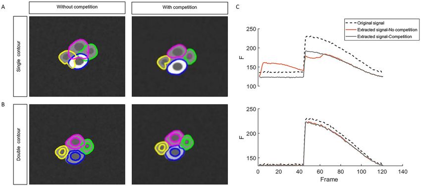
www.nature.com/scientificreports/
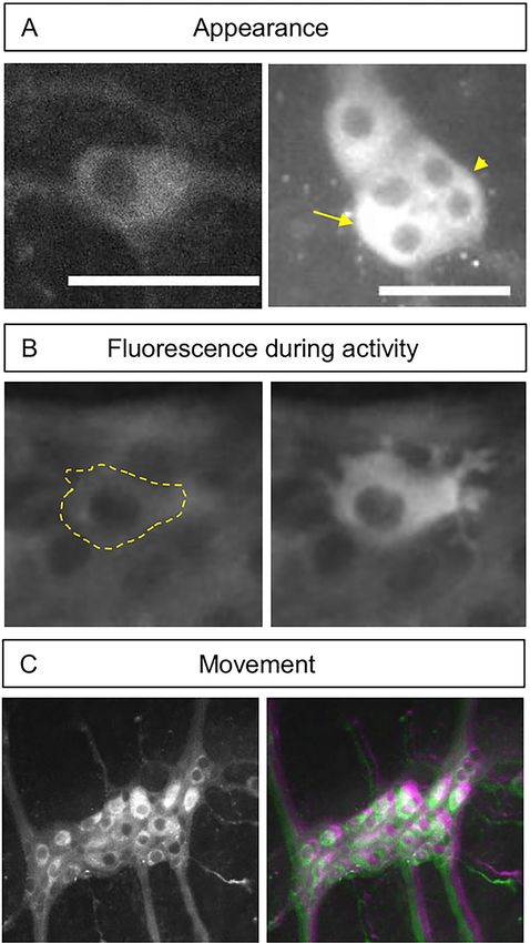
Figure 1. General features of C
a2+ imaging in the ENS. (A) The appearance of an individual GCaMP expressing
enteric neuron when not surrounded by other neurons (Left). The overlapping appearance of enteric neurons
(arrow) and lack of clear borders (arrowhead) (Right). Scale bar represents 50 µm. (B) an example of the
fluorescence signal increases between a neuron at rest (left, and marked with a dashed line) and during activity
(right). C) ENS ganglion (left) containing approximately 20 neurons. Imposed images of different timepoint
(colorcoded in green and magenta) in an ENS Ca2+ recording (1 s. interval between frames). The mismatch in
colors indicates the amount of movement that can be present between 2 frames.
Scientific Reports | (2021) 11:10937 | https://doi.org/10.1038/s41598-021-90448-4 3
Vol.:(0123456789)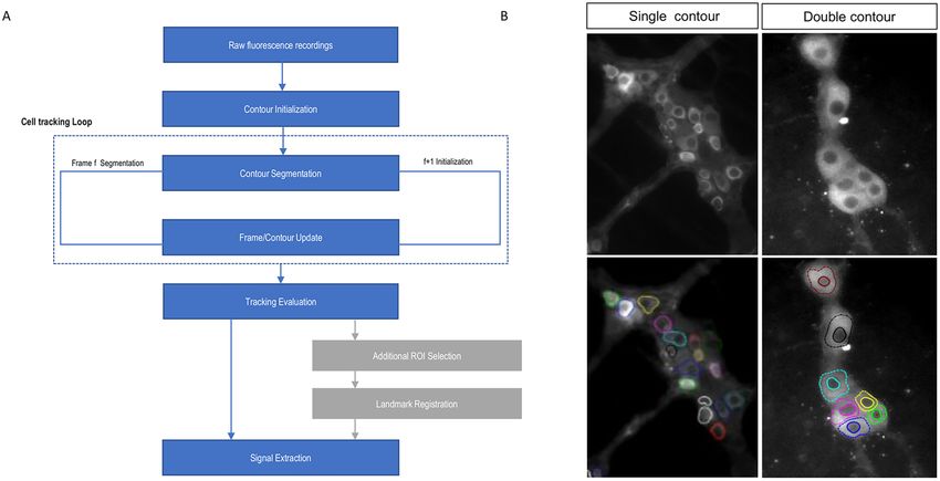
www.nature.com/scientificreports/
Figure 2. (A) diagram of the processing workflow including the main steps of cell tracking (Blue) and the
optional ROI tracking (grey). (B) Example of the performance of the cell tracking procedure of multiple cells in
ENS recordings, using one-layer tracking (left) and double contours (right).
In this paper, we use the BEAS framework on 2D microscopy recordings to track and analyze multiple cells
within a contractile and moving ENS tissue. Apart from employing multiple global and local energy terms to
direct contour evolution, we also use a competition penalty to limit and manage overlap between neighboring
cells. Furthermore, we develop ‘double contour (DC)’ tracking, a novel method that couples the development of
two contour layers and takes advantage of the typical appearance of GCaMP expressing cells. Due to the nuclear
exclusion of GCaMP, these cells present in Ca2+ imaging recordings with a dark nucleus and a bright cytoplasm,
the edges of which are respectively tracked by the two layers. This DC method enables accurate cell tracking
even in the absence of visible external borders. We describe the elements in the C a2+ imaging and cell tracking
algorithm developed and make this information freely available for external use.
In conclusion, we aimed to develop a set of techniques to better extract cellular activity levels from Ca2+ imag-
ing recordings of non-static moving cells (Fig. 2). To this end, we used the ENS as a model system harboring fairly
complex movement and activity-dependent intensity changes. The resulting workflow is however flexible and can
be used to analyze other cellular recordings by tweaking the contour parameters to match the specific application.
Methodology
The workflow for the proposed cell tracking approach starts by drawing an ellipse around the cell to initialize
the contour. This step is followed by deforming the contour iteratively by applying forces on individual contour
control points until the functional energy minimum is reached as an initial segmentation step, which theoreti-
cally overlays the contour with the cell’s boundary. The initialization is followed by the cell tracking loop, which
consists of a series of consequent segmentation tasks on individual frames, where each contour in a frame is
used to initialize the contour’s segmentation on the following frame. During an intermediate step, parametric
information about the contour is calculated and the contour center is also recalculated to be in the geometric
centroid of the produced contour shape to ensure that the new center is inside the cell in each next frame, even
if there was movement between frames (Suppl. Fig. 1). By stringing the segmentation results together, we acquire
both the location of individual cells as well as their contours throughout the entire recording (Fig. 2B).
The goal of this approach is to use these dynamic contours as regions-of-interest (ROIs) from which the mean
a2+ activity of cells in a non-static setting. These contours are
intensity signal is extracted to accurately represent C
then evaluated by the user. Furthermore, the tracked cell locations can also be used as landmarks to optionally
track or displace additional and manually created ROIs, in cases where a tracked cell’s contour was not satisfac-
tory or when tracking additional ROIs posthoc is desired (Fig. 2A).
B‑Spline Explicit Active contours algorithm (BEAS). We implement the B-Spline Explicit Active
Surfaces (BEAS)35 framework developed and optimized for segmenting and tracking heart chambers in
echocardiography34–36. The method uses an explicit function to represent the boundary of an object, where coor-
dinates of the contour points are explicitly given as a function of the remaining coordinates i.e.,x1 = ψ(x2 , . . . , xn )
where ψ is defined as a linear combination of B-spline basis functions
∗
x1 = ψ(x2 , . . . , xn ) = ψ(x ∗ ) = c[k]β d xh − k
(1)
k∈Zn−1
Scientific Reports | (2021) 11:10937 | https://doi.org/10.1038/s41598-021-90448-4 4
Vol:.(1234567890)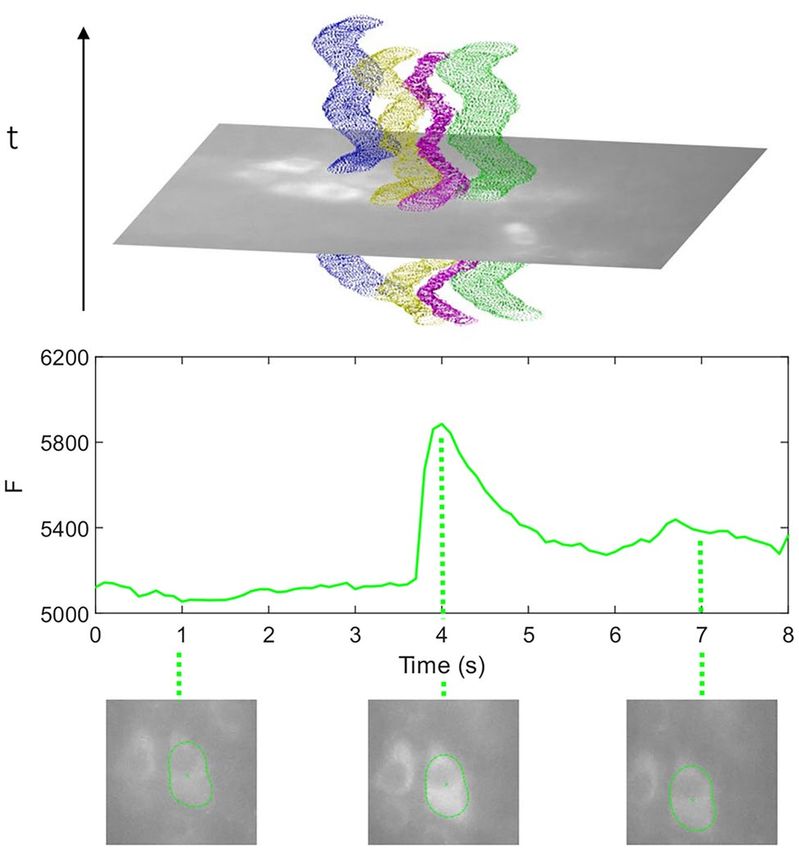
www.nature.com/scientificreports/
where β d (.) is the uniform symmetric B-spline of degree d. The knots of the B-splines are located on a rectangular
grid, with a regular spacing given by h. The coefficients of the B-spline representation are gathered in c[k]. For
this 2D segmentation problem, a polar coordinate system was chosen.
The evolution of the contour is governed by the minimization of the energy term E. This energy has two ele-
ments, the image data term Ed and an internal energy Er.
E = Ed + Er (2)
Data attachment. One‑layer contour. The data attachment energy term in Eq. 2 can be defined, following
the BEAS formulation, as:
Ed = ∫ δφcyt (x) ∫ B x, y · Fcyt y dydx (3)
� �
where Fcyt y is the energy criterion driving the evolution of the contour and B x, y is a mask function in which
the local parameters that drive the evolution are estimated. δφcyt (x) is the Dirac operator applied to
the level set
function φ(x) = Ŵ(x ∗ ) − x1 which is defined over the image domain Ω. The mask function B x, y for a node
(neighborhood radius) is specified as a column of pixels of length ρ in the normal direction centered around a
contour node. The value of ρ is chosen a priori, based on the expected margin (frontier) size between objects
and the rate of movement between frames. When segmenting GCaMP expressing cells, it is logical to set this
parameter to be slightly smaller than the approximate radius of cells, to avoid detecting the cytoplasm-nucleus
edge instead of the intracellular interface. The degree of visibility of a cell’s border in Ca2+ imaging is quite vari-
able as its strength is based on the Ca2+ concentration inside the cell of interest as well as that of adjacent cells.
Moreover, the imaging conditions and imaging system chosen also impact the cell’s appearance (Fig. 1A). There-
fore, we chose a flexible localized energy term introduced by Yezzi et al.37 (Eq. 4), to maximize the difference of
mean intensity inside and outside each contour node.
Fcyt = −(ucyt − uout )2 (4)
where ucyt and uout are the mean intensity values in the cytosolic region (inside the cell) and the region outside
of the cell, respectively.
Double contour. In live fluorescent imaging (eg. in C a2+ imaging), the interface between the bright cytoplasm,
which can be dim if intracellular Ca2+ concentrations are low, and the heterogeneous background may lack con-
trast and as such limit cell tracking capability. GCaMP expressing cells have a bright cell body and a dark nucleus
because the GCaMP molecule molecules do not enter the nucleus. Therefore, a second, and often sharper inter-
face, between the dark nucleus and the bright cytoplasm emerges. This interface is stable and has a predictable
(dark) inner side and (bright) outer side. Therefore, we developed a coupled two-layer active contour segmenta-
tion of cells. The two layers delineate the nucleus-cytoplasm and the cytoplasm-background interfaces, respec-
tively. The inner layer φnuc is delineating the stable shape of the nucleus while the outer contour φcyt attempts
to delineate cell outer borders forming a “double contour”. The image-data energy term in Eq. 2 can instead be
defined as:
Ed = ∫ δφnuc (x) ∫ B x, y · Fnuc y dydx + ∫ δφcyt (x) ∫ B x, y · Fcyt y dydx (5)
� � � �
with Fnuc following Fcyt in its definition (Eq. 4). The double contour produces a more stable contour progression
and keeps the contour attracted to cells in the event of non-visible cellular borders (Fig. 3). It also allows the
extraction of the signal that originates from the cytoplasm pixels only, which improves the signal to noise ratios
of the extracted mean fluorescence.
Data regularization. The energy term Er in Eq. (2) relates to curvature, size, and size difference compared
to the previous frame. We use prior knowledge about the properties of ENS neurons to impose local and global
penalties to guide the contours and ensure that segmentation results and contour shapes will be plausible in their
curvature, size, and size differential between timesteps. The regularization term E
r is defined as:
Er = wκ Eκ + wA EA + wAS EAS (6)
The curvature energy term Eκ limits the negative local mean curvature since cell bodies mostly have positive
curvature. The local curvature gradient term is given by:
∂Eκ ∗ ∗ d x ∗ − k dx ∗
∂cWP [ki ] = ∫ κ(x )H(−κ(x ))β h i (7)
Ŵ
where κ is the local mean curvature which is calculated efficiently as reported within the BEAS framework34,38
and H is the Heaviside function.
The area energy term E A keeps the size of the contour within a reasonable range, where A represents the area
within the contour. The parameters A min and A Max ensure that the contour does not engulf bigger image regions.
The equation for local energy calculation is governed by:
Scientific Reports | (2021) 11:10937 | https://doi.org/10.1038/s41598-021-90448-4 5
Vol.:(0123456789)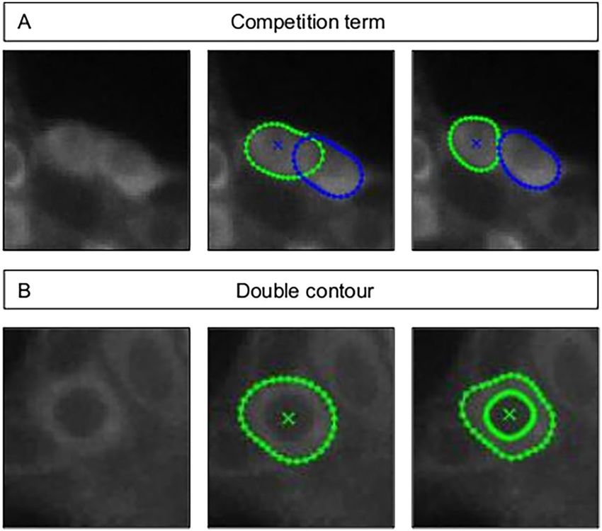
www.nature.com/scientificreports/
Figure 3. The effect of a competition term on neighboring contours (top) The contour of a cell using 1-layer vs
double contour in a GCaMP expressing neuron (bottom).
∂EA
= (A − AMin )H(AMin − A) + (AMax − A)H(A − AMax ) (8)
∂cWA [ki ]
Next, we add the area stability energy term E AS, which is a global energy term that attempts to minimize the
change of the area within the contour keeping its size in a reasonable range for a cell, since apparent size changes
are not real but are due to intensity variations or edge contrast changes and not caused by actual cell size changes.
�At − At−1 �
EAS = (9)
At−1
The weights wκ , wA and wAS in Eq. (6) are chosen by the user based on the morphology and size of the cells
in the image.
Contour competition. It is common for cells in microscopy recordings to appear overlapping, as an image
is a projection of all fluorescent elements in the focus of the objective lens. Especially in widefield microscopy
recordings where images result from many different in- and out-of-focus planes39. This effect is minimized in
confocal and multiphoton excitation approaches, but optical overlap remains an issue due to limited optical
resolution. While banning overlap completely can facilitate interpretation of the extracted data, it does not rep-
resent the scene correctly and can lead to tracking errors. Therefore, we impose a competition penalty that allows
a slight contour overlap to account for the optical overlapping effect while preventing contours from jumping
between cells or engulfing multiple cells. We opted to impose a proximity penalty between neighboring contour
nodes, as implemented previously in BEAS40, to limit contour expansion into neighboring contours and reduce
overlap ( E dist),
dist
(x ∗ ) = dT − ψ i→j .H dT − ψ i→j (10)
Ei→j
where dthresh represents the minimal distance parameter, ψ is a signed distance map between each node of the
contour i against all nodes of contour j (and vice-versa), and H is the Heaviside operator. Note that H equals one
only in nodes with ψ lower than dthresh and zero in the remaining nodes. Therefore, it only applies penalties in
the neighboring regions of the contours40.
We also added a stronger penalty for actual overlap on both contours ( Eoverlap) producing a cell competition
effect controlled by the cell competition weight parameter wc (Fig. 3) that is a priori chosen.
wc Ac i, j , D1 ∩ D2 �= ∅
(11)
Eoverlap i, j =
0, D1 ∩ D2 = ∅
With D1, D2 being the pixels belonging to contour i and j, respectively and Ac is the area of overlap between
two cells. Then, the regularization energy term Er (Eq. 6) can be rewritten to include the competition terms for
a contour i with a neighboring contour j as:
Eri = wκ Eκ + wA EA + wAS EAS + Edist i, j + Eoverlap i, j (12)
Scientific Reports | (2021) 11:10937 | https://doi.org/10.1038/s41598-021-90448-4 6
Vol:.(1234567890)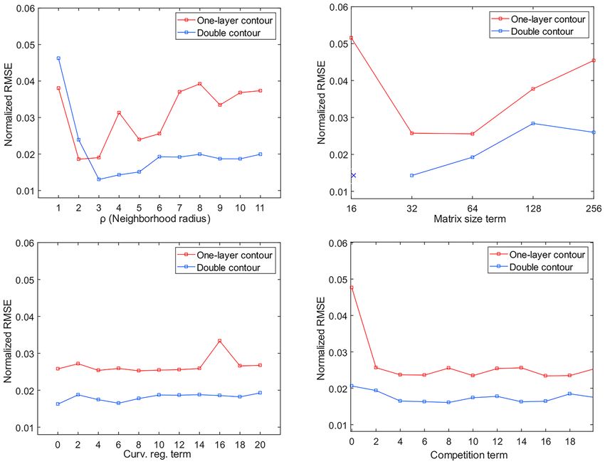
www.nature.com/scientificreports/
The term is incorporated similarly in the energy term E and thus has to be minimized (as in Eq. 2) to find
the optimal contours.
Landmark‑based geometrical transformation and ROI tracking. While we aim at effective cell
tracking in every scenario using BEAS cell tracking, there are known challenges that can constrain tracking
using active contour methods. These challenges include parameter sensitivity causing the algorithm to be subop-
timal for some cells in the field of view, despite being successful for other cells. Therefore, we introduce a robust
optional step that uses the tracked locations of N cell contours using the BEAS approach as landmarks to find
the optimal geometrical transformation T that represents the movement in the recorded scene between frames.
The optimal parameters θ ∗ of T are estimated by minimizing the similarity measure d41,42 which represents the
Euclidian distance of the cell contour coordinates between two frames:
N
f +1 f
θ ∗ = argminθ d(fT , f + 1) = argmin �xi − T xi �2 (13)
i=1
f
With xi being the centroid coordinates x of the contour i in frame f . This geometrical transformation allows
us to move additional ROIs selected manually by the user posthoc throughout the recording frames by perform-
ing the geometrical transformation T 43 on the positions of the ROIs.
Implementation details. Initialization is done by manually selecting ellipses that roughly overlap with
the targeted cell bodies. These ellipses are fed as initial contours to the first frame segmentation step. The result
of contour segmentation in a frame is then used for contour initialization in the next frame. Practically, the
neighborhood radius ρ determines the range of cell movement between frames that is detectable by the segmen-
tation step. ρ is chosen empirically to detect large movements without extending far off the cell edge and losing
its ability in finding local cell edges and relies on multiple parameters including image resolution and relative
movement (Suppl. data). During the initialization step, overlap was not allowed to simplify the initial contour
interactions and limit entanglement in later segmentation steps.
We choose to represent the B-spline contours in polar coordinates because cell bodies appear as closed
ellipses. Therefore, the geometry functions took the form of r = ψ(θ). The geometrical center of the contour
shape is calculated and the pole of the contour coordinates translated to this point after each time step (Suppl.
Fig. 1). This step is essential as contours cannot be represented as a polar curve if the pole (coordinates’ origin)
is outside of the cell contour.
The angular discretization factor denoting contour boundary nodes was set empirically to 32 nodes with regu-
lar angular interval dθ. When applied to the experimental recordings, this setting was found to provide a good
balance between shape flexibility and representation at a reasonably low computational cost. We measured its
effect and that of other parameters in a dedicated parameter sensitivity test. New contour nodes were resampled
after the translation step to preserve the accuracy levels of the discretization and maintain the regular interval
dθ. This was done by using linear interpolation of the contour nodes’ coordinates (r`, θ`) for polar angles θ`
with a regular dθ interval.
A modified gradient descent with feedback step-adjustment was used to perform the energy criterion mini-
mization as explained in previous BEAS i mplementations16,35. After implementation in MATLAB (ver. R2020b)
Runtime was linearly dependent on the number of cells and the image size. The geometrical transformations
T used in landmark-based ROI tracking is implemented in the form of a polynomial affine transformation44.
Results
Segmentation strategy evaluation. To objectively evaluate the presented segmentation strategies, we
created an artificial dataset that simulates the C a2+ imaging scenes, featuring movement at rates similar to what
is measured in ENS recordings, several intensity-change patterns that represent C a2+ activity, overlapping neigh-
boring cells with similar baseline intensities, and multiple blurred frames to mimic out-of-focus imaging frames
(Fig. 4).
We analyzed the signals in this dataset using four different approaches and compared how the extracted
signals matched the ground truth signals. Using one-layer segmentation which targets the cytoplasmic border
only, without the competition term, expectedly yields poor results, with contours overlapping significantly as
the contour nodes cannot find clear edges or intensity gradients (Fig. 4A, left). As a result, the extracted signals
are contaminated with information from neighboring cells. On the other hand, using the competition term in
addition to the fixed global curvature term anchors the contours and restricts their shapes to prevent them from
taking over neighboring cells (Fig. 4A, right), which improves the extracted signal quality drastically. In contrast,
the double contour segmentation maintains the general shape even without a competition penalty due to the
coupling between the two segmentation layers although a slight overlap can be observed. The small overlaps, in
this case, are alleviated when the competition term is added (Fig. 4B).
Signals extracted from the artificial dataset confirm that one-layer contour tracking, without competition, is
not reliable in extracting the original signal. This is shown in Fig. 4C top, where the activity from the neighboring
cell appears in the activity trace of the measured cell (Fig. 4C, top row, red trace). Double contour segmentation
and one-layer contours with competition terms, have no such issues and allow extraction of an accurate signal
shape. This is especially the case for double contour segmentation, where the raw fluorescence level is closer to
the original because now the dark nucleus pixels can be excluded from the calculation of the cytoplasm intensity
(Fig. 4C, bottom).
Scientific Reports | (2021) 11:10937 | https://doi.org/10.1038/s41598-021-90448-4 7
Vol.:(0123456789)www.nature.com/scientificreports/
Figure 4. Tracking of overlapping cells with the same base intensity level during rest and different intensity
levels during activity using (A) one-layer contours without a competition parameter (left) and with a
competition penalty added (right) and (B) double contours without a competition parameter (left) and with a
competition penalty added (right) (C) Extracted signals from a cell using one-layer contours (top) and double
contours (bottom).
Parameter sensitivity analysis in an artificial dataset. The impact of each of the selected parameters
on segmentation and tracking results using active contours in both one-layer and the double contour methods
are estimated by calculating the mean Root Mean-Square Error (RMSE), which is a measure of the difference
between observed values and a reference, and in this case, between the extracted signals and reference or ground
truth signals. (Fig. 5).
The first parameter ρ, the neighborhood radius (Fig. 5, top left), expectedly has, for smaller values, a big
influence on the tracking results. Afterwards, the tracking is stable for several values until the radius is too large
and tends to encounter multiple edges simultaneously. The second parameter, the matrix size, which determines
the number of discretized contour nodes negatively affects the tracking at smaller matrix sizes (fewer num-
ber of nodes) for both one- and double contour tracking, with failure to track cells in case of double contour
segmentation with the lowest (only sixteen) number of nodes (Fig. 5, top right). This indicates that due to its
extra complexity, double contour segmentation is more sensitive to the number of nodes. While the curvature
term does not affect the accuracy of segmentation (Fig. 5, bottom left), the addition of a competition term does
improve segmentation, especially for the one-layer segmentation option. The effect of a competition term with
double contour segmentation is negligible in this dataset (Fig. 5, bottom right).
Experimental results. When applied to actual recordings, we find that the proposed approach successfully
tracks cells throughout significant tissue movements (Fig. 6, Top panel), allowing us to reliably resolve Ca2+
peaks from the extracted signals (Fig. 6, bottom panel).
To compare with traditional analysis methods, we analyzed recordings with both the new contour tracking
method as well as with manual routines, involving motion correction and rectangular ROI selection by a blinded
expert. For that purpose, we used datasets of 3 recordings to compare the degree of similarity of the signals
extracted by the traditional method against the one-layer contour and double contour methods, respectively
(Fig. 7A,B). We found that Ca2+ profiles are very comparable in shape between extraction from tracked cells
versus manually drawn ROIs, with a normalized root-mean-square error (RMSE) of 0.093 and 0.114 for one-
layer or double contours respectively (Fig. 7B).
True validation of our analytical approach is not straightforward as it requires assessing the quality of signal
extraction against a ground truth signal. Since the latter should be fully known, yet embedded in a context that
holds all the biological, optical, and experimental complexity, we generated artificial Ca2+ peaks in real Ca2+
recordings in the cytoplasm of multiple moving cells (Suppl. movie 1). Then we used the contour cell tracking
method to re-extract the Ca2+ signals and compared the extracted signals to the original planted signal. We found
that the Ca2+ peak shape was preserved in most cells (Fig. 7C), and the median RMSE in the one-layer and double
contour approach to be 0.1216 and 0.1738 (based on 22 tracked cells) to be comparable to that of the manually
selected ROIs with an RMSE of 0.1212 (Fig. 7D). The higher RMSE values of DC tracking are simply due to a
few complete tracking failures, see Discussion.
Finally, we used the newly developed tracking approach on actual recordings of ENS tissue (Suppl. movies
22, 3) including movement in x and y and out-of-focus frames. We found that with optimized parameters one-
layer segmentation, proves reliable to track many cells in the field of view. Notably, the segmentation procedure
performs well despite the presence of blurry out-of-focus frames (Fig. 7), which is an important advantage
compared to edge-based segmentation t echniques45. In double contour segmentation, we observed less overlap
of contours without a competition penalty resulting in good reliability in cells with non-visible edges. However,
this method had more difficulties in scenes with faster movement and was expectedly not robust in cells without
Scientific Reports | (2021) 11:10937 | https://doi.org/10.1038/s41598-021-90448-4 8
Vol:.(1234567890)www.nature.com/scientificreports/
Figure 5. Parameter sensitivity analysis: comparison between one-layer vs. double contours where the Y-axis
is the normalized RMSE of the extracted signals compared to the raw signals: (top left) effect of radius length
values on segmentation sensitivity, double contour segmentation has less segmentation error for all values in the
relevant range > 3. (top right) effect of the number of contour nodes: higher RMSE for one-layer segmentation
for all values, note the segmentation failure of double contour method at low (e.g. sixteen) contour nodes
number, as indicated with x. Curve regulation term (bottom left). Competition term (bottom right): lack of
competition term causes high normalized-RMSE for one-layer segmentation.
contrast between the nucleus and cytoplasm. While this new approach performs well, it is unavoidable that cell
tracking fails to resolve some cells with challenging appearance or location in the image. The developed landmark
ROI-tracking exploiting the known trajectory of successfully-tracked cells proved to be a useful and robust tool
to overcome this challenge with minimal computational power needed (Suppl. movie 4). In addition, it gives
the researcher the additional ability to extract signals from smaller structures, like cell processes or glial cells
(Fig. 7A).
Discussion
Given the complexity of C a2+ imaging in the contractile ENS tissues, where a scene not only contains moving
cells but these cells also display irregular fluorescence intensity changes11, traditional methods based on image
registration and ROI selection are cumbersome and prone to failure during signal extraction and quantitative
analysis3,10,46,47. Additionally, low-level cell tracking techniques cannot function reliably in this scenario due
to multiple reasons, including low signal-to-noise ratio (often the case in live imaging), cellular overlap and
variable cellular edges, which depend both on the imaging system and the labeling approach, as well as on the
activity of the c ell48. In this paper, we developed a cell tracking algorithm targeted specifically to track neurons
in such a challenging contractile scenario, with the additional complexity that cells in C a2+ imaging have blurry
borders and constantly change fluorescence intensity. Our method successfully tracks blinking cells in moving
ENS tissue, without the need for non-rigid image registration. The extracted temporal signals are comparable in
quality to manual, expert-selected ROIs. Furthermore, the tracked cell coordinates allow additional rectangular
ROI tracking and add robustness and flexibility to the workflow to process the most challenging recordings.
Comparison of segmentation strategies. In an artificial dataset that was created to simulate cell shape
and behavior, specifically having moving cells without clear borders, we found the competition term to be
important in one-layer cell tracking as the contours overlap and the contour nodes do not find edges to adhere
to in their absence. The addition of a competition term and a significant curvature term prevents them from tak-
ing over neighboring cells resulting in good signal extraction.
Scientific Reports | (2021) 11:10937 | https://doi.org/10.1038/s41598-021-90448-4 9
Vol.:(0123456789)www.nature.com/scientificreports/
Figure 6. Contours of multiple cells and cell movement (top). Pixel intensity signal from the one tracked cell in
the top panel and the contour appearance at multiple time points before, during and after a peak in C a2+ activity.
Figure 7. (A) Contours of tracked cells and manual rectangular ROIs which are moved based on the contours
tracked. (B) RMSE of signals extracted using 1 layer (red) and double contour (blue) versus manually selected
ROIs by an expert. (C) Comparison of the extracted signals (red/blue mean, light red/blue standard deviation)
against a ground truth artificial peak (dotted green) using 1-layer contour tracking (left) and double contours
(right) based on 22 cells. (D) RMSE of signals extracted from 22 cells injected with the artificial peak using
manual ROIs (left), 1 layer (center) and double contour (right) versus the ground truth.
Scientific Reports | (2021) 11:10937 | https://doi.org/10.1038/s41598-021-90448-4 10
Vol:.(1234567890)www.nature.com/scientificreports/
The performance of cell segmentation in this simulated dataset is consistently improved by using the novel
double contour method. The double contour uses the inner nucleus contours as a natural anchor that restricts
the outer contour from taking over neighboring cells. It can conserve the shape with low, or even without,
competition and curvature terms. However, the advantage of the coupled double contour approach is limited in
recordings with large cell displacement between frames as it depends on tracking the smaller nucleus from its
position in the previous frame. In this case, higher image acquisition rates are required, which adds complexity
to the imaging setup, generates bigger datasets, and causes longer processing times. Nevertheless, we consider
the double contour approach to be powerful in its application to GCaMP based recordings, as the reporter is
genetically prevented from entering the nucleus, leaving the nucleus dark and thus enabling accurate tracking
of cells and signal extraction selectively from the cytoplasm.
Parameter sensitivity analysis. Active contours are heavily reliant on multiple parameters and can be
sensitive to parameter values limiting their robustness. Segmentation and tracking results are reliant on the
values of multiple parameters controlled by the user. This means that a minimal understanding of how they
might affect the final outcome is required49, which is a drawback of all parametric segmentation models. There-
fore, we quantified the effects of the global penalty terms on the algorithm’s performance in both the one-layer
and double contour strategies, by extracting and comparing the signals from simulated data. We observed gen-
eral similarity in sensitivity to the studied parameters, except for the inability to track cells when using only a
few contour nodes in the double contour, which is at odds with the increased complexity of this strategy. The
introduction of the cell competition term improved cell tracking when using one-layer contours, reduced the
error rate to similar values as obtained by double contours in this dataset. Although the curvature term did not
increase the accuracy of the extracted signal in the simulated dataset, it plays an important stabilizing role to the
cell contours in real recordings, especially in blurred images or in frames where segmentation is struggling to
delineate cells returning to baseline fluorescence. We found that tracking is generally insensitive to a wide range
of parameter values in the simulated dataset despite our efforts to introduce the most challenging conditions,
which all together indicate that the performance of the algorithm is robust.
In general, the global penalty terms are valuable to limit segmentation failure, which is a known drawback
of active contour s egmentation33. However, they do not show significant effects on tracking results of cells that
are already well within the means of the method, as shown in Fig. 5.
Experimental results. As the aim of the new approach was to extract accurate C a2+ signals from experi-
mental data, we compared contour tracking to the traditional extraction method and found a high similarity
of the extracted signals between the two methods. We used an artificially embedded C a2+ peak to measure the
similarity to the ground truth and found that these planted peaks were indeed detected in most cells, demon-
strating the applicability of the contour tracking workflow. The artificially embedded Ca2+ peaks were then used
to compare the quality of the signal extraction using the two contour types against the traditional extraction
method. Results from the one-layer contours were highly similar to those of the traditional method in their
error between the extracted signal and the ground truth values of the artificial peak (Fig. 7). We observed slightly
lower average similarity between the ground truth signal and double contour method, which was mainly due to
instances where the method failed to track those neurons without contrast between the nucleus and cytoplasm,
which we, in order to be as close to reality as possible, also included in the dataset. This is easily mitigated by
using the additional ROI tracking option, which we introduced to extract signals from cells for which contour
tracking is inaccurate (Fig. 2A).
Practically, we find one-layer tracking to be robust in recordings with blurry out-of-focus frames and its
stability largely depends on the neighborhood radius ρ in relation to movement intensity in-between frames.
Furthermore, the introduction of a cell competition term improves cell tracking and reduces the error in experi-
mental recordings. Double contour tracking on the other hand is useful when the recording is not blurry and
the movement in-between frames is generally less than the nucleus diameter. The latter limits the applicability in
recordings with substantial displacement due to rapid muscle contractions, especially when fast image acquisi-
tion is not feasible. Its main advantage, which results from the inner nucleus contour acting as an anchor to the
outer cellular contour, is the ability to track overlapping cells without clearly visible borders, a common sight
for ENS neurons in the submucosal l ayer6. Therefore, the two methods are complementary and can be used by
subjectively assessing the recording at hand. The landmark-based ROI tracking possibility for manually-added
ROIs provides a useful addition that allows tracking challenging cells, which the active contours method fails
to correctly segment. It is a useful tool as it does not require re-running the tracking workflow and is applied
post-hoc, providing a robust option fully controlled by the user. Compared to activity-based signal extraction
methods used in C a2+ imaging, which require successful image registration and completely static scenes to then
provide Ca2+ signals from active cellular regions50,51, this method allows for efficient analysis of Ca2+ imaging
datasets with a non-static scenery regardless of the effectiveness of image registration.
The method developed by Hennig et al.10, specifically for ENS tissue requires image thresholding of the bright
cytoplasm-dark nuclei interface to segment nuclei and extract signals, which is suitable for non-blurry record-
ings of the bright GCaMP3 C a2+ indicator10. In contrast, we are able to successfully track cells in partially-blurry
recordings and using the more dynamic, but dimmer at rest, C a2+ indicator GCaMP6f. This helps us in analyzing
faster neuronal activity and detecting the C a2+ transients elicited by individual action p otentials52.
Scientific Reports | (2021) 11:10937 | https://doi.org/10.1038/s41598-021-90448-4 11
Vol.:(0123456789)www.nature.com/scientificreports/
Conclusion
a2+ imaging in moving and contractile tissues, we introduced an
To satisfy the need for a robust analysis tool for C
efficient hybrid approach to track cell bodies relying on local region-based terms in evolving the contour, avoid-
ing the disadvantages of region-based segmentation (Fig. 2). We further developed a novel ‘double contour’ or
coupled-layers tracking algorithm that takes advantage of the fact that cells in genetically encoded Ca2+ imaging
techniques appear with dark nuclei. We quantified the method’s performance in an artificial dataset that simulates
experimental challenges under different parameter values and compared the two tracking algorithms. We then
tested the algorithm’s robustness in tracking neurons in various ENS tissue C a2+ recordings and demonstrate,
using embedded artificial C a2+ spikes, that the method reliably captures these spikes and represents them in
the extracted signals. We expanded the analysis possibilities by implementing land-mark based ROI tracking,
which increases the robustness of the workflow for challenging datasets. Finally, we packaged the workflow as
a MATLAB GUI to enable efficient analysis of Ca2+ imaging datasets with a non-static scenery. This novel cell
tracking method uses multiple features of ENS neurons activity and appearance to effectively segment, track and
extract the C a2+ signals from complex and biologically relevant recordings. It has the explicit advantage that it
can deal with dramatically changing intensities, even when very dim and hardly above noise levels. Moreover,
the technique behaves robust even if out-of-focus frames are present in the recordings. Even though the ENS
was used as a model system, the technique can still be used on other cellular recordings by tweaking the contour
parameters to match the specific application.
Received: 4 January 2021; Accepted: 6 May 2021
References
1. Chen, Y. et al. Structural insight into enhanced calcium indicator GCaMP3 and GCaMPJ to promote further improvement. Protein
Cell 4, 299–309 (2013).
2. Grienberger, C. & Konnerth, A. Imaging Calcium in Neurons. Neuron 73, 862–885 (2012).
3. Li, Z. et al. Regional complexity in enteric neuron wiring reflects diversity of motility patterns in the mouse large intestine. Elife
8, e42914 (2019).
4. Yang, W. et al. Simultaneous multi-plane imaging of neural circuits. Neuron 89, 269–284 (2016).
5. Chisholm, K. I., Khovanov, N., Lopes, D. M., La Russa, F. & McMahon, S. B. Large scale in vivo recording of sensory neuron activity
with GCaMP6. eNeuro https://doi.org/10.1523/ENEURO.0417-17.2018 (2018).
6. Fung, C. & VandenBerghe, P. Functional circuits and signal processing in the enteric nervous system. Cell. Mol. Life Sci. 77, 4505
(2020).
7. Russell, J. T. Imaging calcium signals in vivo: a powerful tool in physiology and pharmacology. Br. J. Pharmacol. 163, 1605–1625
(2011).
8. Harel, A. & Ryan, T. The memory toolbox: how genetic manipulations and cellular imaging are transforming our understanding
of learned information. Curr. Opin. Behav. Sci. 32, 136–147 (2020).
9. Furness, J. B. The enteric nervous system and neurogastroenterology. Nat. Rev. Gastroenterol. Hepatol. https://doi.org/10.1038/
nrgastro.2012.32 (2012).
10. Hennig, G. W. et al. Use of genetically encoded calcium indicators (GECIs) combined with advanced motion tracking techniques
to examine the behavior of neurons and glia in the enteric nervous system of the intact murine colon. Front Cell Neurosci. 9, 436.
https://doi.org/10.3389/fncel.2015.00436/abstract (2015).
11. Boesmans, W., Hao, M. M. & Vanden, B. P. Optical tools to investigate cellular activity in the intestinal wall. J. Neurogastroenterol.
Motil. 21(3), 337–351 (2015).
12. Pnevmatikakis, E. A. & Giovannucci, A. NoRMCorre: an online algorithm for piecewise rigid motion correction of calcium imag-
ing data. J. Neurosci. Methods 291, 83–94 (2017).
13. Boesmans, W. et al. Imaging neuron-glia interactions in the enteric nervous system. Front Cell Neurosci. 7, 183 (2013).
14. Romano, S. A. et al. An integrated calcium imaging processing toolbox for the analysis of neuronal population dynamics. PLOS
Comput. Biol. 13(6), e1005526. https://doi.org/10.1371/journal.pcbi.1005526 (2017).
15. Maruyama, R. et al. Detecting cells using non-negative matrix factorization on calcium imaging data. Neural Netw. 55, 11–19
(2014).
16. Kybic, J. & Unser, M. Fast parametric elastic image registration. IEEE Trans. Image Process. 12, 1427–1442 (2003).
17. Sorokin, D. V., Peterlik, I., Tektonidis, M., Rohr, K. & Matula, P. Non-rigid contour-based registration of cell nuclei in 2-D live cell
microscopy images using a dynamic elasticity model. IEEE Trans. Med. Imaging 37, 173–184 (2018).
18. Hilsenbeck, O. et al. Software tools for single-cell tracking and quantification of cellular and molecular properties. Nat. Biotechnol.
34, 703–706 (2016).
19. Bise R, Kanade T, Yin Z, Huh SIL. Automatic cell tracking applied to analysis of cell migration in wound healing assay. In: Proceed-
ings of the Annual International Conference of the IEEE Engineering in Medicine and Biology Society, EMBS. 2011.
20. Chen, X., Zhou, X. & Wong, S. T. C. Automated segmentation, classification, and tracking of cancer cell nuclei in time-lapse
microscopy. IEEE Trans. Biomed. Eng. 53, 762–766 (2006).
21. Dufour A, Olivo-Marin JC. Tracking live cells in 4D microscopy: From active surfaces to active meshes. In: Conference Record -
Asilomar Conference on Signals, Systems and Computers. 2008.
22. Chenouard, N. et al. Objective comparison of particle tracking methods. Nat. Methods 11(3), 281–289. https://doi.org/10.1038/
nmeth.2808 (2014).
23. Rizk, A. et al. Segmentation and quantification of subcellular structures in fluorescence microscopy images using Squassh. Nat.
Protoc. 9(3), 586–596. https://doi.org/10.1038/nprot.2014.037 (2014).
24. Ta, V. T., Lézoray, O., Elmoataz, A. & Schüpp, S. Graph-based tools for microscopic cellular image segmentation. Pattern Recognit.
42, 1113–1125 (2009).
25. Hennig, G. W. et al. Use of genetically encoded calcium indicators (GECIs) combined with advanced motion tracking techniques
to examine the behavior of neurons and glia in the enteric nervous system of the intact murine colon. Front Cell Neurosci. https://
doi.org/10.3389/fncel.2015.00436 (2015).
26. Padfield, D., Rittscher, J., Thomas, N. & Roysam, B. Spatio-temporal cell cycle phase analysis using level sets and fast marching
methods. Med. Image Anal. 13(1), 143–155 (2009).
27. Dzyubachyk, O., Van Cappellen, W. A., Essers, J., Niessen, W. J. & Meijering, E. Advanced level-set-based cell tracking in time-lapse
fluorescence microscopy. IEEE Trans. Med. Imaging 29, 852–867 (2010).
Scientific Reports | (2021) 11:10937 | https://doi.org/10.1038/s41598-021-90448-4 12
Vol:.(1234567890)www.nature.com/scientificreports/
28. Chan, T. F. & Vese, L. A. Active contours without edges. IEEE Trans. Image Process. 10, 266–277 (2001).
29. Dufour, A. et al. Segmenting and tracking fluorescent cells in dynamic 3-D microscopy with coupled active surfaces. IEEE Trans.
Image Process. 14, 1396–1410 (2005).
30. Ray, N., Acton, S. T. & Ley, K. Tracking leukocytes in vivo with shape and size constrained active contours. IEEE Trans. Med.
Imaging 10, 1222–1235 (2002).
31. Dufour, A., Thibeaux, R., Labruyère, E., Guillén, N. & Olivo-Marin, J. C. 3-D active meshes: fast discrete deformable models for
cell tracking in 3-D time-lapse microscopy. IEEE Trans. Image Process. 20, 1925 (2011).
32. Barbosa, D. et al. B-spline explicit active surfaces: an efficient framework for real-time 3-D region-based segmentation. IEEE Trans.
Image Process. 21, 241–251 (2012).
33. Chen, A., Deeley, M. A., Niermann, K. J., Moretti, L. & Dawant, B. M. Combining registration and active shape models for the
automatic segmentation of the lymph node regions in head and neck CT images. Med. Phys. 37, 6338–6346 (2010).
34. Pedrosa, J. et al. Left ventricular myocardial segmentation in 3-D ultrasound recordings: effect of different endocardial and epi-
cardial coupling strategies. IEEE Trans. Ultrason. Ferroelectr. Freq. Control 64(3), 525–536 (2017).
35. Barbosa, D. et al. Fast and fully automatic 3-D echocardiographic segmentation using B-spline explicit active surfaces: feasibility
study and validation in a clinical setting. Ultrasound Med. Biol. 39, 89–101 (2013).
36. Barbosa D, Bernard O, Heyde B, Dietenbeck T, Houle H, Friboulet D, et al. B-spline explicit active tracking of surfaces (BEATS):
Application to real-time 3D segmentation and tracking of the left ventricle in 3D echocardiography. In: IEEE International Ultra-
sonics Symposium, IUS. 2012. p. 224–7.
37. A Fully Global Approach to Image Segmentation via Coupled Curve Evolution Equations. J Vis Commun Image Represent [Inter-
net]. 2002 Mar 1 [cited 2017 Sep 25];13(1–2):195–216. Available from: http://www.sciencedirect.com/science/article/pii/S1047
320301905000
38. Solomon B, Gray A. Modern differential geometry of curves and surfaces. Am Math Mon. 2006;
39. Mohammed, A. I. et al. An integrative approach for analyzing hundreds of neurons in task performing mice using wide-field
calcium imaging. Sci. Rep. https://doi.org/10.1038/srep20986 (2016).
40. Morais, P. et al. A competitive strategy for atrial and aortic tract segmentation based on deformable models. Med. Image Anal. 42,
102–116 (2017).
41. Johnson, H. J. & Christensen, G. E. Consistent landmark and intensity-based image registration. IEEE Trans. Med. Imaging 21,
450–461 (2002).
42. Broit C. Optimal registration of deformed images. Optimal registration of deformed images. 1981.
43. Bogovic JA, Hanslovsky P, Wong A, Saalfeld S. Robust registration of calcium images by learned contrast synthesis. In: Proceed-
ings—International Symposium on Biomedical Imaging. 2016.
44. Goshtasby, A. Piecewise linear mapping functions for image registration. Pattern Recognit. 19, 459–466 (1986).
45. Grǎdinaru, C. et al. Assessment of automated analyses of cell migration on flat and nanostructured surfaces. Comput. Struct.
Biotechnol. J. Res. Netw. Comput. Struct. Biotechnol. 1, e201207004 (2012).
46. Hennig, G. W. Spatio-temporal mapping and the enteric nervous system. In Advances in experimental medicine and biology (eds
Brierley, S. & Costa, M.) (Springer, Cham, 2016).
47. Hennig, G. W. et al. ICC-MY coordinate smooth muscle electrical and mechanical activity in the murine small intestine. Neuro‑
gastroenterol. Motil. https://doi.org/10.1111/j.1365-2982.2009.01448.x (2010).
48. Ulman, V. et al. An objective comparison of cell-tracking algorithms. Nat. Methods. 14, 1141–1152 (2017).
49. Bresson, X., Esedoglu, S., Vandergheynst, P., Thiran, J. P. & Osher, S. Fast global minimization of the active contour/snake model.
J. Math. Imaging Vis. 28, 151–167 (2007).
50. Mukamel, E. A., Nimmerjahn, A. & Schnitzer, M. J. Automated analysis of cellular signals from large-scale calcium imaging data.
Neuron 63(6), 747–760 (2009).
51. Giovannucci, A. et al. CaImAn an open source tool for scalable calcium imaging data analysis. Elife 8, e38173 (2019).
52. Chen, T. W. et al. Ultrasensitive fluorescent proteins for imaging neuronal activity. Nature 499, 295–300 (2013).
Acknowledgements
The authors thank Tobie Martens for manual cell delineation and ROI selection on C a2+ recordings. such there
was no direct use of animal tissues for this study. All microscopy recordings in this study were re-used recordings
from previous projects performed according to the guidelines and procedures as approved by the Animal Ethics
committee of KU Leuven. The authors’ work is supported by the Research Foundation Flanders (FWO) grant
G.0929.15, G.OH1816N and I001918N and Hercules AKUL/11/37 and AKUL/15/37 (to P.V.B.).
Author contributions
Y.K., J.P. and P.V.B. contributed to conceptualization and methodology, W.B. contributed to data curation, Z.Z.,
W.B., J.d.H. and P.V.B. contributed to validation and manuscript editing. All authors reviewed the manuscript.
Competing interests
The authors declare no competing interests.
Additional information
Supplementary Information The online version contains supplementary material available at https://doi.org/
10.1038/s41598-021-90448-4.
Correspondence and requests for materials should be addressed to P.V.B.
Reprints and permissions information is available at www.nature.com/reprints.
Publisher’s note Springer Nature remains neutral with regard to jurisdictional claims in published maps and
institutional affiliations.
Scientific Reports | (2021) 11:10937 | https://doi.org/10.1038/s41598-021-90448-4 13
Vol.:(0123456789)You can also read