Evaluation of simulation results using Augmented Reality
←
→
Page content transcription
If your browser does not render page correctly, please read the page content below
12th European LS-DYNA Conference 2019, Koblenz, Germany

  Evaluation of simulation results using Augmented
                        Reality
                         Michael Lechner1, Robert Schulte1, Marion Merklein1,

                                 Institute of Manufacturing Technology

                          Friedrich-Alexander-Universität Erlangen-Nürnberg

                           Egerlandstraße 13 – 91058 Erlangen – Germany

1 Abstract
Simulation has become an important tool in order to design forming processes in a time and cost
efficient way. However, simulation results are almost exclusively visualized using conventional laptops
or personal computers. Especially, in the press shop an analysis directly at real parts is not possible at
the moment. At the same time, there has been a very convincing development in the field of
Augmented Reality hardware in recent years. In particular, the iPhone and the iPad of the company
Apple as well as the HoloLens of the company Microsoft offer interesting solutions for the industry.
Thereby, the Augmented Reality applications are until now limited to CAD-data or assembly problems.
Therefore, within scientific contribution a method to visualize simulation results from LsDyna in a
simple way is presented. It will be explained, how new simulation results can be loaded on runtime
and which use cases can be derived with the technology. In the end, Augmented Reality solutions with
HoloLens as well as iPhone/iPad will be compared and evaluated.

2 State of the Art - Augmented Reality
The simulation process can be divided into pre-processing, solving and post-processing. While
extensive efforts have been made in recent years to advance the pre-processing as well as solving for
example by new material models or enhanced mesh description, there was only a small development
in the area of result visualisation. Augmented Reality offers a promising opportunity to improve the
post-processing of simulation results and, in particular, to provide a method that allows laypersons
without prior knowledge to quickly and easily take advantage of improved visualization. According to
recent studies by VENKATESCH [1], the acceptance and adaptation of technology essentially depend
on their accessibility. Within this context, Augmented Reality is estimated to have a market size of
about 200 billion Dollar in 2022.
At the moment, Augmented Reality is mainly used for assembly applications. In this context,
Augmented Reality technology offers great potential for optimizing robot operation and programming.
An AR-based interface allows the overlay of real-time transmission of the workstation with information
about the work of the robot. The visualization of work paths and, for example, gripping operations
facilitates the interaction between the robot and the operator. The use of AR tracking systems
provides moreover a new intuitive way for manual web programming of robots. Thereby, the
programmer leads a tracking tag by hand along the desired robot path. The web is analyzed by the
optical position detection of the tracking mark and displayed in the Augmented Reality. The execution
of the taught-in movement is then visualized using a virtual robot model in the real work environment.
The Augmented Reality is displayed either via a head-mounted display (HMD) or on a computer
screen. The topic of robot programming with AR support is described e.g. from PETTERSEN ET AL.
[2], GASCHLER [3], PAI ET AL. [4] and CATCH ET AL. [5]. The use of Augmented Reality also
extends the possibilities of remote control of robots. MARIN ET AL. [7] and JARA ET AL. [8] present
AR web applications for controlling robots over the internet in their contributions.
Concerning hardware for commercial applications, Apple has at the moment with its smartphones and
tablets a leading role for enterprises. While Mac computers have not prevailed in the industry to this
day, for security reasons companies are primarily using iPhones and iPads with the iOS operating
system. Nearly 79% of mobile systems now use Apple's operating system iOS [9]. Of the devices,
66% are iPhones and 34% are iPads. In the case of Augmented Reality glasses the Microsoft
HoloLens, which was launched in January 2015, can be seen as a milestone in Augmented Reality

                               © 2019 Copyright by DYNAmore GmbH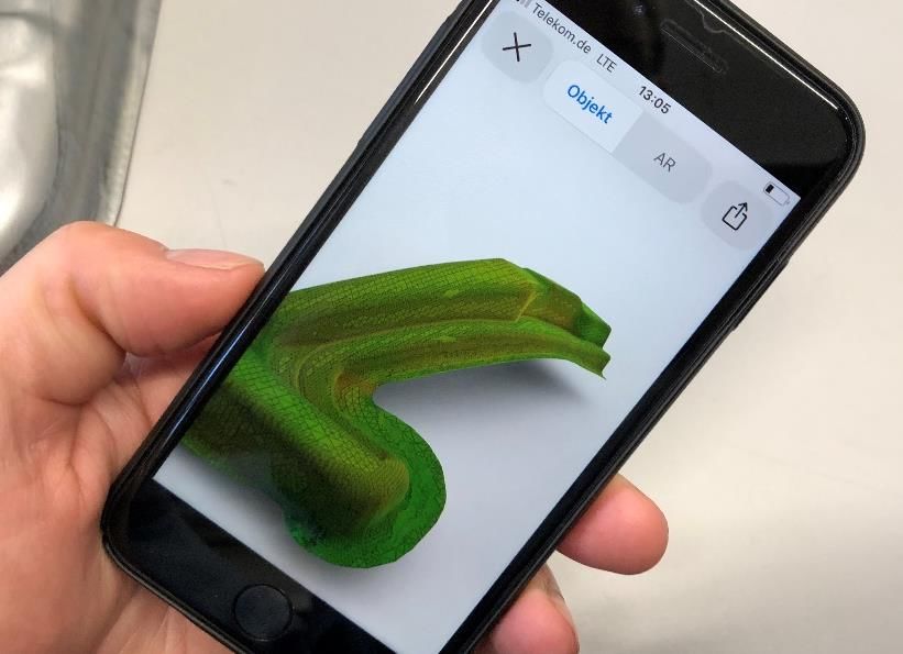
12th European LS-DYNA Conference 2019, Koblenz, Germany

and Mixed Reality technology. The HoloLens is the first portable autonomous AR system that, despite
its comprehensive functionality, can be used as a mobile device and independent of additional
devices. Within this context, the AR-glasses opens up new application possibilities in the field of
engineering. In particular, the development of AR applications is simplified by the HoloLens, since the
MR glasses is based on the Windows 10 operating system. Thereby, Microsoft opens up the
opportunity for a large developer community to develop augmented reality apps for end users and
industrial applications. The applications presented above indicates the potential of the technology for
use in metal forming technology and open up new opportunities for generating significant added value
in this context [10]. In general, the benefits of current AR systems are the new provision of information
in the form of virtual models or written and graphical clues in the real world of the user. In this way, the
product or process knowledge of the employee can be increased. Unfortunately, the use of AR
technology for production is mainly researched and tested by large companies. While the necessary
hardware is now available for many global players, the investment cost of software associated with the
introduction of an AR system is often too high for small and medium-sized manufacturing companies.
Moreover, until now the high potential of Augmented Reality was not used for the visualization of
simulation results.

The aim of the scientific investigations is, therefore, to analyze how the new possibilities of Augmented
Reality can be used for the representation of simulation results in an easy and convenient way and
how an added value for the industry can be generated. For the investigations and further evaluation
and qualification the two leading commercially available systems - HoloLens and iPhone / iPad - are
used. Thereby, the developed processing methodology of LsDyna simulation data for the use in
Augmented Reality applications will be explained in detail. Afterward, the visualization with the
HoloLens will be explained. Finally, the systems are compared and the possibilities concerning the
localization of and the interaction with the simulation results will be evaluated.

3 Processing of LsDyna simulation results for Augmented Reality

Augmented Reality is an interesting way to present simulation results directly in the real world. As part
of the comprehensive scientific research, an algorithm for the transformation of the simulation results
for Augmented Reality has been developed. In Figure 1 the interface for the transformation is present.
Thereby, the result file is read from LsDyna and is divided into geometry information and additional
data such as sheet thickness distribution, stress and strain. The geometry data is the base for the
visualization and is enhanced to an object in the virtual world. This is followed by a two-stage
transformation of the data. The geometrical data and the network are extracted and exactly rebuilt in a
format that is based on the Object description.

Figure 1: Processing of different data types for Augmented Reality

                               © 2019 Copyright by DYNAmore GmbH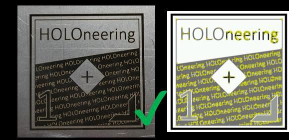
12th European LS-DYNA Conference 2019, Koblenz, Germany
The second step includes the representation of the simulations results as a defined color on the
object. For the result data, the maxima and minima are identified and afterward the values are
categorized into different classes. In order to ensure a correct assignment of the data, every facet of
the mesh is categorized with an individual number. The interface runs with the Java 11 runtime
environment and is a cloud solution. Consequently, it is completely independent of the operating
system. The main challenge in the visualization of simulation results is the user and often company
specific color and template definitions. Unfortunately, in a dynin-file, no information about the color
template and the user-specific settings of the visualization is saved. Moreover, in many cases, the raw
data has to be processed to more complex evaluations like a forming limit diagram plot. Therefore, in
the above-described procedure, an abstract color definition is used. Afterward, the abstract color
definitions are linked with a real color definition according to the individual and often tailored
requirements of the user. For the display, 8 different color scales were derived, which are finally
assigned to the final file as a texture file (Figure 2). The predefined textures correspond in this context
to a template with the dimensions 434 x 27 pixels. This clustering has the advantage that the texture
template can be stored very space-saving. The stored color textures thereby only have a size of 636
bytes.
Figure 2: Pre-designed color textures
Typically, an .dynain-file contains no information about the legend color as well as the value range of
the legend. The legend is generated individually in the post-processing of the file e.g. with LsPrePost.
Therefore, in analogy to the color definition, also the legend has to be designed manually for the
augmented reality in order to ensure an orientation and an assignment of the information. Within the
scientific investigations, it was found out, that in particular a perspective-dependent legend is required
in order to enable a good interaction with the simulations results and to improve the orientation of the
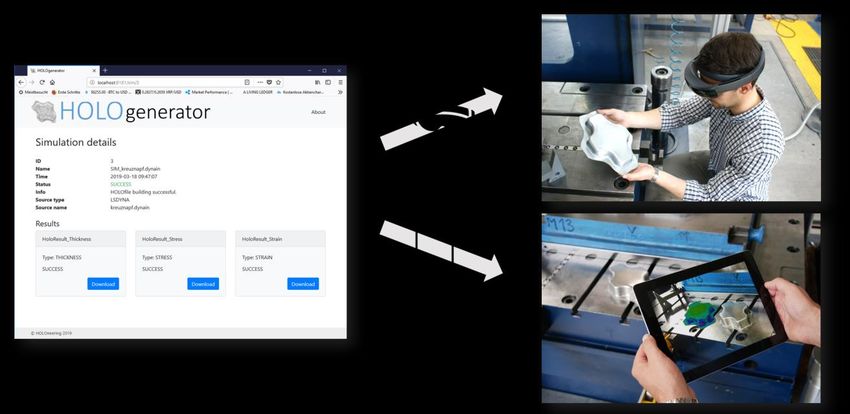
component. The integration of the legend is different for both operating systems. For the HoloLens an
object collider was developed, which is positioned beside the simulations parts and which allows an
automatic orientation according to the viewpoint of the user. The advanced mathematical model is
described in [11]. All information are thereby safed in the so-called holof-file, which can be directly
exported to the HoloLens via an FTP Server (Figure 3).
Figure 3: Dynamic export of Augmented Reality files for HoloLens and iPhone / iPad
© 2019 Copyright by DYNAmore GmbH
12th European LS-DYNA Conference 2019, Koblenz, Germany

For the visualization with iPhone and iPad the procedure is much more complicated, because based
on the requirements of Apple, the legend has to be directly integrated into the object file. For the
calculation of the position, the dimensions of the part are analyzed by the identification of the minimum
and maximum values of the x and y coordinates. Afterward, the mean value is calculated and the
legend is positioned on the middle axis. Typically, the visualization is completely static, which would
hinder a user-specific visualization. Moreover, a disadvantage arises, when the objects are rotated on
the smartphone because scripture is then mirrored. Within the research project, a solution was found
by a so-called normal orientated display of colors. Whereas all elements of the object are provided
with a double-sided display, the legend has only a one-sided display and therefore the mirroring effect
can be avoided.

In summary, the described procedure differs significantly from conventional Augmented Reality
solutions. Most AR apps available today are so-called static applications. This means that a defined
and completed app is developed, in which pre-information is loaded. This type of development is
relatively easy and corresponds to the state of the art. However, a dynamic reloading of new content
during runtime is not possible with this approach. In contrast, within the comprehensive scientific
investigations, a methodology was developed, which allows a transformation and visualization of new
content during runtime. Therefore, no new app has to be developed for new simulations results

4 Augmented Reality of simulation results with iPhone and iPad

With iOS, the company Apple has provided a very extensive opportunity to display 3D data in the year
2018. The development took place in this context with the company Pixar, which has gained great
prominence mainly through its animated films. The developments of Pixar have contributed to provide
a comprehensive but at the same time very sophisticated 3D engine, which in particular allows fast
processing of 3D-data on smartphones and tablets. In order to realize this fast processing, the data
(geometry and color) is stored in a binary file. This means that the format cannot be used for reverse
engineering. One of the biggest advantages in this context is the deep-rootedness of the visualization
and Augmented Reality features in iOS. For the user, this means that no extra software or app needs
to be installed on the iPhone or iPad. Therefore, the calculated files with above presented procedure
can directly be used on every iPhone and iPad running on iOS 12. iPhone and iPad can thereby be
used as a viewer for LsDyna simulation results (figure 4) without the need of an additional app.

Figure 4: Storage and visualization of forming results directly with iPhone / iPad without an additional app

Within the context of the holistic scientific investigations, the easy access to the simulations results
was analyzed. In particular, for the final application in the press shop, an online cloud based as well as
offline access to the data is an important requirement. The processing of the simulation results for iOS
has the great advantage that the data can be saved directly on the device. The B-pillar shown in the
figure 4 only has a size of 7.8 MB after conversion. This means that over 10,000 simulation results
could be stored on an average smartphone (iOS 12, 128 GB of memory). The files are thereby stored
in the folder "files" on the iPhone or iPad. Another alternative is to access via an enterprise cloud or
the iCloud of the company Apple. Moreover, based on the small size of the files, they can also be
send via Mail or even with messager like iMessage or WhatsApp.

                               © 2019 Copyright by DYNAmore GmbH
12th European LS-DYNA Conference 2019, Koblenz, Germany

5 Augmented Reality of simulation results with HoloLens

In contrast to the visualization with iPad and iPhone for the HoloLens until now no standardized AR file
format exits. The HoloLens belongs to the so-called Augmented Reality glasses. In contrast to a virtual
reality device, the user can still see his complete environment with the HoloLens and therefore the
system is much more convenient. However, the development of augmented reality applications is
much more challenging than a virtual reality application. The HoloLens software is based on Windows
10 Pro. For the development of a simulation specific app, the unity platform was used. Thereby, the
mixed reality environment from Microsoft can be used to enhance the real world with virtual objects.
Unfortunately, in contrast to iOS, for the HoloLens at the moment no standardized Augmented Reality
format exists, which can be used for the visualization of forming results. Within the scientific
investigations, a special format definition was developed in order to combine fast processing of the
data as well as to visualize the legend user orientated. The procedure is explained in detail in [11].
Within this comprehensive scientific investigations, in addition to visualisation, the Augmented Reality
approach was enlarged to measure distances and height differences between two points in an object.
These points are defined by attaching removable markers on it. The Augmented Reality app detects
characteristic features on the markers and locates them in the 3D space. The accuracy and
performance of the approach have been tested in scenarios with various light conditions, diverse
marker designs and different distances.

The reduction of complexity and time in the preparation of the measurement are added values to this
innovative approach. Moreover, the app is built in portable devices. The device used to implement our
solution is Microsoft Hololens (first generation – dev-mode). They are built with a set of sensors that
are necessary for our application: an Inertial Measurement Unit (IMU), a depth camera, four
environment cameras, a HD video camera and an ambient light sensor. For measuring height
differences and Euclidean distances between concrete points of the object, image targets (markers)
are used. These markers are magnetic and can be attached to – and removed from - the object of
interest. They are later detected using the cameras of the Mixed Reality glasses. Image targets are
designed in order to contain as many characteristic features (shapes, vertices, details) as possible.
For this approach, two different markers have been used. They present a similar design style but with
a significant variance to enable differentiation between them. Vuforia [12] – an Augmented Reality
software – has been used in the presented approach to extract these features and recognize the
markers. In addition, another important characteristic is extended tracking since it allows to improve
the continuous recognition of the images once they have been detected. The positions of the markers
will be tracked even when their images are partially occluded. Key aspects of the markers are good
contrast between bright and dark regions and their features distribution [13]. Furthermore, the flatness
of the markers has a big impact on the accuracy of the measurement. Moreover, its performance has
been tested in different light conditions. Results show that efficiency is high for diverse conditions, low
light environments can lead to a decrease in its output. Thereby, the color of the images is not
significantly important. Markers with different size have also been tested. The output does not only
depend on the marker size but also the distance to the glasses worn by the user. Markers with a size
from 25x25 mm to 50x50 mm provide a good balance of recognition rate and usability. Once images
are recognized by the cameras built in the HoloLens, their position in the 3D real space can be
calculated – thanks to spatial mapping and the IMU. Thus markers do not need to be simultaneously
seen by the user wearing the glasses. Once they are recognized, their positions on the 3D space are
saved. This allows placing the markers in different sides of the object to be measured.

The marker used was created within the development of this application to enable a good detection by
the HoloLens. The properties of the marker regarding recognition are evaluated automatically by
Vuforia. Specific points of the marker which are detected are presented in Figure 4. The marker fully
complies with the requirements defined by Vuforia. For the positioning of holograms, a marker was
printed in the format 60 mm x 60 mm. Subsequently, the marker can be detected within the user’s
environment. That allows a defined positioning of virtual data for applications that require a specific
alignment of the virtual models. In this way, numerical results can, for example, be positioned onto
physical parts for an evaluation of part properties. However, conventional markers are not suitable for
the rough environment of a press shop. Within the scientific investigations, the manufacturing and
quality of different marker types were investigated and compared. Thereby, makers out of sheet metal
showed the best results concerning wear and dust.

                               © 2019 Copyright by DYNAmore GmbH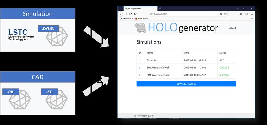
12th European LS-DYNA Conference 2019, Koblenz, Germany

Figure 4: Comparison of different marker types

Consequently, for the measurement task, the printed markers are replaced by markers, which are
applied directly onto sheet metal by laser marking. For the laser marking a TruMark Station 5000 of
the company, TRUMPF was used. Within this investigations, the structure and size of the markers
were kept constant. However, it was found out that the laser parameters and the resulting colour
distribution on the sheet metal have a strong influence on the detectability of the marker. As shown in
Figure 4 the markers can be engraved in black or white. However, the white engravement cannot be
detected by the HoloLens due to the weak contrast to the sheet. Therefore, the marker shown in
Figure 4 a) is used for distance measurement. The developed application detects the marker on the
sheet and calculates the distance to a second marker as soon as it is detected by the HoloLens. In the
case presented the distance between both markers is 195 mm, measured by a caliper gauge. The
distance calculated is shown in Table 1.

Figure 5: Experimental analysis of measurement quality with markers

The measurement using the HoloLens shows only minor
deviations to the reference measurement and is appropriate for
simple measurement tasks. A major advantage is the increased
efficiency as the measurement is done within a visual inspection,
making additional tools and physical execution of the
measurement task unnecessary. The application also works for a
combined approach, using on marker engraved on the sheet and
another flexible marker, for example, printed on a magnet.
Considering different fields of application this further increases
the flexibility of the developed solution.
                                                                         Table 1 Measurement results

                              © 2019 Copyright by DYNAmore GmbH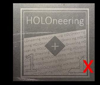
12th European LS-DYNA Conference 2019, Koblenz, Germany

6 Comparison of HoloLens and iPad

In the above section, the use of the HoloLens and iPhone for the visualization of simulation results
with Augmented Reality devises was presented. In summary, both systems allows a completely new
interaction with simulation results directly in the real world. With both systems the HoloLens and the
iPhone a dynamic loading of new content is possible. Consequently, the user can generate its own
content for the augmented reality. Moreover, the simulations can be positioned easily in the real world
without the necessity of markers. Finally, with HoloLens and iPad a scaling and turning of the objects
are possible. Thereby, a user-orientated legend is integrated. With the HoloLens in addition
measurement tasks can be integrated. However, there are also some drawbacks. In particular, the
high price and the high weight of the HoloLens limit its application. In addition, the small view angle
has to be kept in mind. The solution with the iPad is restricted concerning the measurement possibility.
A complete comparison of both systems is given in Table 2.

              HoloLens (Microsoft)                                  iPhone / iPad (Apple)

                                               Features

  Dynamic reloading of new objects on runtime            Dynamic reloading of new items on runtime
    Any positioning in the room (no markers             Any positioning on flat surfaces (no markers
                    required)                                             required)
             User-orientated legend                                User-orientated legend
                Turning of objects                                    Turning of objects
                Scaling of objects                                    Scaling of objects
                 Followed legend                                     Two Finger control
                 Gesture control                                          Low prize
       Measuring tasks (distance + angle)

                                              Challenges

                   High weight                                     Lower optical resolution

                    High price                               Limited measurement possibilities

                Limited view angle

Table 2 Comparison of HoloLens and iPhone for the augmented reality visualization of simulation
results

7 Summary and Outlook
Augmented reality offers great possibilities in order to visualize simulation results directly at the real
parts. In contrast to virtual reality, which is primarily used in gaming or consumer applications, the

                                 © 2019 Copyright by DYNAmore GmbH
12th European LS-DYNA Conference 2019, Koblenz, Germany
environment can be viewed directly with the help of augmented reality. The added value for the
application is thereby much larger, at the same side a technological solution is substantially more
demanding. In this context, two different systems have repeatedly proven their worth in the industrial
environment. On the one hand the HoloLens of the company Microsoft, on the other hand, the iPad
and iPhone of the company Apple. However, until now it was not possible to visualize simulations
results with augmented reality because of the high complexity of the data. Within the scientific
investigations, a methodology was developed in order to convert simulation results for the augmented
reality. After the conversion, the simulation results can be viewed instantly with any iPhone and iPad.
No additional software needs to be installed on the device. Both systems can, therefore, be used as a
viewer for simulation results. With the HoloLens the possibilities of augmented reality can be even
enhanced by direct interaction with the objects. In the presented work, the AR-glasses were used to
measure distances on the real part. Within this context, metal markers were developed, which can be
placed on the real parts.
Within further scientific investigations, the methodology will be improved extensively. Thereby, in
particular, new visualization templates will be investigated. For example, a forming limit diagram plot is
of high interest for the use in the press shop. Concerning the HoloLens, Microsoft just launched the
next generation of the HoloLens with an enhanced display and an improved mapping of the real word.
The investigations and the above-presented algorithm will be tested with new hardware in order to
qualify the improved measurement possibilities. Within this context, automatic object identification will
be analyzed. Moreover, a direct measurement of the complete real part will be integrated in order to
compare the simulations results directly with the real part without the use of additional measurement
equipment.
8 Literature
[1] Venkatesh, V., Thong, J. Y., & Xu, X. (2016). Unified theory of acceptance and use of
technology: A synthesis and the road ahead. Journal of the Association for Information
Systems, 17(5), 328-376.
[2] Pettersen, T.; Pretlove, J.; Skourup, C.; Engedal, T.; Lokstad, T.: Augmented Reality for
Programming Industrial Robots. In: ISMAR '03 Proceedings of the 2nd IEEE/ACM
International Symposium on Mixed and Augmented Reality, 2003, pp. 319-320
[3] Gaschler, A.; Springer, M.; Rickert, M.; Knoll, A.: Intuitive robot tasks with augmented reality
and virtual obstacles. In: IEEE International Conference on Robotics and Automation (ICRA),
2014
[4] Pai, Y. S.; Yap, H. J.; Singh, R.: Augmented reality–based programming, planning and
simulation of a robotic work cell. In: Proceedings of the Institution of Mechanical Engineers
Part B Journal of Engineering Manufacture 229 (6), 2014
[5] Fang, H.; Ong, S. K.; Nee, A. Y. C.: Robot Path and End-Effector Orientation Planning Using
Augmented Reality. 2012
[6] Fang, H. C.; Ong, S. K.; Nee, A. Y. C.: Robot Programming using Augmented Reality. In:
International Conference on CyberWorlds, 2009, pp. 13-20
[7] Marin, R.; Sanz, P. J.; Salvador Sánchez, J.: A very high level interface to teleoperate a robot
via Web including augmented reality. In: IEEE International Conference on Robotics and
Automation 3, 2002, pp. 2725-2730
[8] Jara, C. A.; Candelas Herias, F. A.; Fernández, M.; Medina, F. T.: An augmented reality
interface for training robotics through the web. 2014,
[9] https://www.wired.com/insights/2014/11/the-rise-of-apple-in-the-enterprise/
[10] https://docs.microsoft.com/en-us/windows/mixed-reality/hololens-hardware-details
[11] Lechner, M.; Schulte, R.; Meckler, S.; Merklein, M.: Augmented Reality Technology for the
Purpose of Sheet Metal Forming Simulation Evaluation. In: van den Boogaard, T. (Edtr.): 10th
Forming Technology Forum 2017 - Model Based Control for Smart Forming Processes,
Enschede, 2017, pp. 71-74
[12] https://www.vuforia.com/
[13] https://library.vuforia.com/articles/Solution/Optimizing-Target-Detection-and-Tracking-Stability
© 2019 Copyright by DYNAmore GmbHYou can also read