Dynamics of lubricated spiral bevel gears under different contact paths
←
→
Page content transcription
If your browser does not render page correctly, please read the page content below

Friction 10(2): 247–267 (2022)                                                                                  ISSN 2223-7690
https://doi.org/10.1007/s40544-020-0477-x                                                                       CN 10-1237/TH
RESEARCH ARTICLE

Dynamics of lubricated spiral bevel gears under different
contact paths
Wei CAO1,2, Tao HE3, Wei PU4,*, Ke XIAO5
1
    School of Construction Machinery, Chang'an University, Xi’an 710064, China
2
    Shantui Construction Machinery Co., Ltd., Jining 272073, China
3
    Department of Mechanical Engineering, Northwestern University, Evanston, IL60208, USA
4
    School of Aeronautics and Astronautics, Sichuan University, Chengdu 610065, China
5
    College of Mechanical Engineering, Chongqing University, Chongqing 400044, China
Received: 25 July 2020 / Revised: 09 October 2020 / Accepted: 23 November 2020
© The author(s) 2020.

Abstract: To assess the meshing quality of spiral bevel gears, the static meshing characteristics are usually checked
under different contact paths to simulate the deviation in the footprint from the design point to the heel or toe of the
gear flank caused by the assembly error of two gear axes. However, the effect of the contact path on gear dynamics
under lubricated conditions has not been reported. In addition, most studies regarding spiral bevel gears disregard the
lubricated condition because of the complicated solutions of mixed elastohydrodynamic lubrication (EHL). Hence,
an analytical friction model with a highly efficient solution, whose friction coefficient and film thickness predictions
agree well with the results from a well-validated mixed EHL model for spiral bevel gears, is established in the
present study to facilitate the study of the dynamics of lubricated spiral bevel gears. The obtained results reveal the
significant effect of the contact path on the dynamic response and meshing efficiency of gear systems. Finally, a
comparison of the numerical transmission efficiency under different contact paths with experimental measurements
indicates good agreement.

Keywords: spiral bevel gears; contact path; dynamic response; friction; meshing efficiency

1      Introduction                                                   operations. Hence, the contact path is typically moved
                                                                      to the heel and toe of the gear flank to verify the
Dynamics, which interrelates noise, durability, and                   static contact quality [1]. However, unlike spur gears,
vibration problems, is believed to be an important                    the contact geometry, kinematics, and mesh stiffness,
indicator in gear design owing to the mutual effect                   believed to be important excitations for gear dynamics
of dynamics, tribology, and fatigue problems. Mesh                    [2], are sensitive to the contact paths owing to the
forces may increase significantly under dynamic                       complicated spatial surface of gear flanks in spiral
conditions, and they are transmitted through the shaft                gears. Consequently, investigations into the effect of
and bearing into the gear housing, resulting in excessive             contact path on the dynamics and meshing efficiency
structure vibration. Moreover, the fatigue life of the                of spiral bevel gears can provide a full assessment of
two interaction surfaces is significantly affected by                 their transmission quality.
the fluctuating load generated by vibration. Owing                       The dynamics of gears has been extensively
to mounting errors or deformations of the bearing                     investigated previously, particularly for parallel axis
supporting system, the tooth surface contact area will                transmission, which focuses on various effect factors,
differ from the designed contact path during actual                   such as time-variant parameters [2, 3], lubrication [4, 5],

* Corresponding author: Wei PU, E-mail: Pwei@scu.edu.cn
248 Friction 10(2): 247–267 (2022)
Nomenclature
V , J , H Assembling parameters d (t ) Dynamic transmission error (DTE)
Lgr , Rgr Axial and radial projections of initial Rp , Rg Contact radii of pinion and gear,
point of gear respectively
p p , pg Unit vectors along pinion and gear Fm (t ) Dynamic mesh force
axes, respectively Fba , Fbr Axial and radial bearing loads,
jp , jg Unit vectors normal to pp and pg , respectively
respectively Z Number of tapered rollers
tp , tg Unit tangential vectors of pinion and l Half-loaded area angle of bearing
gear, respectively 1 Bearing contact angle
R bp , R bg Position vectors of pinion and gear, kn Stiffness due to assembly of inner ring-
respectively outer ring roller elements
n p , ng Unit normal vectors of pinion and gear, max Maximum bearing deflection in direction
respectively of resultant force vector
a minor , bmajor Unit vectors along minor and major M , K , C , F Mass, stiffness, damping, and force
axes of contact ellipse, respectively matrices, respectively
Rzx , Rzy Curvature radii along a minor and bmajor , I p , Ig Rotational inertia of pinion and gear
respectively about its axis, respectively
Shaft angle (angle between pp and pg ) mp , mg Masses of pinion and gear, respectively
p , g Rotational angles of pinion and gear, Tp , Tg Torques acting on pinion and gear,
respectively respectively
M p(g)
p
, p Rotational matrix of pinion with angle Tpf , Tgf Friction torques of pinion and gear,
respectively
p about p(g)
p
f Friction force
M pg , g Rotational matrix of pinion with fv , fb Viscous shear friction and boundary
angle g about pg friction, respectively
L Limiting shear stress of lubricant
R d Distance vector
Friction coefficient of dry contact
M( ) j Transformation matrix
Wa Load shared by asperities
tp , tg Angular increments of cutter for pinion Aa Asperity contact area
and gear machining, respectively (G G G ) Roughness parameter
qp , qg Cradle rotations for pinion and gear
( G / G ) Average asperity slope
machining, respectively
hc Film thickness
U e , Vs Entraining and sliding velocity vectors,
respectively
Composite root mean square roughness
hc
k m (t ) Mesh stiffness Film thickness ratio
c m (t ) Mesh damping
E Equivalent elastic modulus,
b Gear backlash
1 1 1 1 1 2
2 2
e m (t ) Kinematic transmission error
ph Maximum Hertzian pressure E 2 E1 E2
t Time 1 , 2 Poisson’s ratio of bodies 1 and 2
xi ( i p , g ) Displacement component Viscosity–pressure coefficient
p , g Pinion and gear rotational angles during Equivalent viscosity of lubricating oil
meshing, respectively G Limiting elastic shear modulus
| https://mc03.manuscriptcentral.com/friction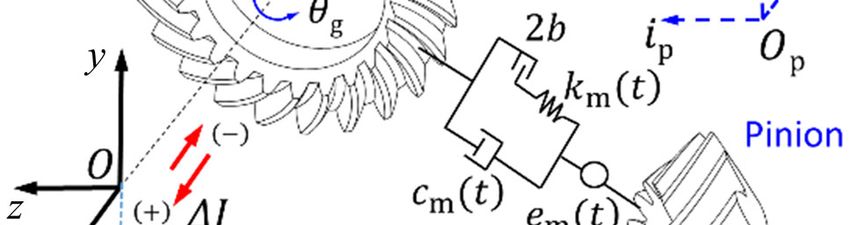
Friction 10(2): 247–267 (2022) 249
Shear stress k k-th meshing gear pair
p Pressure e Meshing efficiency
Tc Temperature Fro Rolling friction force
e Lubricant flow entrainment angle CT Thermal reduction factor
R pf , R gf Moment arms of pinion and gear, SRR Slide-to-roll ratio, SRR U e Vs
respectively Temperature–viscosity coefficient
Tpf , Tgf Total frictional torques of pinion and gear, Kf Heat conduction coefficient
respectively Average viscous shear stress
Friction coefficient Shear rate of lubricant
multi-degree of freedom (DOF) [6, 7], tooth profiles [8], and bearing stiffnesses. The shafts and their flexibilities
and assembling errors [9]. Although numerous studies were numerically simulated using Timoshenko beam
regarding gear dynamics have been published, studies finite elements, but the mesh line-of-action and
regarding the dynamics of spiral bevel gears are position were equivalently treated as invariant. Alves
limited owing to the complicated meshing geometry et al. [23] proposed a static and dynamic model
and kinematics. Donley et al. [10] proposed a dynamic for spiral bevel gears to investigate the tooth flank
hypoid gear model, in which the line-of-action and contact pressure under dynamic and static con-
mesh position were assumed to be invariant. Further- ditions. Friction was omitted in the abovementioned
more, nonlinear dynamic behaviors of spiral bevel studies [22, 23].
and hypoid gears have been simulated [11, 12], where As mentioned above, most studies focused on the
time-variant parameters were involved. Based on the effect of nonlinear time-varying mesh parameters,
proposed dynamic model, the effects of the drive and backlash nonlinearity, load, etc. on dynamic responses,
coast sides (asymmetry of mesh stiffness nonlinearity) whereas lubricated conditions were disregarded. Only
on spiral bevel and hypoid gear dynamics were a few reports regarding the effect of assembly errors
investigated [13]. In Refs. [11–13], a torsional dynamic on elastohydrodynamic lubrication [24] and the effect
model (two-DOF) was reduced to a one-DOF model of contact path on contact fatigue [25] under static
that disregarded the bearing support and gear flank conditions in spiral bevels have been published. The
friction. Furthermore, multi-DOF models of bevel conclusions indicated that the contact path affects the
and hypoid gear systems have been proposed [14, 15], lubrication characteristics and fatigue life significantly.
and the dynamic responses to the bearing stiffness However, the effects of the contact path on the
and torque load were investigated. To obtain more dynamics and efficiency of a lubricated spiral bevel
detailed dynamic characteristics for each meshing gear have not been reported. Therefore, the investi-
pair, a multipoint hypoid gear mesh model based gation into the effect of the contact path on dynamics
on tooth contact analysis (TCA) was established in will benefit future studies pertaining to lubrication
Ref. [16]. The aforementioned dynamic models were and fatigue life under nonlinear dynamic conditions.
assumed to be dry instead of the lubricated condition Hence, an eight-DOF dynamic model was developed
of the meshing tooth pair. The dynamics of lubricated in the present study based on a TCA model and an
spiral bevel gears were analyzed [17] based on a analytical friction model to simulate the nonlinear
torsional dynamic model, and the results were com- dynamics and meshing efficiency of spiral bevel
pared with those from a one-DOF model developed gears under different meshing paths. The analytical
by Ref. [11]. Mohammadpour et al. [18–21] proposed a friction model was demonstrated to be reasonable by
multiphysics tribo-dynamic model considering mixed comparing the present friction model with a previously
lubrication and bearing supports to investigate the published mixed elastohydrodynamic lubrication (EHL)
transmission efficiency and other dynamic behaviors. model of spiral bevel gears. Finally, the meshing
Yavuz et al. [22] investigated the dynamic mesh force efficiency was calculated and compared with the
in the frequency domain under different backlash numerical results.
www.Springer.com/journal/40544 | Friction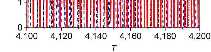
250 Friction 10(2): 247–267 (2022)
2 Methodology of spiral bevel gears. Hence, the determination of the
contact path is provided briefly below for clarity.
2.1 Assembling parameters for different contact To obtain the different contact paths, the gear and
paths pinion were first assembled at the designed point
(Fig. 1) using the assembling parameters [27, 28],
The aim of this study is to reveal the effect of contact
which included the pinion axial, vertical offset, and
path on dynamic responses; a schematic illustration
gear axial adjustment, denoted as ΔH, ΔV, and ΔJ,
of the contact path is shown in Fig. 1. Unlike involute
respectively. The initial point was determined by the
spur gears, the contact path and surface parameters
axial and radial projections Lgr and Rgr , respectively.
of spiral bevel gears are difficult to obtain analytically.
Subsequently, the mesh parameters for the different
Therefore, before modeling the dynamics of spiral
contact paths were computed using the TCA model.
bevel gears, a TCA model is required to determine
Figure 2 shows the contact relationship between the
the contact path and relevant contact parameters,
pinion and gear, in which O and O are the intersection
such as the principal directions, principal curvatures,
contact radii, entraining and sliding vectors, contact points between the pinion axis pp and gear axis pg (unit
load, and static transmission error at transient meshing vector) before and after the adjustment, respectively,
positions. The TCA model was programmed as a com- whereas points Op and Og denote the predesigned
puter package using Formula Translation (FORTRAN), crossing points of the two axes. As shown in Fig. 2,
and the methodology has been described in Refs. [26, two local coordinate systems SOp (Op , ip , jp , kp ) and
27]. The derivations of tooth contact parameters are SOg (Og , ig , jg , kg ) connected with the pinion and gear
laborious; therefore, this study focuses on the effect of axis are defined to compute the surface parameters
contact path on the dynamics and meshing efficiency and assembling parameters. It is noteworthy that ip
and ig are along pp and pg , and the direction of jp
coincides with jg . The vectors in system SOp are
expressed in system SOg to describe the vector operation.
Subsequently, the re-expressed vectors in system SOg
are as follows:
R
T T
(g)
bp , p(g) (g) (g)
p , np , t p M j R bp , pp , n p , t p (1)
where R bi , n i , and t i (i = p, g) are the position vector,
unit normal vector, and surface unit tangential vector
at a transient meshing position, respectively. is
Fig. 1 Schematic illustration of contact paths and initial contact the two-axis angle (shaft angle) between pp and pg ,
point. and M( ) j denotes the transformation matrix from
Fig. 2 Contact and assembling relationship between pinion and gear.
| https://mc03.manuscriptcentral.com/friction
Friction 10(2): 247–267 (2022) 251
system SOp to system SOg . If the two points on the under different contact paths in a mesh cycle. In fact,
pinion and gear flank are conjugated, then the the contact parameters are dependent on the machining
directions of the two surface normal vectors n(g)
p
and settings during the machining process, particularly the
ng coincide with each other, namely relative kinematics between the cutter and gear blank
[26]. Relevant descriptions of the contact geometries
ng n(g)
p
(2) and surface parameters are available in a previous
study [25].
It is assumed that Eq. (2) is satisfied when normal
vectors n(g)
p
and ng rotate about p(g) p
and pg with 2.2 Dynamic model
angle p and g [28], respectively.
The geared system adopted in the present study
In addition, the vectors in system SOg will be updated
comprised a spiral bevel gear pair and tapered roller
owing to the rotation angles of the pinion and gear,
bearings, as illustrated in Fig. 3. If the flexibility of
which are expressed as
the shaft is considered, then a finite element method
R (FEM) can generally be used to model the gear shafts
T T
( )
bp , n(p ) , t (p ) p , p
M p(g) R (g) (g) (g)
bp , n p , t p (3)
[22]. It is well known that the FEM is time consuming.
R R In fact, the bending effect of a shaft on the system
T T
( )
bg , n(g ) , t (g ) M pg , g bg , ng , t g (4)
dynamics is limited, as indicated experimentally (Fujii
where M p(g)
p
, p is the rotational transform matrix et al. [29]) and theoretically (Gosselin [30]) for a similar
dynamic system. Hence, the deformation of the shaft
of the pinion with respect to vector p(g)
p
with angle was not considered in the present study. A three-
p ; similarly, M pg , g represents the rotational dimensional (3D) dynamic model under different
contact paths in the spiral bevel gears is illustrated in
transform matrix of the gear.
Fig. 4. The transmission model of the pinion and gear
Furthermore, the conjugated points must satisfy
was discretized in terms of the time-varying mesh
the conjugation theory of a space curved surface as
stiffness km (t ) , mesh damping cm (t ) , gear backlash
follows [27]:
2b, and kinematic transmission error em (t ) along the
line-of-action direction. As shown in Fig. 4, the
n(g ) n(p ) , n(g ) Vs n(p ) Vs = 0 (5)
translational displacements, which can be defined
where Vs is the relative sliding velocity of two as x i ( xi , yi , zi , i ) , were considered; furthermore,
conjugated surfaces. the subscript i p , g refers to the pinion and gear,
respectively. It is noteworthy that the dynamic
When the initial running position (designed point)
model is described in the global coordinate system
is determined, the mating gear and pinion are
SO (O , x , y , z) ; xi , yi , and zi are the displacement
assembled in the target position through adjustments
H , J , and V , as depicted in Fig. 1. The adjustments
can be computed as follows [25, 27]:
R d R(bg ) R (bp ) = H p(g)
p
V p(g)
p
pg J pg (6)
If H , J , and V are calculated, the pinion
and gear can be assembled at the expected contact
point based on the corresponding adjustment values.
Generally, H and V are sufficient for mating the
pinion and gear on the designed point, i.e., J can be
set as zero.
After the pinion and gear are assembled, the contact
parameters can be obtained using the TCA model [25] Fig. 3 Schematic illustration of spiral bevel gear train.
www.Springer.com/journal/40544 | Friction
252 Friction 10(2): 247–267 (2022)
In Eq. (10), km (t ) is the mesh stiffness that can be
calculated using the loaded tooth contact analysis
(LTCA) model. LTCA is typically developed based on
a finite element (FE) model or FE-based models [31, 32].
However, the FE model is extremely time consuming
[33]. In this study, an efficient LTCA model proposed
by Sheveleva et al. [34] was adopted, and detailed
explanations of this model are available in Ref. [34].
Displacements xi , yi , and zi ( i p , g ) are axial
and lateral motions that correspond to the deflections
of the supporting bearings. The tapered roller bearing
is shown in Fig. 5. The method for calculating the load
and stiffness calculation is mature [35]. For conciseness,
Fig. 4 Dynamic mesh model. only a brief introduction of the bearing load is presented
herein. The bearing loads caused by the axial and
components along the x-, y-, and z-directions, respec- radial displacements are expressed in the integral
tively; p and g are the pinion and gear rotational form as follows [35]:
angles during the meshing process, respectively.
Z l 1 cos
n
2π l
The dynamic transmission error (DTE) is defined as Fba kn max sin 1 1 d
n
2
d (t ) Rpp dt Rgg dt n(p ) xp , yp , zp Z l 1 cos
T n
2π l
Fbr kn max
n
cos 1 1 cos d
2
T
n(g ) xg , yg , zg e m (t ) (7) (12)
where Rp and Rg are the contact radii. Owing to the where n is a constant, i.e., n = 10/9 for a line contact;
change in the contact path, the contact radii are variant Z is the number of tapered rollers; kn is the nonlinear
and can be computed as follows: stiffness due to the assembly of the inner ring, outer
ring, and roller elements, and it is related to the material
Rp n(p ) p(g)
p
R (bp ) (8) properties and bearing geometry; max dx sin 1
dr cos 1 represents the maximum bearing deflection
Rg n(g ) p(g)
g
R (bg ) (9) in the direction of the resultant force vector; l is the
half-loaded area angle; 1 denotes the bearing contact
It is noteworthy that n ( xp , yp , yp )T and n ( xg , yg ,
angle. When the bearing load is attained, the bearing
yg )T denote nonlinear displacements along the
supporting stiffness is calculated.
line-of-action due to the lateral and axial motions
of the pinion and gear axis, respectively. Using the
backlash nonlinear, the dynamic mesh force Fm can
be expressed as
Fm (t ) km (t ) fn d (t ) cmd (t ) (10)
where the nonlinear displacement function fn d (t )
is expressed as
d (t ) b , d (t ) b
f n d (t ) 0, d (t ) b (11)
(t ) b , (t ) b
d d Fig. 5 Schematic illustration of tapered roller bearing.
| https://mc03.manuscriptcentral.com/friction
Friction 10(2): 247–267 (2022) 253
Methods to calculate the gear mesh and bearing
forces have been developed; therefore, the differential
C 1
C1 I pn C 2 I gn C 3 mp C 4 mp
n
equation governing the dynamics of the spiral bevel
C 5 mp C6 mg C7 mg C8 mg
gear system is expressed as
1
K 2 K1 I pn K 2 I gn K 3 mp K 4 mp
(t ) Cx (t ) Kx(t ) F(t )
Mx (13) n
where
K 5 mp K 6 mg K 7 mg K 8 mg
x ( p , g , xp , yp , zp , xg , yg , zg ) (14)
b
F 2 F1 I p b , F2 I g b , F3 mp , F4 mp ,
n
T
M diag( I p , I g , mp , mp , mp , mg , mg , mg ) (15)
F5 mp , F6 mg , F7 mg , F8 mg
T
where I p and I g denote the rotational inertia of the X(t ) p , g , Xp , Xp , Zp , Xg , Yg , Zg (18)
pinion and gear about its axis, respectively; mp and
In Eq. (18), Ci , K i , and Fi (i = 1, 8) are the
mg are the masses of the pinion and gear, respectively.
corresponding elements in matrices C , K , and F ,
The stiffness matrix K includes the mesh stiffness and
respectively. Subsequently, Eq. (17) can be solved
bearing stiffness. The damping matrix C is expressed
using the Runge–Kutta method.
as C 2 mK , where is the damping ratio,
which can be obtained from Refs. [17, 18]. F is the 2.3 Gear friction model
force vector that includes external excitations and
internal forces. The external excitation force is the The excitation in the torsional direction comprises
torque fluctuation, and the internal excitation force is the applied torques Tp and Tg as well as the friction
a result of the time-varying spatial vector, transmission torques Tpf and Tgf of the pinion and gear owing to
error, backlash, and friction torque [17]. gear flank friction, respectively. When the film in the
Matrices K and C , and vector F will not be conjugated gear flank is thin, mixed lubrication occurs,
expanded comprehensively herein for brevity, as they and the mesh load is supported by asperity contact
have been derived previously [36]. It is noteworthy and a film simultaneously. The authors have previously
that R p R g 0 was assumed in Refs. [18, 21]; investigated the friction characteristics of spiral bevel
subsequently, the dynamic model was reduced as a gears under different contact paths [25] using a
seven-DOF system. However, the rate of change of gear mixed EHL model that can accommodate 3D surface
teeth contact radii may result in more complicated roughness. However, the computations of the governing
dynamic responses, such as severe tooth separations, equation of the mixed EHL model are time consuming.
particularly at higher speeds [17]. Hence, the rate To reduce the solving burden, the friction coefficient
of change of the contact radii was considered in the was predicted using an analytical method, and it will
present study. To improve the computational efficiency be compared to the results from the mixed EHL model
when using Eq. (13), the normalization was performed [25] in later discussions to demonstrate the feasibility
in this study as follows: of the proposed analytical friction model.
A mixed lubrication condition was considered. The
Xi xi b , Yi yi b , Zi zi b , i p , g ; T n t friction force f action on the gear flank comprised
(16) viscous shear friction fv and boundary friction f b ,
expressed as follows:
where n is the reference frequency, which is often
selected as the resonant frequency. Based on Eq. (16), f fv fb (19)
the equation of motion is rewritten as
To calculate the boundary friction f b , a Gaussian
(t ) KX asperity contact model [18, 36] was used in the present
X (t ) CX (t ) F (t ) (17)
study. The boundary friction force can be calculated
where using the boundary friction coefficient [25, 36]:
www.Springer.com/journal/40544 | Friction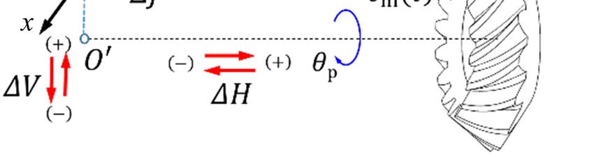
254 Friction 10(2): 247–267 (2022)
f b Wa (20) In the Eq. (26), E is the material modulus, is the
viscosity–pressure coefficient, and 0 is the viscosity
where denotes the coefficient of dry or boundary of the lubricant. Re and Rs are the effective curvature
contact, generally assumed to be constant [25, 36]. In radii, which are defined as
this case, was set to 0.13. According to Ref. [37], the
1 cos e sin e 1 cos e sin e
2 2 2 2
load shared by asperities Wa and the asperity contact
, (27)
area Aa can be expressed as Re Rzy Rzx Rs Rzx Rzy
16 2 G where e denotes the lubricant flow entrainment
Wa πA(G G G )2 EF2 5 ( ) (21)
15 G
angle; e arc cos U e a minor U e
a minor ; Rzx and
Aa π 2 A(G G G )2 F2 ( ) (22) Rzy are the curvature radii along the minor axis a minor
and major axis bmajor of the contact ellipse, respectively;
As suggested by Greenwood and Tripp [37], the
similarly, these parameters were obtained using the
roughness parameter (G G G ) should range from 0.03
TCA model. The direction of friction was determined
to 0.05, whereas the average asperity slope ( G G )
by the sliding vector Vs . Hence, the sliding velocity
should range from 0.0001 to 0.01. The statistical func-
vector Vs and the entraining vector U e are expressed
tions F2 5 ( ) and F2 ( ) are described as follows [37]:
as follows:
F2 5 ( ) = – 0.003585 + 0.04975 4 0.27498 3
Vs p ( pp R bp ) g ( pg R bg ) x p x g (28)
+ 0.7615 – 1.06924 + 0.61652
2
(23)
1
Ue ( p R bp ) g ( pg R bg ) x p x g (29)
F2 ( ) = 0.00195 5 + 0.029180 4 0.17501 3 2 p p
+ 0.52742 2 0.80423 + 0.500 (24)
For viscous stress , a viscoelastic non-Newtonian
hc fluid model (Bair and Winer [42]) can be used as
where is the film thickness ratio, is the
follows:
composite root mean square roughness, and hc is
L
the film thickness. The hc was calculated using an = ln 1 (30)
analytical film thickness formula for elliptical point G L
contacts considering the oblique entraining angle [38,
where the lubricant viscosity is assumed to be a
39], which was originally obtained under light load
function of pressure, and a typical relationship is
conditions [38]. However, Wang et al. [40] and Jalali-
e p [25], which has been justified to be suitable
Vahid et al. [41] discovered that the curve-fitting
experimentally by He et al. [43] for computing the
formula by Chittenden et al. [38] can yield reasonable
shear force in a wide range of loads. The limiting shear
predictions of the film thickness compared with
elastic modulus G and the limiting shear stress
numerical results under a heavy-load operating
L were calculated as a function of temperature and
environment with arbitrary entrainment. The curve-
contact pressure, expressed as follows [44]:
fitting formula is expressed as follows:
G ( p , Tc ) 1.2 p 2.52 0.024Tc 10 8
2
(31)
0.073 Rs 3
(25) L ( p , Tc ) 0.25G
hc 4.31ReU G W
0.68 0.49
1 exp 1.23
Re
The viscous shear stress in the contact zone is
related to the contact pressure. In the present study,
where the dimensional parameters are
contact pressure was discretized using a Hertzian
contact model [39], which has been demonstrated as a
πFm π0 U e 2
W , U , G E (26) reasonable assumption for spiral bevel gears [45].
2 ERe
2
4 ERe π
Once the central film thickness and sliding velocity
| https://mc03.manuscriptcentral.com/friction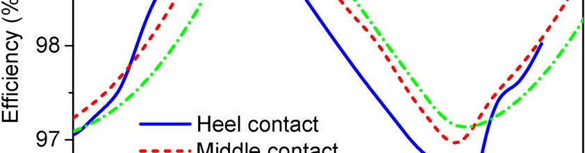
Friction 10(2): 247–267 (2022) 255
vector are provided, the shear rate of the lubricant at It is noteworthy that the rolling friction loss is con-
the center of the mesh can be computed. The shear rate sidered, and the rolling friction force Fro is calculated
can be expressed as a linear relationship, as widely as [46, 47]
used in Refs. [39, 44], which can be expressed as
0.658
C 4.318 Rx 0 U e cos( e )
0.0126
Fm
Vs Fro T (37)
Rzx ERzx
(32)
hc
The thermal reduction factor CT is defined as
Solving Eq. (30), the average viscous shear stress,
[45, 46]
, can be obtained by averaging the local shear in
the elliptical contact zone. Subsequently, the viscous 1 13.2 ph E L0.42
CT
s
friction is obtained as follows: (38)
1 0.213 1 2.23SRR0.83 L0.64
s
f v A Aa (33)
where SRR Vs U e represents the slide-to-roll
Before calculating the frictional torque, the moment ratio; ph is the maximum Hertzian contact pressure;
arms Rpf and Rgf applied to the pinion and gear must
2
Ls 0 U e Kf ; and Kf are the temperature–
be computed. The sign of friction is determined by the
direction of the sliding velocity. The friction torque viscosity and heat conduction coefficients of the
may assist or resist the motion of the pinion and gear. lubricant, respectively.
Hence, it is necessary to compute the moment
arms R pf and R gf while considering the sign of the 3 Results and discussion
relative sliding velocity, as follows:
3.1 Numerical result analysis
R bp
R pp Vs
The parameters of the spiral bevel gears and assembled
pf
Vs
(34) bearings are listed in Table 1. Additionally, three
R bg pg Vs different contact paths are depicted in Fig. 1. The
Rgf
Vs width of the gear flank is Bw , and design points 1, 2,
and 3 are located at the pitch cone; their coordinates
Subsequently, the total frictional torques Tpf and ( Lgr , Rgr ) are (40.01 mm, 117.43 mm), (36.54 mm,
Tgf are expressed as 107.25 mm), and (33.08 mm, 97.08 mm), respectively.
The contact paths through points 1, 2, and 3 are
N
Tpf Rpf Fm
(k) (k) (k) referred to as the heel, middle, and toe contacts. The
k 1 input torque acting on the pinion was set as 200 N·m.
N
(35)
T ( k ) R( k ) F ( k )
gf gf m
The flowchart of the methodology of the dynamics
k 1 of a spiral bevel gear under different contact paths
is summarized in Fig. 6. As shown in Fig. 6, the TCA
where k 1, , N is the k-th meshing gear pair that
analysis involves complicated numerical processes for
is determined using the TCA model. The friction
attaining the assembling and meshing parameters
coefficient ( k ) for each conjugated gear pair k is com-
under different contact paths.
puted using Eq. (19).
The three types of tooth contact trajectories are
Based on the friction model, the instantaneous
plotted in Fig. 7, and the corresponding assembling
efficiency of the spiral bevel gear can be estimated as
adjustments, obtained using the methods described
in Section 2.1, are listed in Table 2. Under different
N
1
e 1 (k)
Fm( k ) Vs( k ) 2 Fro( k ) U(ek ) 100% contact paths, the relevant parameters for the dynamic
k 1 T
p p model were calculated using the TCA model. Figure 8
(36) shows the variations in the meshing stiffness and
www.Springer.com/journal/40544 | Friction
256 Friction 10(2): 247–267 (2022)
Table 1 Gear pair and bearing parameters. the mesh stiffness km (t ) was relatively large for the
Gear parameter Pinion (mm) Gear (mm) heel contact, and the stiffness was affected by the
Number of teeth 15 44 contact ratio. The static transmission error em (t )
Module (mm) 5.8 depended on the microgeometry and manufacturing,
Tooth width (mm) 43 and it appeared as a sinusoidal-like form, as shown
Average pressure angle (°) 20 in Fig. 8. The transmission error was significant at the
Mean spiral angle (°) 30
toe contact. Figure 9 summarizes the pinion and gear
contact radii, Rp and Rg . The results show that the
Shaft angle (°) 90
variation in the contact radii was limited. Therefore,
Face angle (°) 22.17 72.83
the assumptions of constant contact radii and invariant
Pitch angle (°) 18.82 71.18
rate of change of the contact radii can be reasonable
Root angle (°) 17.17 67.84
at low speeds. Figure 10 shows the curvature radii
Outside diameter (mm) 100.08 257.08 along the minor and major axes of the contact ellipse,
Hand of spiral Left Right which are related to friction calculations. The frictional
Mass (kg) 1.40 6.20 moment arms of the pinion and gear are shown in
2 –3
Inertia (kg·m ) 1.23 × 10 6.23 × 10⁻² Fig. 11, and it is clear that the sign of the arms changed
Backlash (μm) 75 at design points 1, 2, and 3. To incorporate these
Tapered roller bearing time-variant parameters into a dynamic model, Fourier
13 series functions with respect to the pinion rotational
Number of tapered roller elements, Z
Bearing contact angle, 1 (°) 15
angle were applied in the present study to simulate
the periodical parameters [17] during the meshing of
Effective stiffness of inner
4 × 10⁸
ring-rolling-outer ring, kn (N·m–1) spiral bevel gears.
The gear materials, lubricant, and roughness
parameters for the present simulations were based on
those in Ref. [25]. Figure 12 presents the maximum
and minimum amplitudes of the DTE during different
speeds for the heel, middle, and toe contacts. During
the speed sweep, the critical resonance regions occurred
at approximately 10,400 rpm for the toe and middle
contacts and 11,000 rpm for the heel contact. In the
resonance region, the amplitudes of the DTE of the
middle and heel contacts fluctuated in a range larger
Fig. 7 Three contact paths and contact ellipses.
Fig. 6 Flowchart of methodology of dynamics and efficiency of Table 2 V and H values for different contact paths (mm).
spiral bevel gear.
Contact path Toe contact Middle contact Heel contact
static transmission error (kinematic error) from the V 1.084 0.0248 –1.943
meshing-in to the meshing-out point. It is clear that H –0.113 0.155 1.194
| https://mc03.manuscriptcentral.com/frictionFriction 10(2): 247–267 (2022) 257
Fig. 8 Mesh stiffness and kinematic error in mesh cycle for different contact paths.
Fig. 9 Contact radii of pinion and gear for mesh cycle.
Fig. 10 Curvature radii along minor and major axis of contact ellipse in mesh cycle.
Fig. 11 Frictional moment arm of pinion and gear during engaging cycle.
www.Springer.com/journal/40544 | Friction258 Friction 10(2): 247–267 (2022)
than that of the toe contact. Except for the resonance,
the toe contact exhibited a large DTE. A clear jump
phenomenon was observed, as was discovered in
Refs. [11, 18], particularly for middle and heel contacts.
The time histories of the dynamic transmission error
for the toe, middle, and heel contacts under the critical
resonance speed are plotted in Fig. 13, depicting that
the contact paths primarily affected the values of the
minimum DTE instead of the maximum DTE at the Fig. 14 Maximum and minimum mesh force amplitudes during
pinion speed sweep.
resonance regions.
The dynamic mesh force amplitudes at different
speeds are illustrated in Fig. 14. The responses of the
dynamic mesh force with respect to the pinion speed
were similar to the dynamic transmission error. In
the vicinity of resonance, the minimum force became
zero, indicating the occurrence of teeth separation,
resulting in contact loss. In addition, in the frequency
region, the heel contact occupied a wider speed range,
where separation occurred, compared with the case
of middle and toe contacts. The periods of responses
of the dynamic mesh force and its corresponding
Fig. 15 Time histories of dynamic mesh force at resonances.
maximum Hertzian contact pressure are summarized
in Figs. 15 and 16. As shown in Fig. 15, the dynamic
mesh force of the heel contact was the greatest,
Fig. 12 Maximum and minimum DTE amplitude during pinion Fig. 16 Time histories of maximum Hertzian pressure at
speed sweep. resonances.
whereas the force was the minimum for the toe
contact. However, as shown in Fig. 16, the maximum
Hertzian contact pressure ph was high for the toe
contact compared with those of the heel and middle
contacts, although the meshing force was relatively
low for the toe contact. This was because the surface
geometries were different under different contact paths,
as indicated in Fig. 10 by the curvature radii Rzx and
Rzy along the minor and major axes of the contact
ellipse, respectively. The maximum Hertzian pressures
Fig. 13 Time histories of DTE at resonant speed. for the toe, middle, and heel contacts at resonance
| https://mc03.manuscriptcentral.com/frictionFriction 10(2): 247–267 (2022) 259
were 3.84, 3.18, and 2.64 GPa, respectively. The addition, the tendency of the gear axial displacement
octahedral stress distributions were calculated under with respect to speed differed from that of the pinion,
the maximum Hertzian pressures. The Hertzian contact as shown in Fig. 19. Compared with the middle
pressure and octahedral stress contours are shown in and heel contacts, the axial displacement amplitude
Fig. 17. The maximum octahedral stresses were 1.76, of the toe contact fluctuated in a wide range, and
2.27, and 2.44 GPa under the heel, middle, and toe the maximum displacement was large. Analyses of
contacts, respectively. Despite the relatively small Figs. 12, 14, 18, and 19 show that the responses of
contact force for the toe contact, as shown in Fig. 15, the mesh force and DTE were similar to those of the
conspicuous surface stress concentrations were axial and radial displacements of the pinion. It can be
observed owing to intermittent asperity contacts, which concluded that the dynamic mesh force and dynamic
directly caused premature surface micropitting [48, 49]. transmission error under different contact paths were
The stress solution was obtained from a mixed EHL primarily affected by the pinion displacements. In
model and an octahedral stress equation, which have addition, the vibration of the gear was severe under
been described in our previous study [25]. For brevity, the toe contact path.
the formulae of the mixed EHL model and stress The lateral and axial displacements of the shaft
are omitted herein, and readers can refer to Ref. [25] resulted in structural excitations that transmitted
for details. Additionally, the higher Hertzian contact to the differential housing through bearings. A
pressure generated larger stress distributions and case study of bearings A nd C was performed, and
stress-affected volumes, which dominated the contact the variation in the transmitted force through the
fatigue life [25]. supporting bearings in the axial and lateral directions
The radial and axial displacements of the pinion are depicted in Figs. 20 and 21, respectively. For
and gear under different contact paths during a speed bearing A, the results were generally similar to the
sweep are shown in Figs. 18 and 19, respectively. For trends of the DTE and dynamic mesh force variation.
the pinion, the radial displacement was the resultant For bearing C, the axial and radial bearing forces under
displacement of xp and yp , and the axial displacement toe contact were extremely high at approximately
was zp . For the gear, yg and zg represent the radial 8,800 r/min, consistent with the variation in the gear
displacement, and xg represents the axial displacement. lateral displacement, as depicted in Fig. 18. Furthermore,
The radial and axial displacements of the pinion it was discovered that the bearing force under the
exhibited a trend similar to that of the dynamic toe contact was greater than those under the middle
transmission error. In a wide speed range, the amplitude and heel contacts apart from the resonance regions.
of the radial displacement response of the pinion was Additionally, it was observed that the axial bearing
greater than that of the gear. However, for the toe force was much lower than the lateral bearing force,
contact of the gear, a significant discontinuity in radial particularly in the resonance region.
displacement was discovered at 8,800 r/min, and the The meshing efficiency of spiral bevel gears is related
amplitude was approximately 100 μm, which was much to the friction power loss; therefore, an accurate friction
larger than the radial displacement of the pinion. In model is required for predicting the instantaneous
Fig. 17 Contact stress distributions under maximum Hertzian pressure for different contact paths.
www.Springer.com/journal/40544 | Friction260 Friction 10(2): 247–267 (2022)
Fig. 18 Response of radial displacement of pinion and gear under Fig. 20 Maximum and minimum radial and axial bearing forces
different contact paths. (bearing A) during pinion speed sweep.
Fig. 19 Response of axial displacement of pinion and gear under Fig. 21 Maximum and minimum lateral and axial bearing forces
different contact paths. (bearing C) during pinion speed sweep.
meshing efficiency. Only a few studies have focused U e , viscosity of lubricant 0 , contact geometry Rzx ,
on friction in spiral bevel or hypoid gears, such as and surface roughness , i.e., f (SRR , ph ,0 ,| Vs |,
those from Xu and Kahraman [46], Kolivand at al. [47], | U e |, Rzx , ) . To indicate the effect of the line-contact
and Paouris et al. [39]. An analytical method of the assumption on friction predictions, the results obtained
friction model was used in Refs. [18, 19, 39]; however, using the method from Xu and Kahraman [46] were
it has not been validated for the application of spiral compared to those obtained from the mixed EHL
bevel or hypoid gears. Xu et al. [46, 47] investigated model of spiral bevel gears [25]. The reliability of the
the efficiency of hypoid gears, whereas the contact mixed EHL model applied in spiral bevel gears was
was assumed to be a line contact. Xu and Kahraman validated in Ref. [50]. In addition, the predictions of
[46] proposed a fitting formula for the friction the present analytical friction model were compared
coefficient based on a significant amount of mixed with the results from the mixed EHL model. The
EHL (line-contact model) analyses; it was expressed friction coefficient predictions from different friction
as a function of the maximum Hertzian contact models under different contact paths are plotted in
pressure ph , slid-to-roll ratio SRR, entraining velocity Fig. 22. It is noteworthy that the applied rotational
| https://mc03.manuscriptcentral.com/frictionFriction 10(2): 247–267 (2022) 261
speed and torque of the pinion were 3,000 r/min and by the proposed model for the toe, middle, and heel
190 N·m, respectively. It was observed that the friction contacts is plotted in Fig. 24. The maximum efficiency
coefficient from the mixed EHL model [25] first was reached in the vicinity of the pitch cone where
increased and subsequently decreased, reaching the the sliding velocity was the minimum [25].
maximum at the pitch cone. Similar results have been Once the friction model was developed, the
reported in Refs. [51, 52], where a relatively realistic instantaneous meshing efficiency can be analyzed
lubrication model (the entrainment angle was con- using the tribo-dynamic model. Figure 25 shows the
sidered) of a spiral bevel gear was employed. The averaged meshing efficiency over a wide speed
friction coefficient of the toe contact was relatively
high compared with those of the middle and heel
contacts. As shown in Fig. 22, the friction model with
a line-contact assumption proposed by Xu and
Kahraman [46] indicated a relatively large prediction
error around the pitch cone owing to the negligence
of the entrainment angle. This indicates that the
simplification of the line contact was reasonable for
the friction analysis of spiral bevel gears apart from
the neighboring pitch cone. The friction coefficient of
the present analytical model was consistent with the
results of the mixed EHL model for the toe, middle, and Fig. 23 Variation in film thickness in mesh cycle under different
heel contacts. To further demonstrate the analytical contact paths.
model, the center film thickness was analyzed, as
shown in Fig. 23. It was clear that the film thickness
from the analytical model agreed well with the mixed
EHL predictions. The static meshing efficiency achieved
Fig. 24 Predictions of meshing efficiency during mesh cycle
under static condition.
Fig. 22 Variations in friction coefficient obtained from different Fig. 25 Dynamic meshing efficiency during pinion speed sweep.
models.
www.Springer.com/journal/40544 | Friction262 Friction 10(2): 247–267 (2022)
range. It was observed that the efficiency increased was relatively high for the heel contact [25] owing to
with the pinion speed when the pinion speed was less the large rotational radii, as illustrated in Fig. 9.
than 6,000 rpm. In the resonance regions, the efficiency
fluctuated significantly owing to the tooth separations, 3.2 Experimental results
thereby resulting in the disappearance of friction loss. The friction, which is related to the transmission
Furthermore, it was evident that the efficiency of the efficiency, was introduced to the dynamic model under
toe contact was higher than those of the middle and different contact paths. Hence, the transmission
heel contacts. Figure 26 shows the history of the efficiency was tested to verify the methodology used
meshing efficiency and the dynamic friction coefficient in the present study. Transmission efficiency tests were
in a mesh cycle for the case where the rotational speed performed using a gear transmission system test rig,
and torque of the pinion were 3,000 r/min and 190 N·m, as shown in Fig. 27, to validate the dynamic model
respectively. Compared with Fig. 24, the dynamic coupled with friction. The parameters of the tested
meshing efficiency was lower than the static efficiency, gear pair are shown in Table 3, and the parameters of
as expected, owing to the power loss in vibration of the assembled bearings in the test rig were the same
the shaft in the spiral bevel gears along the lateral and as those listed in Table 1. The assembly adjustments
axial directions. Although the difference in the friction for the toe, middle, and heel contacts, obtained using
coefficient was limited for different contact paths, the the methods described in Section 2.1, are listed in
minimum instantaneous efficiencies were 89.1%, 89.5%, Table 4. In the experiment, Mobil gear oil 600XP150
and 91.6% for the heel, middle, and toe contacts, was used as the lubricant. The parameters of the gear
respectively. This was because the sliding velocity materials, lubricant, and root mean square (RMS)
Fig. 26 History of (a) meshing efficiency and (b) dynamic friction coefficient in mesh cycle.
Fig. 27 Gear transmission system test rig and mounted gears.
| https://mc03.manuscriptcentral.com/frictionFriction 10(2): 247–267 (2022) 263
Table 3 Gear pair parameters. roughness are listed in Table 5, and the operating
Gear parameter Pinion (mm) Gear (mm) temperature was 30 °C. The transmission efficiency
Number of teeth 25 34 during the test was defined as e Tpp (Tg g ) , where
Module (mm) 5.0 the torque and angular speed were measured based
Tooth width (mm) 30 on the torque sensor and angular encoder at a sampling
Average pressure angle (°) 20 frequency of 1,000 Hz.
Mean spiral angle (°) 35 The maximum mechanical speed of the output
Shaft angle (°) 90 angular encoder (mounted on the driven side) and
Face angle (°) 39.63 56.00 input angular encoder (mounted on the driving side)
Pitch angle (°) 36.33 53.67 were 1,000 and 3,000 r/min, respectively. The maximum
Root angle (°) 34.00 20.37 input and output torques of the motor were 96 and
Outside diameter (mm) 105.50 105.50 236 N·m, respectively. It is noteworthy that the shaft
Hand of spiral Left Right speeds were measured using an angular encoder
Mass (kg) 1.64 3.81 integrated in a motor with a wide speed range of
Inertia (Kg·m2) 3.45 × 10⁻³ 1.36 × 10⁻²
0–6,000 r/min, and they were not affected by the
protective speed of the output angular encoder
Backlash (μm) 75
(1,000 r/min). In a smaller torque range, the effect of
Table 4 V and H value for different contact paths (mm). torque on efficiency was limited compared with that
of speed. Hence, the efficiency was tested in a pinion
Contact path Toe contact Middle contact Heel contact
speed range of 10–1,500 r/min with a load of 60 N·m
V 0.860 –1.491 –1.644
acting on the gear, and the results are summarized in
H –0.292 0.106 1.370
Fig. 28. As shown in Fig. 28(a), the measured efficiency
Table 5 Parameters of gear materials, lubricant, and roughness.
Effective elastic Density of lubricant Lubricant viscosity Viscosity–pressure RMS roughness
modulus (GPa) (kg/L) (mm2/s) coefficient (1/Pa) (μm)
150 (40 °C)
219.78 0.89 2.57 × 10⁻⁸ 0.5
14.7 (100 °C)
Fig. 28 Transmission efficiencies of (a) tested results and numerical results: (b) toe contact, (c) middle contact, and (d) heel contact.
www.Springer.com/journal/40544 | Friction264 Friction 10(2): 247–267 (2022)
increased with the speed, and the efficiency from large results from a mixed EHL model of spiral bevel gears
to small was that of the toe, middle, and heel contacts, proposed previously. In addition, the line contact
coinciding with the trend of the numerical results. In assumption for the conjugation of the spiral bevel
addition, the numerical predictions agreed well with gear appeared unreasonable owing to the significant
the tests at different speeds and contact paths; however, prediction error of the friction coefficient at the neighbor
the former appeared slightly larger than the latter. of the pitch cone.
This deviation may be a result of the subtraction error 4) The dynamic efficiency was lower than the quasi-
of the internal friction caused by the motor, bearing, static efficiency, as expected, owing to the energy loss
and shafting, particularly at 10 r/min. The deviations caused by the vibration of the gear shaft. At resonance,
between the experimental and numerical results were the efficiency fluctuated because of the tooth separations.
significant because of the effect of internal friction The contact radii of the toe contact were relatively
loss. small, and correspondingly, the sliding velocity was
relatively low, resulting in a high meshing efficiency
for the toe contact.
4 Conclusions
5) A comparison of the numerical transmission
The static meshing quality in spiral bevel gears is efficiencies under different contact paths with the
generally verified under different contact paths; experimental measurements indicated good agreement.
however, the dynamic characteristics under different The tested efficiency was slightly smaller than the
contact paths have not been reported. Hence, the predicted values owing to the effect of the internal
effects of contact paths on the dynamic response and friction loss.
meshing efficiency of a lubricated spiral bevel gear
pair were analyzed based on the combination of an Acknowledgements
eight-DOF dynamic model, a TCA model, and an
analytical friction model. The friction model was The present study was founded by the National
validated through a comparison between the present Natural Science Foundation of China (Grant Nos.
analytical results and the predictions of a mixed EHL 52005047 and 51875369), Natural Science Basic Research
model proposed previously in terms of the friction Plan in Shaanxi Province of China (Grant Nos.
coefficient and film thickness. Based on the presented 2020JQ-367 and 2020JQ-345), China Postdoctoral
results, the following conclusions were obtained: Science Foundation (Grant No. 2020M672129), and
1) The effects of contact paths on gear dynamics the Fundamental Research Funds for the Central
revealed a complicated nonlinear response in the Universities, CHD (Grant No. 300102250301).
vicinity of resonance, where the amplitudes of DTE
of the middle and heel contacts exhibited significant References
jump discontinuities. Except for resonance, the DTE
amplitudes, dynamic meshing force, and lateral [1] Goldfarb V, Barmina N. Theory and Practice of Gearing
and axial bearing forces of the toe contact fluctuated and Transmissions. Cham: Springer International Publishing,
significantly during a wide speed sweep. 2016.
[2] Kahraman A, Singh R. Interactions between time-varying
2) At resonance, the dynamic meshing force was
mesh stiffness and clearance non-linearities in a geared system.
small for the toe contact. However, the maximum
J Sound Vib 146(1): 135–156 (1991)
Hertzian contact pressure was higher than those of
[3] Shen Y J, Yang S P, Liu X D. Nonlinear dynamics of a spur
the middle and heel contacts owing to the effect of
gear pair with time-varying stiffness and backlash based on
contact geometry, causing high surface stress con- incremental harmonic balance method. Int J Mech Sci
centrations, which were closely related to surface 48(11): 1256–1263 (2006)
micropitting and contact fatigue. [4] Khabou M T, Bouchaala N, Chaari F, Fakhfakh T, Haddar M.
3) The friction coefficient and film thickness from Study of a spur gear dynamic behavior in transient regime.
the present analytical model agreed well with the Mech Syst Signal Process 25(8): 3089–3101 (2011)
| https://mc03.manuscriptcentral.com/frictionFriction 10(2): 247–267 (2022) 265
[5] Li S, Anisetti A. On the flash temperature of gear contacts Multiphysics investigations on the dynamics of differential
under the tribo-dynamic condition. Tribol Int 97: 6–13 hypoid gears. J Vib Acoust 136(4): 041007 (2014)
(2016). [19] Mohammadpour M, Theodossiades S, Rahnejat H, Kelly P.
[6] Özgüven H N. A non-linear mathematical model for dynamic Transmission efficiency and noise, vibration and harshness
analysis of spur gears including shaft and bearing dynamics. refinement of differential hypoid gear pairs. Proc Inst Mech
J Sound Vib 145(2): 239–260 (1991) Eng Part K: J Multi-body Dynamics 228(1): 19–33 (2014)
[7] Maliha R, Doğruer C U, ÖZgüVen H N. Nonlinear dynamic [20] Mohammadpour M, Theodossiades S, Rahnejat H. Tribo-
modeling of gear shaft-disk-bearing systems using finite dynamics of differential hypoid gears. In ASME International
elements and describing functions. J Mech Design 126(3): Design Engineering Technical Conferences and Computers
534–541 (2004). and Information in Engineering Conference, Portlan, USA,
[8] Andhare A B, Verma M K. Modeling and dynamic force 2014: 340–350.
simulation for detection of profile error in spur gear pair. [21] Mohammadpour M, Johns-Rahnejat P M, Theodossiades S,
In Vibration Engineering and Technology of Machinery. Rahnejat H. Effect of tapered roller bearing supports on the
Sinha J, Ed. Cham: Springer International Publishing, 2014: dynamic behaviour of hypoid gear pair differentials. Proc Inst
1091–1100. Mech Eng Part D: J Automob Eng 230(8): 1090–1104 (2016)
[9] Ben Amar M, Maatar M, Maalej A. Experimental and [22] Yavuz S D, Saribay Z B, Cigeroglu E. Nonlinear time-
numerical analysis of the effect of gear center distance varying dynamic analysis of a spiral bevel geared system.
variation and misalignment error on the dynamic behavior Nonlinear Dyn 92(4): 1901–1919 (2018)
of narrow-faced spur gear drives. Mécanique Ind 7(1): 71–78 [23] Alves J T, Wang J, Guingand M, de Vaujany J P, Velex P.
(2006) Static and dynamic models for spiral bevel gears. Mech Ind
[10] Donley, M, Lim T, Steyer G. Dynamic analysis of automotive 13(5): 325–335 (2012)
gearing systems. sae transactions, 101(6): 958–968 (1992). [24] Simon V. Influence of position errors on EHD lubrication in
[11] Wang J, Lim T C, Li M F. Dynamics of a hypoid gear pair spiral bevel gears. In Proceedings of the STLE/ASME 2010
considering the effects of time-varying mesh parameters International Joint Tribology Conference, California, USA,
and backlash nonlinearity. J Sound Vib 308(1–2): 302–329 2010: 179–181.
(2007) [25] Cao W, Pu W, Wang J, et al. Effect of contact path on the
[12] Yang J Y, Peng T, Lim T C. An enhanced multi-term mixed lubrication performance, friction and contact fatigue
harmonic balance solution for nonlinear period-one dynamic in spiral bevel gears. Tribol Int 123: 359–371 (2018).
motions in right-angle gear pairs. Nonlinear Dyn 67(2): [26] Litvin F L, Fuentes A, Hayasaka K. Design, manufacture,
1053–1065 (2012) stress analysis, and experimental tests of low-noise high
[13] Wang J, Lim T C. Effect of tooth mesh stiffness asymmetric endurance spiral bevel gears. Mech Mach Theory 41(1):
nonlinearity for drive and Coast sides on hypoid gear 83–118 (2006)
dynamics. J Sound Vib 319(3–5): 885–903 (2009) [27] Goldfarb V, Barmina N. Theory and Practice of Gearing and
[14] Yang J Y, Lim T. Dynamics of coupled nonlinear hypoid Transmissions. Cham: Springer International Publishing,
gear mesh and time-varying bearing stiffness systems. SAE 2016.
Int J Passeng Cars – Mech Syst 4(2): 1039–1049 (2011) [28] Fan Q. Enhanced algorithms of contact simulation for hypoid
[15] Lim T C, Wang J. Effects of assembly errors on hypoid gear gear drives produced by face-milling and face-hobbing
mesh and dynamic response. In ASME International Design processes. J Mech Des 129(1): 31–37 (2007)
Engineering Technical Conferences and Computers and [29] Fujii M, Nagasaki Y, Nohara M. Differences in dynamic
Information in Engineering Conference, Cincinnati, USA, behavior between straight and skew bevel gears. Trans Jpn
2005: 801–806. Soc Mech Eng Ser C 63(613): 3229–3234 (1997)
[16] Wang Y W, Lim T C, Yang J Y. Multi-point mesh modeling [30] Gosselin C. Computation and measurement of the kinematical
and nonlinear multi-body dynamics of hypoid geared motion error of actual hypoid gears under load. In 4th World
system. SAE Int J Passeng Cars-Mech Syst 6(2): 1127–1132 Congress on Gearing and Power Transmission, Paris, France:
(2013) 1999:1935–1946.
[17] Karagiannis I, Theodossiades S, Rahnejat H. On the dynamics [31] Gosselin C, Cloutier L, Nguyen Q D. A general formulation
of lubricated hypoid gears. Mech Mach Theory 48: 94–120 for the calculation of the load sharing and transmission error
(2012) under load of spiral bevel and hypoid gears. Mech Mach
[18] Mohammadpour M, Theodossiades S, Rahnejat H. Theory 30(3): 433–450 (1995)
www.Springer.com/journal/40544 | Friction266 Friction 10(2): 247–267 (2022)
[32] de Vaujany J P, Guingand M, Remond D, Icard Y. Numerical [42] Bair S, Winer W O. A rheological model for elastohy-
and experimental study of the loaded transmission error of a drodynamic contacts based on primary laboratory data. J
spiral bevel gear. J Mech Des 129(2): 195–200 (2007) Lubr Technol 101(3): 258–264 (1979)
[33] Kolivand M, Kahraman A. A load distribution model for [43] He T, Zhu D, Wang J X, Jane Wang Q. Experimental and
hypoid gears using ease-off topography and shell theory. numerical investigations of the stribeck curves for lubricated
Mech Mach Theory 44(10): 1848–1865 (2009) counterformal contacts. J Tribol 139(2): 021505 (2017)
[34] Sheveleva G I, Volkov A E, Medvedev V I. Algorithms for [44] Zhu D, Hu Y Z. A computer program package for the
analysis of meshing and contact of spiral bevel gears. Mech prediction of EHL and mixed lubrication characteristics,
Mach Theory 42(2): 198–215 (2007) friction, subsurface stresses and flash temperatures based
[35] Houpert L. Rolling bearing load distribution and load zone on measured 3-D surface roughness. Tribol Trans 44(3):
factor. In Encyclopedia of Tribology. Wang Q J, Chung Y W, 383–390 (2001)
[45] Olver A V, Spikes H A. Prediction of traction in elastohy-
Eds. Boston: Springer, 2013: 2839–2847.
drodynamic lubrication. Proc Inst Mech Eng Part J: J Eng
[36] Cao W, Pu W, Wang J X. Tribo-dynamic model and fatigue
Tribol 212(5): 321–332 (1998)
life analysis of spiral bevel gears. Eur J Mech A-Solid 74:
[46] Xu H, Kahraman A. Prediction of friction-related power
124–138 (2019)
losses of hypoid gear pairs. Proc Inst Mech Eng Part K: J
[37] Greenwood J A, Tripp J H. The contact of two nominally
Multi - Body Dyn 221(3): 387–400 (2007)
flat rough surfaces. Proc Inst Mech Eng 185(1): 625–633
[47] Kolivand M, Li S, Kahraman A. Prediction of mechanical
(1970)
gear mesh efficiency of hypoid gear pairs. Mech Mach
[38] Chittenden R J, Dowson D, Dunn J F, Taylor C M. A
Theory 45(11): 1568–1582 (2010)
theoretical analysis of the isothermal elastohydrodynamic
[48] Li S, Kahraman A. Micro-pitting fatigue lives of lubricated
lubrication of concentrated contacts. II. General case, with
point contacts: Experiments and model validation. Int J
lubricant entrainment along either principal axis of the Hertzian
Fatigue 48: 9–18 (2013)
contact ellipse or at some intermediate angle. Proc R Soc [49] Li S, Anisetti A. A tribo-dynamic contact fatigue model for
Lond A 397(1813): 271–294 (1985) spur gear pairs. Int J Fatigue 98: 81–91 (2017)
[39] Paouris L, Rahmani R, Theodossiades S, Rahnejat H, Hunt [50] Pu W, Wang J X, Zhang Y, Zhu D. A theoretical analysis
G, Barton W. Inefficiency predictions in a hypoid gear pair of the mixed elastohydrodynamic lubrication in elliptical
through tribodynamics analysis. Tribol Int 119: 631–644 contacts with an arbitrary entrainment angle. J Tribol 136(4):
(2018) 041505 (2014)
[40] Wang J, Qu S Y, Yang P R. Simplified multigrid technique [51] Mohammadpour M, Theodossiades S, Rahnejat H, Saunders
for the numerical solution to the steady-state and transient T. Non-Newtonian mixed elastohydrodynamics of differential
EHL line contacts and the arbitrary entrainment EHL point hypoid gears at high loads. Meccanica 49(5): 1115–1138
contacts. Tribol Int 34(3): 191–202 (2001) (2014)
[41] Jalali-Vahid D, Rahnejat H, Gohar R, Jin Z M. Prediction [52] Mohammadpour M, Theodossiades S, Rahnejat H, Dowson
of oil-film thickness and shape in elliptical point contacts D. Non-Newtonian mixed thermo-elastohydrodynamics of
under combined rolling and sliding motion. Proc Inst Mech hypoid gear pairs. Proc Inst Mech Eng Part J: J Eng Tribol
Eng Part J: J Eng Tribol 214(5): 427–437 (2000) 232(9): 1105–1125 (2018)
Wei CAO. He received his Ph.D. of Construction Machinery, Chang’an University.
degree in mechanical engineering His research interests are tribology, dynamics, and
from Sichuan University, China, in fatigue in transmission systems.
2019. Now, he is a lecturer at School
| https://mc03.manuscriptcentral.com/frictionYou can also read