Ducted Gas Heater Operation Manual - Brivis Models: StarPro SP6, SP5, SP4 Bu alo BX5, BX3C Wombat 2PWN Compact CC3
←
→
Page content transcription
If your browser does not render page correctly, please read the page content below
Brivis Models:
StarPro SP6, SP5, SP4
Buffalo BX5, BX3C
Wombat 2PWN
Compact CC3

                        SP623EN

 BX3C                       SP521IN   BX5

Ducted Gas Heater
Operation Manual

                                      by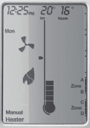
This appliance must be installed in accordance with:
         • Manufacturer’s Installation Instructions
         • Current AS/NZS 3000, AS/NZS 5601, AS/NZS 5141
         • AS 4254, HB 276-2004
         • Local Regulations and Municipal Building Codes
           including local OH&S requirements
         This appliance must be installed, maintained and removed
         only by an Authorised Person.
         For continued safety of this appliance it must be installed
         and maintained in accordance with the manufacturer’s
         instructions.

                     All Rinnai gas products sold in
                     Australia are A.G.A. certified.

Brivis                                                 2               Ducted Gas Heater OM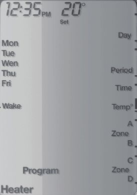
Table of Contents
 Warnings and Important Information                                                                                                                                           5
 1.1      How Does Ducted Heating Work?................................................................................................................... 7
 1.2      Efficiency.......................................................................................................................................................... 7
 1.3      Safety Warnings............................................................................................................................................... 8
 1.4      Supply Cord..................................................................................................................................................... 8
 1.5      Notes on Heater Operation.............................................................................................................................. 8
 1.6      Power Supply Interruption................................................................................................................................ 8
 1.7      Switch the System On...................................................................................................................................... 8

 2.       Outlet Guide                                                                                                                                                        9

 3.       Networker Wall Control Unit                                                                                                                                       12

 4.       Zoned Systems                                                                                                                                                     13
 4.1      Zoning Symbols............................................................................................................................................. 13

 5.       Time and Day Settings                                                                                                                                             13
 5.1      Set Time and Day.......................................................................................................................................... 13

 6.       User Settings                                                                                                                                                     14
 6.1      NC-6 User Settings in Heating Operation Display......................................................................................... 14

 7.       Programmed (AUTO) Operation                                                                                                                                       15
 7.1      Operate the System in AUTO Mode.............................................................................................................. 15
 7.2      Temporarily Override the AUTO Mode Settings............................................................................................ 15
 7.3      Skip a Programmed Heating Period.............................................................................................................. 16
 7.4      Permanently Change the AUTO Mode Settings............................................................................................ 16

 8.       Manual Operation                                                                                                                                                  17
 8.1      Operate the System with Manual Settings..................................................................................................... 17

 9.       Special Fan Operations                                                                                                                                            18
 9.1      Fan Only Operation........................................................................................................................................ 18
 9.2      Continuous Fan Operation – Networker On.................................................................................................. 18

 10.      System Messages                                                                                                                                                   18
 10.1 Read Messages............................................................................................................................................. 18
 10.2 Clear the Spanner Icon.................................................................................................................................. 18

 11.      Error Codes                                                                                                                                                       19

 12.      Reset the Heater                                                                                                                                                  20

Brivis                                                                                3                                                       Ducted Gas Heater OM
13.      Lock the Networker                                                                                                                                      20
 13.1 Set a Personal Identification Number (PIN)................................................................................................... 20
 13.2 Lock the Networker........................................................................................................................................ 20
 13.3 Unlock the Networker..................................................................................................................................... 20

 14.      Dual Networkers                                                                                                                                         21

 15.      Add-On Air Conditioning                                                                                                                                 21
 15.1 Cooling Mode Operation................................................................................................................................ 21

 16.      Heater Service and Maintenance                                                                                                                          22
 16.1 Heater Inspection........................................................................................................................................... 22
 16.2 System Shut Down........................................................................................................................................ 22
 16.3 Ductwork Maintenance................................................................................................................................... 22
 16.4 Heater Service............................................................................................................................................... 22

 17.      Before Calling For Assistance                                                                                                                           23
 17.1 Basic Checks................................................................................................................................................. 23
 17.2 Troubleshooting............................................................................................................................................. 23

 18.      Customer Care Program                                                                                                                                   24
 18.1 Contact Customer Care................................................................................................................................. 24
 18.2 Product Registration....................................................................................................................................... 24

 19.      Maintenance                                                                                                                                             24
 19.1 Routine Maintenance..................................................................................................................................... 24
 19.2 Service Maintenance Schedule..................................................................................................................... 25

 20.      Frequently Asked Questions                                                                                                                              26

 21.      Warranty                                                                                                                                                28

 22.      Contacts                                                                                                                                                36

Brivis                                                                           4                                                    Ducted Gas Heater OM
WARNINGS AND IMPORTANT INFORMATION
           READ ALL INSTRUCTIONS BEFORE USING THE APPLIANCE

 WARNING
           Always comply with the following precautions to avoid dangerous situations and to ensure
           optimum performance.
           Failure to carefully read and follow all instructions in this manual can result in equipment
           malfunction, property damage, personal injury and/or death.
           DANGER: Indicates an imminently hazardous situation which, if not avoided, will result in
           personal injury or death.
           WARNINGS: Indicates a potentially hazardous situation which, if not avoided, could result in
           personal injury or death.
           CAUTIONS: Indicates a potentially hazardous situation which, if not avoided, could result in
           minor or moderate injury or damage to the appliance. It may also be used to alert against unsafe
           practices.

           REGULATORY / INSTALLATION

 WARNING
           This appliance shall be installed in accordance with:
               • Manufacturer’s Installation Instructions.
               • Current AS/NZ 3000, AS/NZS 5601 and AS/NZS 5141.
               • AS 4254 - Ductwork for air-handling systems in buildings.
               • HB 276-2004 – A Guide to Good Practice.
               • Local Gas and Electricity Authorities.
               • “SuperSizeGuide”
               • Building Code of Australia (BCA) including local OH&S requirements.
               • Environment Authorities.
           This appliance must be installed, maintained and removed only by an Authorised Person.
           For continued safety of this appliance it must be installed and maintained in accordance with the
           manufacturers instructions.
           This appliance is heavy, use 2 people or mechanical lifting device. Improper lifting may result in
           serious injury.
           Take care when opening or unpacking this appliance. Failure to do so may result in serious injury
           or product failure.
           DO NOT modify the electrical wiring of this appliance. If the control power wiring is damaged
           or deteriorated then it must be replaced by an authorised person. Failure to do so may result in
           electric shock, fire, serious injury or product failure.
           DO NOT install the heater on an unstable or non level surface or where there may be a danger
           of it falling. It may result in death, serious injury, or product failure.
           DO NOT install the outdoor unit where noise may cause nuisance.

           The manufacturer cannot guarantee compatibility and support for anyone using 3rd party
           accessory/devices (device) on any of their appliances.
   NOTE
           The suitability, compatibility or functional performance of any 3rd party device is entirely the
           responsibility of the device’s supplier or installer.
           Any 3rd party device, technical, installation, operation, performance or other enquiries need to be
           referred to the device’s supplier or installer.
           Any adverse effects of 3rd party devices on the operation, performance or reliability of this
           appliance is not covered by the manufacturer’s product warranty.

           A NOTE ON ILLUSTRATIONS

   NOTE
           The illustrations used in this manual are for explanatory purposes only and the shape of your unit
           may vary slightly from that which is shown in this manual.

Brivis                                                 5                                  Ducted Gas Heater OM
OPERATION
WARNING
DO NOT place articles on or against this appliance.
DO NOT touch, operate or clean the unit with wet hands. It may result in electric shock or
product failure.
Turn main power off before cleaning. Failure to do so may result in fire, electric shock, or product
failure.
DO NOT use solvents, abrasives or harsh detergent to clean any part or surface of this appliance
or spray water or allow liquids to enter the unit. The enclosure of the appliance and controller can
be cleaned using a soft, damp cloth and a mild detergent.
DO NOT use or store flammable materials near this appliance. It may result in explosion or fire.
DO NOT spray aerosols in the vicinity of this appliance while it is in operation.
DO NOT modify this appliance.
If there is excessive noise, smell or smoke coming from the appliance, turn the appliance OFF,
isolate the power supply and contact a service agent.
DO NOT operate the appliance if it has been submerged into water due to flooding, contact a
service agent. Failure to do so may result in electric shock, fire, serious injury, or product failure.
This appliance is NOT intended for use by persons (including children) with reduced physical,
sensory or mental capabilities, or lack of experience and knowledge unless they have been given
supervision or instruction concerning use of the appliance by a person responsible for their
safety.
Children should be supervised to ensure that they do not play with the appliance.
DO NOT expose people, animals or plants directly to the cold or hot discharge of the appliance.
It may result in serious injury.
DO NOT use an extension cord, manually extend the power cord, or connect other appliances
to the same outlet as the heater. Poor electrical connections, poor insulation, and insufficient
voltage can cause fire.
WARRANTY EXCLUSIONS
IMPORTANT
Rinnai product warranty excludes faults and failures caused by improper use and abuse; fair
wear and tear; or failure to follow instructions regarding service and maintenance.
It is very important that you maintain your appliance and have it serviced regularly. It is a
condition of warranty that you adhere to the maintenance and service requirements as set out in
this manual. Compliance with these requirements will prolong the useful life of your appliance
and help ensure it operates efficiently.
The “Service Maintenance Schedule” section specifies specific tasks to be performed at
prescribed intervals by qualified licensed technicians.
The schedule should also be fully completed and retained as a record of who carried out the
service, the date and actions taken.
IMPORTANT: Failure to carry out the requisite maintenance, servicing and recording
requirements may void your product warranty. Please refer to ”Warranty” section for full details.
MANDATORY INSPECTION PRIOR TO INSTALLATION
IMPORTANT
Immediately report any damage or discrepancies to the Supplier of the appliance. This
appliance was inspected and tested at the time of manufacture and packaging, and released for
transportation without known damage. Upon receipt, inspect the exterior for evidence of rough
handling in shipment. Ensure that the appliance is labelled correctly for the gas and electrical
supply, and/or other services it is intended to be connected to.
For safety and warranty purposes, appliances that may be damaged or incorrect MUST NOT be
installed or operated under any circumstances. Installation of damaged or incorrect appliances
may contravene local government regulations. Rinnai disclaims any liability or responsibility
whatsoever in relation to the installation or operation of damaged or incorrect appliances.
Brivis 6 Ducted Gas Heater OMIntroduction
Congratulations on the purchase of a Rinnai heating system. To achieve the performance and efficiency expected
from this new heater, ensure the installer is a qualified tradesperson and has commissioned the unit before the
commencement of operation, and please take the time to read this manual.
In some Australian states, it is mandatory that the heater installation is issued with a certificate of compliance to
guarantee the installation workmanship. Please check with the installer or local plumbing authority or association for
this requirement. The Rinnai heater is covered by the product warranty as outlined in this manual.
Rinnai products are renowned for providing years of trouble-free performance. However, they may not operate at
their peak for all of that time without some attention. To be at their most efficient they, like most things, need a little
care. So, to ensure that every Rinnai unit is always in perfect condition, we have established the Customer Care
program for our valued customers.
The Customer Care program provides a maintenance service. This service includes cleaning the unit and ensuring
that the system is operating at maximum efficiency. Not only does this guarantee peak performance, it also allows
any minor problems to be detected early. This ensures that the system will always be ready when it is needed.
Privacy Notification
Rinnai Australia Pty Ltd will collect personal information when warranty and maintenance registration forms are
completed. This personal information is collected under the guidance of the Privacy Information Protection Act 1998.
The purpose of collecting this information is to:
• process customer requests for us to provide service activities;
• register purchases of equipment for warranty;
• register requests for a survey/quotation for heating, ventilation, and air conditioning goods and services.
The intended recipients of the information are:
• employees of Rinnai.
• federal and state governments who may require the information for administration purposes.
While the supply of the information is voluntary, if our customers cannot, or do not wish to provide the information
sought, the company may not be able to provide the services requested. If information has already been provided,
an application can be made for access or amendment of that information, or to request that it not be used.
Customers have a right of access to, and correction of, the information concerning them in accordance with the
relevant procedures under the Act.
Enquiries concerning this matter can be addressed to the Business Practices Officer using the contact details on
the back page.
Product Warranty
The product warranty excludes faults and failures caused by improper use and abuse, fair wear and tear, and/or
failure to follow instructions regarding service and maintenance. It is very important that the owner maintains the
ducted gas heater and ensures it is serviced regularly.
It is a condition of warranty that the maintenance and service requirements are adhered to as set out in this manual.
Compliance with these requirements will prolong the useful life of the ducted gas heater and help ensure it operates
efficiently. The maintenance schedule (Section 19.2) specifies tasks to be performed at prescribed intervals by
qualified licensed technicians. The schedule should also be fully completed and retained as a record of who carried
out the service, the date and the actions taken.
IMPORTANT: Failure to carry out the required maintenance, servicing and recording may void the product warranty. Please refer
to the Terms of Warranty document accompanying the ducted gas heater.
1. Ducted Heater Operation
1.1 How Does Ducted Heating Work?
This heating system consists of three major components; a heater, a ductwork system and a wall control unit.
Air is drawn from the house through a large, centrally located, return air grille into the heater where the air is warmed.
When heated, the air is distributed throughout the house via a network of smaller ducts and released into each room
through floor or ceiling outlets.
The entire process is controlled via the wall control unit, which is usually positioned in the living area on an internal
wall away from windows and doors (where possible).
1.2 Efficiency
We recommend that the following guidelines are followed to get the best performance from the heater and maximise
its efficiency:
Brivis 7 Ducted Gas Heater OM• Making sure the home is well insulated. Features such as wall-to-wall floor coverings, drapes, pelmets and even
wall insulation can help reduce energy consumption. Ceiling insulation is mandatory.
• Save energy and lower gas bills by turning the heater off at night and on again in the morning.
• Keep the temperature setting low if people are active in the house. The normal operating temperature range is
17ºC to 21ºC.
• Do not leave external doors and windows open.
• Fumes from candles, fragrant oil burners, cooking or smoking may be drawn into the system (especially if the
Return Air inlet grille is in the ceiling) and can cause staining around the heating outlets. Installing an Electronic
Air Filter in the return air grille will help to avoid this problem.
1.3 Safety Warnings
• DO NOT place any articles on or against the heater unit/add-on units.
• DO NOT use or store flammable materials near the heater unit/add-on units.
• DO NOT spray aerosols in the vicinity of the heater unit/add-on units while in operation.
• DO NOT modify the heater unit/add-on units.
• DO NOT hose the flue terminal.
• ENSURE that the controls access cover of the heater is in place whenever the unit is in operation.
• ENSURE that the flue terminals are kept clear of plant growth or any other obstructions.
This appliance is not intended for use by persons (including children) with reduced physical, sensory or mental
capabilities, or lack of experience and knowledge, unless they have been given supervision or instruction concerning
use of the appliance by a person responsible for their safety.
Children should be supervised to ensure that they do not play with the appliance.
1.4 Supply Cord
If the supply cord is damaged, it must be replaced by an authorised service representative or similarly qualified
person.
1.5 Notes on Heater Operation
When the heater is first turned on, there will be a delay before warm air is delivered from the duct outlets. Allow
approximately one minute for the burners to generate heat, before the fans start. This process ensures that the air
delivered into the house is warm.
With any ducted heating system, it is not unusual to see vapour discharging from the flue terminal when the heater
is in operation. The flue terminal may be hot during operation.
This unit has been preset and tested using typical system settings. However, the installer may have varied the fan
speed settings to suit the specific installation configuration. Please consult the installer to set the heater according
to personal needs and preferences.
The network controls within the SP and BX5 model heaters automatically adapt heater output to suit the number of
outlets that are open. Check the outlet guide for the appropriate number of outlets to open for best performance.
1.6 Power Supply Interruption
If the power supply is interrupted during heater operation, a safety function turns off the gas supply. When the
power is restored, the safety function allows the heater to resume normal operation. If the power is off for more than
approximately 2 hours the networker wall control unit (if fitted) it may require the time and day to be reset.
1.7 Switch the System On
a. Ensure the wall control unit is switched off.
b. Ensure that the gas supply tap adjacent to the heater unit is turned on.
c. Ensure the heater unit power plug is firmly connected to the 240V power point and switch on the power
supply.
d. Turn the wall control unit on. The heater can now be operated from the wall control unit.
Note: Several attempts may be required to start the heater if it is a new installation, has been shut down for an extended period, or the
gas supply has been interrupted. This is due to the need to purge air from the gas pipe.
SP and BX5 models display a busy code at the top of the networker during these ignition re-attempts. If re-ignition is not
successful, the heater locks out and a spanner icon displays. Refer to Section 10, System Messages. All heater models
automatically perform up to four re-ignition attempts before locking out, but the system may still need to be reset several times
depending on how long it takes to purge the air.
Brivis 8 Ducted Gas Heater OM2. Outlet Guide The outlet register chart (Table 1) provides recommendations based on using the Sizing Guide or a system designed using accepted design principles. These figures also relate to typical size registers and diffusers used on domestic heating systems i.e. 300 mm x 100 mm floor registers and 150 mm round ceiling diffusers, with 150 mm ductwork connection. For all systems, a minimum number of outlets (Column B and C) must remain fully open (this includes both the outlet grille and the damper in the duct) to achieve optimum turn down performance and system reliability without overheating. Similarly, ceiling outlet systems have a maximum number of outlets that can remain fully open, to ensure that the velocity through each outlet is sufficient. These maximum ceiling outlet figures relate to fully open outlets, however, the system will operate efficiently with more outlets open, if it has been properly balanced. The outlet chart is divided into four columns as follows: A. The maximum number of outlets that should remain fully open for a ceiling outlet system. B. The minimum number of outlets that should remain fully open for floor/ceiling systems where the system does not have zone dampers installed or, where there are zone dampers but these zones are not operated from a networker thermostat (e.g. wall switches). C. (Adaptive Zoning Only) The minimum number of outlets that should be fully open for floor/ceiling systems with: • zone dampers installed, • zone control via a networker thermostat using on-board zone relays or a Network 516 module, and • adaptive zoning active (hence minimum outlet number is reduced). Note: • Refer to Column C only when the networker has been configured for adaptive zoning. Otherwise, refer to Column B. • For ZonePlus configurations, refer to the ZonePlus Installation Manual. • Airflow figures are based on a total static pressure of 125Pa for 30 and 35 models and 50Pa for other models. Brivis 9 Ducted Gas Heater OM
Table 1. Outlet Register Chart

                                                          A                     B                     C

         System Model        Airflow Rate (L/s)   Maximum No. Ceiling   Minimum No. Floor/    (Adaptive Zoning)
                                                       Outlets            Ceiling Outlets       Minimum No.
                                                                                             Floor/Ceiling Outlets
 SP6 Heaters – External
 SP623EN                            715                   12                    5                     2
 SP623EN XA                         755                   13                    5                     2
 SP630EN                            850                   15                    7                     3
 SP630EN XA                         985                   17                    7                     3
 SP6 Heaters – Internal
 SP615IN                            695                   12                    5                     2
 SP623IN                            765                   12                    5                     2
 SP623IN XA                         795                   14                    5                     2
 SP630IN                           1065                   16                    7                     3
 SP630IN XA                        1095                   17                    7                     3
 SP635IN                           1130                   17                    7                    2.5
 SP5 Heaters – External
 SP521EN                            700                   12                    5                    1.5
 SP521EN XA                         740                   13                    5                    1.5
 SP530EN                            960                   16                    7                     2
 SP530EN XA                         965                   17                    7                     2
 SP5 Heaters – Internal
 SP521IN                            785                   12                    5                    1.5
 SP521IN-XA                         830                   14                    5                    1.5
 SP530IN                           1080                   17                    7                     2
 SP530IN-XA                        1140                   17                    7                     2
 SP535IN                           1160                   17                    7                    2.5
 SP4 Heaters – Universal
 SP415UN                            620                   10                    6                     2
 SP421UN                            621                   10                    6                     2
 SP430UN                            918                   16                    7                     2
 SP435UN                           1004                   17                    7                     3
 BX5 Heaters – External
 BX520EN (300mm)**                  605                   10                    5                     2
 BX520EN (350mm)**                  667                   12                    6                     2
 BX526EN (350mm)**                  944                   16                    7                     2
 BX526EN (400mm)**                 1011                   17                    7                     3
 Classic Heaters – BX3C External
 BX315C (300mm)**                   498                   8                     4                    N/A
 BX320C (300mm)**                   581                   11                    5                    N/A
 BX320C (350mm)**                   622                   11                    5                    N/A
 BX326C (350mm)**                   819                   16                    8                    N/A
 BX326C (400mm)**                   921                   16                    8                    N/A

Brivis                                                    10                                 Ducted Gas Heater OM
A B C
System Model Airflow Rate (L/s) Maximum No. Ceiling Minimum No. Floor/ (Adaptive Zoning)
Outlets Ceiling Outlets Minimum No.
Floor/Ceiling Outlets
Classic Heaters – 2PWN Internal
2PWN15 452 10 5 N/A
2PWN20 527 13 7 N/A
2PWN20 XA 561 13 7 N/A
2PWN26 858 17 8 N/A
2PWN26 XA 944 17 8 N/A
Compact Classic Heaters – Internal*
CC330 920 13 8 N/A
CC330 XA 980 14 8 N/A
CC325 600 11 6 N/A
CC325 XA 680 12 7 N/A
CC320 540 10 5 N/A
CC320 XA 625 11 6 N/A
CC315 540 10 5 N/A
* Applies to NG and LPG models
** Model and base-box duct size
Note: If fitment of supply air filters is desired, consult the product dealer to confirm compatibility with airflow requirements. When fitted,
ensure that the air filters are regularly cleaned and maintained.
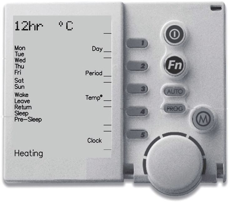
Brivis 11 Ducted Gas Heater OM3. Networker Wall Control Unit
Table 2 details the functions and symbols of the networker control unit.
Heating
Batteries
The networker does not require batteries. If the networker display is blank, check that the 240V power supply and
the thermostat cable are correctly connected.
Table 2. Networker Wall Control Unit Features
Symbol Description Symbol Description
On/Off: Turns the networker on and off. Variable Keys: Provide various functions
depending on the selected program or mode.
Functions are available only when text, a black
box, or and arrow appears on the screen beside
the key.
Function (Fn): Used in conjunction with Keys Flame: Indicates that the heater is switched on.
1 or Key 2 to activate special functions, such as Flashes during cool-down.
message repeating and networker locking.
The Fn button also activates the LED backlight.
Mode: Enables switching between a heater Fan: Displays when the heater is switched on;
and cooler when both are connected to the indicates that the fan is active. Flashes during
networker. When selected, the active mode cool-down.
appears at the bottom of the screen, e.g.
Heating.
Heartbeat: When flashing, this icon indicates Thermometer: Registers the current room
that room temperature is being sensed from this temperature. The small marker beside the
networker. thermometer indicates the temperature that the
heater is currently set to maintain.
Program (PROG): Provides access to the Padlock: Indicates that the networker is locked.
programmable settings of the networker. (Refer to Section 13.2, Lock the Networker.)
Auto (AUTO): Switches between the preset Snowman: (Add-on air-conditioning only)
program and manual operation. Indicates the refrigeration compressor is
running. Flashes when the compressor is in a
safeguard time off period.
Rotary Dial: Rotated to change settings. Provides information about the system, such as
the current time (top left), day of the week (left
side), and selected appliance (bottom).
The display also scrolls messages across the
top of the screen, for added information such as
operational states.
(Display)
Brivis 12 Ducted Gas Heater OM4. Zoned Systems
Some systems provide the option of dividing the home into different climate zones. This can be achieved by using
multiple heaters, or by using one heater and zone dampers that switch between different zones. When installed,
the zone features will have been configured by the installer and can be operated in either manual or AUTO mode.
Only zones that have been installed and configured by the installer display; labelled from Zone A to Zone D. Zones A
and B are operated by Key 4, and Zones C and D are operated by Key 5. Zones can be selected and deselected
by pressing the corresponding key.
Note: For ZonePlus systems the Owner’s Manual may be downloaded from the Brivis website.
4.1 Zoning Symbols
Zone operation utilises the following symbols:
• An arrow beside a zone indicates the zone is selected for use.
• A solid arrow indicates that the zone is open and receiving heating from the unit.
• A flashing arrow indicates that the zone has reached the desired temperature and is closed.
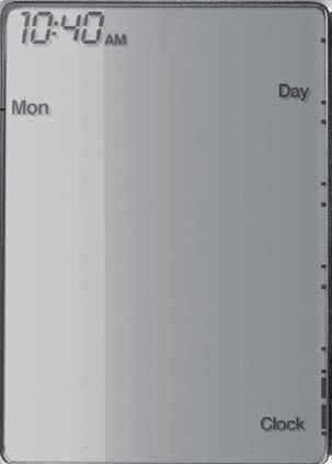
5. Time and Day Settings
5.1 Set Time and Day
a. Press the on/off button to turn the networker off.
b. Press Key 5 to enter clock setting mode. The digital clock flashes.
c. Use the rotary dial to select the correct time.
d. To set the day, repeatedly press Key 1 until the correct day of the week displays.
e. Press Key 5 to save the new settings and exit clock setting mode.
Note: If dual networkers are installed, only the master control has the ability to set the clock time and adjust program settings. The
master control can be identified by the word Clock beside Key 5, when the networkers are in the off position.
Brivis 13 Ducted Gas Heater OM6. User Settings
Accessing the user settings allows you to customise certain features on the NC-6 display and modify “Auto
Program” functions; these include:
• Clock displayed in either 12hr or 24hr time
• Temperature displayed in either °C or °F
• Day grouping (3 options) when in “AUTO” mode
• Enable or disable the “Pre Sleep” option
6.1 NC-6 User Settings in Heating Operation Display
To access and change the user settings at the NC-6 Master Controller:
1. Press Key “5” and release
2. Press and hold Key “4” until the following message begins to scroll across the top of the screen - “User setting
mode”
3. You now have access to the user settings. Please refer to Table 3. User Setting Options on page 14 and
change as required
4. Press the On/Off button to save and exit User Settings
Table 3. User Setting Options
User Input Option
Key “1” Changes the day grouping to one of the following:
- Individual days: Selected when each day flashes individually and
sequentially
- Week day and weekend Block: Selected when Mon to Fri flash and the
Sat-Sun flash
- All week days: Selected as one group when Mon to Sun are all displayed
at once
Key “2”. Enables and disables the “Pre Sleep” option
Key “3” Displays the temperature in either ºC or ºF
Key “4” Displays the time in either 12hr or 24hr format
Brivis 14 Ducted Gas Heater OM7. Programmed (AUTO) Operation
In AUTO mode, the networker has pre-programmed heater settings for the entire week, including on/off times for
wake, leave, return and pre-sleep. The default settings, based on average operation, are detailed in Table 4. Zoning
options will also appear where zone features have been installed.
Heating
7.1 Operate the System in AUTO Mode
If the preset AUTO program settings provide the desired level of comfort, then the system can simply be
operated in AUTO, as follows:
a. If more than one type of appliance is connected, turn the networker off.
b. Press the mode button until Heating displays.
c. Use the on/off button to turn the networker on.
d. Press the AUTO button until Auto Program displays. The heater operates in AUTO mode.
Table 4. AUTO Mode Default Settings
Period Time Heating
Wake 6:00am 20 Set a time and temperature to start the system and pre-warm the house before
arising in the morning.
Leave 9:00am —— Set a time and temperature to turn the heater down or off, when leaving the house
for the day.
Return 4:00pm 20 Set a time and temperature to switch the system on just before returning home.
Pre‑sleep 9:30pm 20 This feature can be used to slightly increase, or decrease the set temperature, at
the same time every night. If zoning options are in use, Pre‑sleep can be used to
switch heating on or off in selected zones, e.g. to pre‑warm bedrooms.
Sleep 10:00pm —— Sets a time and temperature for the night, when everyone is asleep. It is
recommended that the system be set to turn off (- -) overnight, to save energy and
reduce gas bills.
7.2 Temporarily Override the AUTO Mode Settings
If there are times when the preset AUTO program settings are not providing the desired level of comfort,
they can be temporarily overridden, as follows:
a. Use the rotary dial to increase or decrease the current temperature setting.
b. The word Temporary flashes at the bottom of the screen until the current period ends.
c. Key 2 (Advance Period) now offers a Cancel function. Press Key 2 to return to the AUTO preset program.
Note: Zoning (if installed) can also be temporarily overridden using these steps.
Note: The networker reverts to AUTO program after the current period ends.
Brivis 15 Ducted Gas Heater OM7.3 Skip a Programmed Heating Period
Skip the current period settings and operate at the next programmed period as follows:
a. Press Key 2 (Adv Period).
b. Key 2 (Advance Period) now offers a Cancel Adv Period function. Press Key 2 to return to the preset AUTO
program.
7.4 Permanently Change the AUTO Mode Settings
If the preset AUTO program settings do not provide the desired level of comfort, the settings can be
changed to suit requirements, as follows:
a. Turn the networker off.
b. Press the mode button until Heating displays.
c. Press the PROG button. The word Program and the digital clock begin flashing.
Time Period Selection
d. Press Key 1 (day) and select either the weekdays or the weekend.
e. Press Key 2 (period) to select the required time period.
Time Settings
f. Press Key 3 (Time/Temp) to select Time. The digital clock flashes.
g. Turn the rotary dial to adjust the time as desired for the period selected.
Temperature Settings
h. Press Key 3 (Time/Temp) to select Temp. The temperature flashes.
i. Turn the rotary dial to adjust the temperature as desired for the period selected.
Note: Selecting a Set Temperature of (- -) turns the heater off for that period. If zone features are installed, zone keys 4 and 5 are
active and zones can be selected for that period.
j. Repeat from Step d until all time periods are set as desired.
k. Press the PROG button to save the settings.
l. To review the settings, press PROG. The new settings display.
m. Press PROG to close the review.
Brivis 16 Ducted Gas Heater OM8. Manual Operation
8.1 Operate the System with Manual Settings
Note: When operating the system manually, time settings are not used because the heater is manually turned on and off.
Bypass the AUTO settings and operate the heater manually, as follows:
a. Turn the networker off.
b. If other appliances are installed on the network, press the mode button until Heating displays.
c. Turn the networker on and press the AUTO button until Manual displays. The set temperature displays at
the top left of the screen and the current room temperature at top right. If zone features are installed, zone
keys 4 and 5 are active and zones can be selected.
d. Use the rotary dial to adjust the set temperature as desired.
Note: The heater will not switch on until the current room temperature falls below the set temperature.
e. Use Keys 4 and 5 to select the zones to operate.
f. Press the on/off button to turn the system off.
Note: When manual operation is next selected, the networker will operates using these settings.
Brivis 17 Ducted Gas Heater OM9. Special Fan Operations
9.1 Fan Only Operation
The central heating system fan and ductwork can be used to improve the quality of air in the home. For
example, air quality devices such as electronic air filters can be integrated into the system to clean the air.
These can especially assist asthma sufferers. For this purpose, or to simply circulate the air in the house,
the fan can be set to run continuously without heating.
a. Turn the networker off.
b. Press the mode button to select Heating.
c. Press Key 1 (fan). The small rotating fan symbol and a column indicating fan speed, display.
d. Rotate the rotary dial to adjust the fan speed.
9.2 Continuous Fan Operation – Networker On
This option sets the fan to operate continuously, including between heating cycles. Although the fan speed
is controlled by the heater (by default set to a low, constant speed), it can be adjusted by an authorised
service representative/installer.
Note: An installer or authorised service representative is required to make this option available.
a. If required, press the mode button to select Heating.
b. Press Key 1 (fan).
If zone features are installed, zone keys 4 and 5 are active and zones can be selected.
c. Use Keys 4 and 5 to select the zones to operate.
d. Press Key 1 again to turn the fan off.
10. System Messages
While the networker is operating the system, it is also monitoring and controlling system performance. If a system
event is detected, the spanner symbol displays. When this occurs, a notification or error message is available.
Error Messages
Error messages scroll across the top of the screen with a title and code, such as:
Heater Fault ‑ H01 Code #?? For assistance call 1300 555 545.
Messages contain information to enable technicians to quickly and easily address the issue, however, many of these
may be rectified by the customer (refer to Section 11, Error Codes). If a technician is required, the technician may
request that Customer Care be contacted to report the error; the following information should be provided:
• the message
• the model, and
• the type of appliance.
Service Notification Message
When the operating hours logged for an appliance reach a predetermined duration, the spanner symbol flashes
once per second on the networker and a message displays, such as:
Fan run hours indicate it is time for a service call - For assistance call 1300 555 545.
A service call may be booked.
10.1 Read Messages
Read available messages as follows:
a. Press the Fn button and then Key 1.
b. Write down the date and the message.
c. To repeat the message, press Fn then Key 1.
Note: If the message does not repeat, the event may have passed. It is a good idea to note down the date that these messages are
noticed, even without capturing the message content.
10.2 Clear the Spanner Icon
To clear the spanner icon, press Key 4 on the master controller (RESET).
If the scrolling message and RESET are not displaying, press Fn then Key 1.
Brivis 18 Ducted Gas Heater OM11. Error Codes
Customers may safely rectify the following faults by stepping through the corrective actions listed. If a fault persists,
contact Customer Care.
Error code 40, 41, 42 and 43
These errors indicate that an overheat condition has occurred. The fan will operate at maximum speed.
Corrective actions:
• Check there are sufficient outlets open on the duct system.
• Check that the floor/ceiling register and baffle is fully open and not restricting air movement.
• Check the return air filter (if fitted) is sized correctly, is clean and no obstructions have occurred (or been placed
in front of) the return air grille.
Error code 46, 47 and 55
These errors indicate that the heater has failed to ignite within the specified time.
Error code 50
This error indicates that the heater has locked out after four ignition attempts. This error can be cleared by using the
reset button to restart the heater, however, the unless the condition has been rectified, the error is likely to occur
again.
Corrective actions:
• Check the gas supply is turned on at the meter, and at the appliance gas cock.
• Check if other gas appliances are operating such as Gas Cooker and Hot Water Service (if installed).
• Check the gas cylinders have gas, and the cylinder valve is open (LPG only).
• Check that there is gas supply to the home. Contact the gas provider to confirm this. There may be works in the
area or a problem with the supply.
• The heater may require a general service.
Error Code 53
This error indicates the heater has locked out due to multiple overheat occurrences.
The primary cause is typically associated with insufficient airflow.
Corrective actions:
• Check there are sufficient outlets open on the duct system.
• Check that the floor/ceiling register and baffle is fully open and not restricting air movement.
• Check the return air filter (if fitted) is sized correctly, is clean and no obstructions have occurred (or been placed
in front of) the return air grille.
• Reset the appliance and if error 53 persist contact your installer.
Error code 56
This error indicates that a lockout has occurred on the pressure switch, usually caused by too much restriction on
the flue pipe, or condensate drain (SP6 models).
Corrective actions:
• Check the flue pipe for blockages
• Check the condensate piping for blockages (SP6 models).
Note: Any other error codes that appear on the screen could indicate that the heater is not operating due to a malfunction or fault with
the electronic control module. This error may be reset at the power supply, however, if the error persists, contact Customer Care.
Brivis 19 Ducted Gas Heater OM12. Reset the Heater
If heater operation has been interrupted, Reset may appear beside Key 4 while a message scrolls across the top
of the screen. The issue may be resolved by resetting the heater. However, contact Customer Care if any of the
following occur after resetting:
• the heater does not resume normal operation
• the error continues to persist
• other messages appear after clearing the fault.
RESET Not Displaying
a. If RESET is not displaying (adjacent to Key 4), press Fn then Key 1. The error message scrolls across the
top of the screen and RESET displays.
Reset the Heater
b. Press Key 4 to restart the heater. If the heater is still operating but the networker is showing the error
message and service symbol, try resetting again. If other messages appear, contact Customer Care.
Error Persists – Initial Actions
c. If the error persists, turn the networker off using the on/off button and wait for approximately 2 minutes.
d. Turn the networker on. This may reset the heater and restore normal operation.
e. If the error persists, disconnect the power supply from the unit at the power point (located near the heater
unit) and wait for approximately 1 minute.
f. Connect and switch on the power supply. If normal operation still does not resume, contact Customer Care.
13. Lock the Networker
To prevent unwanted adjustments to the heater settings, the networker can be locked with the use of a 4-digit PIN. In
the case of dual networkers, locking one also locks the other, although the PIN must be set at the master networker.
The slave networker can lock and unlock the system, but cannot access the PIN.
Note: If at any time an incorrect number is entered, press the AUTO button to clear all digits, then re-enter the PIN.
13.1 Set a Personal Identification Number (PIN)
a. DO NOT ENTER NUMBERS at this step. Press the Fn button followed immediately by Key 2. A message
displays: Enter Your PIN number to lock the system. Continue to Step b.
b. DO NOT ENTER NUMBERS at this step. Press the mode button once. A message displays: User PIN
reset – Enter master PIN. Continue to Step c.
c. Press the mode button once again. A message displays: User PIN number 1 alteration - Enter current PIN.
d. Enter the current PIN: The factory default PIN is 1111. If a custom PIN has been previously configured,
enter the custom PIN. A message displays: Enter the new PIN.
e. Enter the new 4-digit PIN using Keys 1 to 5. A message displays: Repeat the entry of the new PIN.
f. Re-enter the new PIN. A message displays: Valid PIN – PIN altered.
g. Press the on/off button to exit at any time.
13.2 Lock the Networker
Lock the networker using the PIN, as follows:
a. Press the Fn button followed immediately by Key 2. Enter Your PIN to lock the system displays.
b. Enter the current 4-digit PIN. System locked out! displays and the padlock icon flashes indicating that the
networker is locked.
13.3 Unlock the Networker
a. Press the Fn button followed immediately by Key 2. Enter Your PIN to unlock the system displays.
b. Enter the current 4-digit PIN. System unlocked! displays.
Note: If an invalid PIN is entered, the message Invalid PIN entered – Try again scrolls across the screen. The user has three attempts
at entering a valid PIN. On the third failed attempt, the message Invalid PIN entered! displays and the networker aborts the PIN
entry. The unlock process will need to be repeated.
Brivis 20 Ducted Gas Heater OM14. Dual Networkers
It is possible to have two networkers connected to the system, with one configured as master and the other as slave.
The dual networkers operate together and the heater settings are common; if an adjustment is made on one of the
networkers it is immediately reflected on the other. When locking one networker, the other will also lock, and the
system can be unlocked from either.
The benefit of dual controllers is the convenience of make adjustments to the settings at either of the networker
locations. The networkers can also be configured as remote temperature sensors when used with zoning.
Ask the installer for more information.
Note: If dual networkers are installed, time and program settings can be adjusted from the master control unit only. The master control
unit is identified by the word Clock beside Key 5 while the networkers are turned off.
15. Add-On Air Conditioning
15.1 Cooling Mode Operation
If the central heating system has had add-on air conditioning installed, the networker operates the air conditioning
in the same way it does for central heating, with the following differences:
• The air conditioner operates to bring the room temperature down to the set temperature, whereas the heater
brings the room temperature up to the set temperature.
• A snowman indicates that the system is in Cooling mode (the refrigeration unit is operating).
• If the snowman is flashing, the refrigeration unit is in a delay period. This is normal.
Select Cooling Mode
Use the mode button to select Cooling (instead of Heating).
Programmed (AUTO) Operation
Follow the steps in 7.1 (Operate the System in AUTO Mode), but at Step 7.1.b, select Cooling mode.
Fan Only Operation
Follow the steps in 9.1 (Fan Only Operation), but at Step 9.1.b, select Cooling mode.
Brivis 21 Ducted Gas Heater OM16. Heater Service and Maintenance
The recommended frequency for cleaning the heater depends on local conditions, so inspections should be
performed regularly.
16.1 Heater Inspection
a. Check that the power lead is in good condition. If it is damaged, call Customer Care for assistance.
b. If a return air filter is fitted (in the return air grille), the filter requires regular cleaning and should be checked
fortnightly. A blocked filter significantly affects heater performance and efficiency.
16.2 System Shut Down
To shut down the heater (e.g. for summer or holiday periods):
a. Turn off the external gas cock.
b. Switch off the power supply to the heater unit.
16.3 Ductwork Maintenance
The company does not warrant any duct work or installation. It is recommended that ducting is cleaned every
3 years, although it may be beneficial for allergy sufferers to have the ducting cleaned more frequently.
16.4 Heater Service
To ensure that the heater continues to operate at peak efficiency, it should be serviced at 2 year intervals by
authorised personnel trained to service these models. Please contact Customer Care for authorised service
representatives.
The heating unit service includes all maintenance and adjustments required to the following components:
• Burners
• Ignition system
• Fan assembly
• Heat exchanger.
For more information please refer to the 'Service Maintenance Schedule' section
Note: To maintain the product warranty, the servicing tasks must be conducted only by authorised personnel trained in the service of
these heaters. Please contact Customer Care for an authorised service representative.
Note: Service maintenance is not covered under warranty and is a chargeable service. All heaters must have safe and reasonable
access and be installed in compliance with the installation instructions supplied with the heater. Some installations require two
service personnel to attend, in accordance with Health and Safety requirements.
Brivis 22 Ducted Gas Heater OM17. Before Calling For Assistance
If the heater does not seem to be operating correctly, please perform the following checks before calling for
assistance.
17.1 Basic Checks
Perform the following checks before calling for assistance:
a. Ensure that the flue terminal is in place (whenever the unit is operating).
WARNING! The flue outlet can become very hot. DO NOT touch any system components in the vicinity of the flue outlet while the
system is operating.
b. Ensure that the air intake (located at the burner end of the heater roof panel) is clear of leaves and
obstructions.
c. Ensure that the flue terminal is clear of leaves and obstructions.
d. (SP6 models) Ensure that the condensate tube is clear. A blockage will seriously affect performance and
may shut down the heater.
e. Check Section 17.2, Troubleshooting for a solution to the problem.
17.2 Troubleshooting
Symptom Corrective Action
Error message Refer to Section 10, System Messages and follow the checks.
An error message is displaying.
Blank display Check that the power supply to the heater unit is correctly connected and
The networker display is blank. switched on.
Check that the power supply to add-on appliances is correctly connected and
switched on.
Check that the thermostat cable is correctly connected.
Unit turning on/off Check the programmed settings in the networker/programmable wall control
The appliance is unexpectedly turning on or unit (refer to Section 7.1). Adjust the settings if necessary (Sections 7.2 or
off. 7.4) or change to manual mode (Section 8.1).
Whistling Clean the return air grille and filter (if installed) (Section 19.1).
There is a whistling noise.
Unit will not turn on Note that the heater will not operate if the room temperature is higher than
The appliance will not turn on at all, or will not the temperature setting. Check that the set temperature is lower than the
operate in heating mode (or cooling mode if room temperature (refer also to Section 15.1).
add-on air conditioning is installed). Ensure that the circuit breaker (i.e. in the house meter box) is set (has not
tripped).
Reset the heater at the power supply (Section 12).
Check the gas supply is turned on at the heater and at the gas meter.
Fan not turning off Check that the Fan Only option has not been selected (Section 9.1).
The fan is running continuously. Check that sufficient vents are open (Table 1).
Clean the return air grille and filter (if installed) (Section 19.1).Check that the
ducting has not been crushed or collapsed. If damage is evident, contact
Customer Care.
No airflow This may be an installation issue, particularly if the system is configured for
There is no air coming out of some vents. zoning. Contact the installer.
Padlock symbol This indicates that the child proof lock has been activated (Table 1 and
The padlock is displaying. Section 13.2).
For Your Records
Model Number: Serial Number: Install Date:
Installed by:
Installer Contact:
Brivis 23 Ducted Gas Heater OM18. Customer Care Program
Our products are renowned for providing years of trouble free performance. However, without some attention they
may not perform at their peak all of that time. Like most things, to perform most efficiently they need a little care. So
to ensure that every unit is always in top condition, we have established the Care Program for our valued customers.
After becoming a member of our Care Program, a courtesy call will be made regarding maintenance service to the
unit. This service includes cleaning the unit and ensuring that the system is operating at maximum efficiency. Not
only does this guarantee peak performance, it also allows any minor problems to be detected early. Which ensures
that the system will always be ready needed.
If more than routine maintenance is required, the task can be attended to at the time of the service (additional
charges may apply). This repair will be guaranteed for 3 months (for labour) and 12 months (for parts).
18.1 Contact Customer Care
Refer to the contact details on the back page. Before contacting Customer Care, ensure all corrective actions have
been attempted and gather the following details:
• the message
• the model, and
• the type of appliance.
Preferential Offers
The Customer Care program is designed to help our customers get the most out of their heating system. We may
make contact with preferential offers for preventative maintenance services, which will keep the heater in great
condition.
18.2 Product Registration
If in Australia, to register your product warranty online please visit www.rinnai.com.au/support-resources/warranty-
registration/
19. Maintenance
19.1 Routine Maintenance
Return Air Filter
Where fitted, the return air filter must be cleaned at least every two weeks during the heating season. A dirty air
filter will reduce the efficiency, effectiveness and air quality of the system. The filter is usually located in the return
air grille, in either a wall or the ceiling within the home.
To clean washable filters, remove the filter and clean with a vacuum cleaner. The filter may also be washed with
warm soapy water. Ensure the filter is completely dry before installing it.
IMPORTANT: Never operate the system without the return air filter in place if add-on air conditioning is installed.
Heater Unit
If the heater is installed externally, periodic inspection is required to ensure vegetation has not grown around the unit
(plants, weeds etc.). The cabinet should be kept clean and have the recommended clearances maintained. Ensure
there is no water build up (including from condensate drain) on or around the unit.
Note: Preventative Maintenance Services are chargeable and not covered under the product warranty. The heater needs to have
reasonable and safe access and be installed in line with the installation instructions supplied with the heater. An extra charge
may apply if the company is required to allocate two service personnel to enable compliance with safety regulations.
Brivis 24 Ducted Gas Heater OM19.2 Service Maintenance Schedule
After the date of installation by a qualified licensed technician, the ducted gas heater should be serviced at two-year
intervals in accordance with the schedule (Table 5). Failure to do so during the product warranty period may void
the warranty. Scheduled servicing and maintenance will prolong the useful life of the unit and help keep it running
safely and at optimum efficiency.
Table 5. Service Maintenance Schedule
Date of Installation / / Installed By:
YEAR OF SERVICE 2 4 6 8 10 12
Service Date / / / / / / / / / / / /
Service Company / Technician
ELECTRICAL
Wiring
Supply Air Fan Motor
Supply Air Fan Capacitor
Combustion Fan Motor (if applic)
Over Heat Switches
Printed circuit boards
HEATING ASSEMBLY
Burners and Injectors
Ignition system
Flame sensor
Thermistor Set Point °C °C °C °C °C °C
Gas inlet pressure - Flowing kPa kPa kPa kPa kPa kPa
Burner Pressure (High rate) kPa kPa kPa kPa kPa kPa
Burner Pressure (Low rate if kPa kPa kPa kPa kPa kPa
applic)
Combustion Pressure (if applic) kPa kPa kPa kPa kPa kPa
Condensate Pressure (if applic) kPa kPa kPa kPa kPa kPa
CO level PPM PPM PPM PPM PPM PPM
MAJOR COMPONENTS
Heat exchanger
Cabinet
Combustion air intakes
CONTROLS
Thermostat(s)
Zone Controls (If Applic)
SYSTEM OPERATION
Sequence of operation
Return Air Temp °C °C °C °C °C °C
Outlet Air Temp
°C °C °C °C °C °C
(closest register to heater)
Thermistor Temp (If Applic) °C °C °C °C °C °C
Zone Operation (If Applic)
GENERAL INSTALLATION-RELATED AND 3rd PARTY COMPONENTS (NOT RINNAI PRODUCTS) *
Return Air grille and filters
Flue system
Ducting
Flue termination / cowl
Gas connection
Condensate drain (if applic)
Zone motors
CONSUMABLES**
Fan Capacitor
Igniter
Flame Sensor
* Installation and other field-supplied components are not covered by the product warranty. These include, but are not limited to, control wiring, ducting, return air
filter(s) grille, register, diffuser, zone motors, controls/thermostats, pipework, fabricated or added components and gas and electrical connections to the appliance.
These should be inspected as they can affect the performance, reliability and safety of the heater.
** Units contain consumable items that may require periodic replacement and are not covered by product warranty (e.g. capacitors, flame sensors, igniters, filters,
batteries)
ACTION CODES
Inspected - Working Correctly - No Action Required Adjusted Part Cleaned Part Replaced Part Repaired Part Referred to Installer
ü A C R RP RI
Brivis 25 Ducted Gas Heater OMYou can also read


