Current State and Challenges of Natural Fibre-Reinforced Polymer Composites as Feeder in FDM-Based 3D Printing
←
→
Page content transcription
If your browser does not render page correctly, please read the page content below
polymers
Review
Current State and Challenges of Natural Fibre-Reinforced
Polymer Composites as Feeder in FDM-Based 3D Printing
Nishata Royan Rajendran Royan * , Jie Sheng Leong, Wai Nam Chan, Jie Ren Tan
and Zainon Sharmila Binti Shamsuddin

                                          School of Engineering, UOW Malaysia KDU University College, Jalan Kontraktor U1/14, Seksyen U1, Glenpark
                                          U1, Shah Alam 40150, Selangor, Malaysia; 0118234@kdu-online.com (J.S.L.); 0118586@kdu-online.com (W.N.C.);
                                          0118863@kdu-online.com (J.R.T.); zainon.s@kdu.edu.my (Z.S.B.S.)
                                          * Correspondence: ry_nish@yahoo.com or nishata.r@kdu.edu.my

                                          Abstract: As one of the fastest-growing additive manufacturing (AM) technologies, fused deposition
                                          modelling (FDM) shows great potential in printing natural fibre-reinforced composites (NFRC).
                                          However, several challenges, such as low mechanical properties and difficulty in printing, need to be
                                          overcome. Therefore, the effort to improve the NFRC for use in AM has been accelerating in recent
                                          years. This review attempts to summarise the current approaches of using NFRC as a feeder for AM.
                                          The effects of fibre treatments, composite preparation methods and addition of compatibilizer agents
                                          were analysed and discussed. Additionally, current methods of producing feeders from NFRCs were
                                          reviewed and discussed. Mechanical property of printed part was also dependent on the printing

                                   parameters, and thus the effects of printing temperature, layer height, infill and raster angle were
                                          discussed, and the best parameters reported by other researchers were identified. Following that, an
Citation: Rajendran Royan, N.R.;
Leong, J.S.; Chan, W.N.; Tan, J.R.;
                                          overview of the mechanical properties of these composites as reported by various researchers was
Shamsuddin, Z.S.B. Current State and      provided. Next, the use of optimisation techniques for NFRCs was discussed and analysed. Lastly,
Challenges of Natural                     the review provided a critical discussion on the overall topic, identified all research gaps present in
Fibre-Reinforced Polymer                  the use of NFRC for AM processes, and to overcome future challenges.
Composites as Feeder in FDM-Based
3D Printing. Polymers 2021, 13, 2289.     Keywords: natural fibre; additive manufacturing; filament; surface treatments; optimisation; printing
https://doi.org/10.3390/                  parameters; mechanical properties
polym13142289

Academic Editors: Vincenzo Fiore
and Fabrizio Sarasini                     1. Introduction
                                               In recent years, the scientific and industrial communities have begun to acknowledge
Received: 12 May 2021
Accepted: 28 June 2021
                                          the need for environmentally friendly processes, materials and waste management. As
Published: 13 July 2021
                                          environmental awareness is on the rise, product designers and engineers recognise the
                                          impacts of their decisions to use non-renewable resources or non-biodegradable resources.
Publisher’s Note: MDPI stays neutral
                                          The trend in the industry has begun to shift from using conventional plastics, which are
with regard to jurisdictional claims in
                                          mostly non-biodegradable, to using bio-composites which depend on the polymer matrix
published maps and institutional affil-   that can be biodegradable or carbon neutral. This is primarily due to the great impact of
iations.                                  synthetic polymers towards the environment. As part of the efforts to increase the recycling
                                          of plastics and reduce its production, researchers have developed natural fibre-reinforced
                                          composites (NFRC). These composites are polymers mixed with natural fibres, such as
                                          hemp, jute, rice stalk, kenaf and rice husk. The result is a material that has far superior
Copyright: © 2021 by the authors.
                                          mechanical properties and reduced cost, depending on the type of polymer matrix or even
Licensee MDPI, Basel, Switzerland.
                                          biodegradable [1]. NFRCs are gaining popularity mainly due to their high strength to
This article is an open access article
                                          weight ratio, and thus they can be 25% to 30% stronger than glass fibre composites of
distributed under the terms and           the same weight [2]. Because of its various benefits, the global use of NFRCs is starting
conditions of the Creative Commons        to grow rapidly. In recent reports, the NFRC market value in 2016 was 4.46 billion USD
Attribution (CC BY) license (https://     and is forecasted to grow with a compound annual growth rate of 11.8% from 2016 to
creativecommons.org/licenses/by/          2024 [2]. The use of NFRCs is mainly to produce housing decks and railings but has recently
4.0/).                                    gained popularity in the automotive sectors with manufacturers producing car interiors

Polymers 2021, 13, 2289. https://doi.org/10.3390/polym13142289                                           https://www.mdpi.com/journal/polymers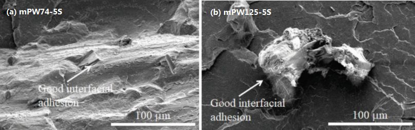
Polymers 2021, 13, 2289                                                                                           2 of 19

                          from NFRCs. Current processing techniques for NFRCs do not differ much from the
                          processing of conventional plastics. Techniques, such as extrusion, compression moulding
                          and injection moulding are used to process and form NFRCs just as they would be used for
                          conventional plastics [3]. As mankind steps into the fourth industrial revolution, the focus
                          has shifted to interconnectivity, automation, machine learning and real-time data. The
                          digitalisation of the manufacturing industries is rising rapidly [4]. There has been a rise in
                          the need for rapid prototyping and ability to produce customised parts quickly and at a low
                          cost. Conventional methods of manufacturing remove material from a large piece of stock,
                          which is known as subtractive manufacturing. These processes are sometimes complicated
                          and time-consuming for complex parts as many parameters need to be considered, such as
                          tool speed, draft angles and tooling types. Even with computer numerical control (CNC)
                          technology, the cost of producing a one-off part with CNC is much higher than using
                          additive manufacturing (AM) techniques. Therefore, researchers have identified AM as
                          one of the more essential components in the rise of the fourth industrial revolution [5].
                          Almost all of the AM technologies operate based on the same principle, whereby a part is
                          produced through the deposition of material layer by layer. The part starts as a computer-
                          aided design (CAD) model, which is then loaded into the special software known as a
                          slicer. The slicer slices the CAD model into the desired layer height and produces the code
                          to control the printer for each layer. Currently, AM technology is more widely used for
                          polymers. However, although rare, there are commercially available machines that can
                          perform additive manufacturing on metal [6]. As AM technology gains popularity amongst
                          researchers and the industrial sector, there have been efforts to utilise NFRCs in AM. One
                          of the most predominant and popular techniques for AM is fused deposition modelling or
                          sometimes known as fused filament fabrication [7], whereby a polymer filament is extruded
                          through a heated nozzle while the printer traces out the cross-section of each layer.
                                The use of NFRCs in AM is still a relatively unexplored field as literature on this
                          topic is limited. However, the ability to use NFRCs in AM proves to be beneficial as it can
                          greatly speed up the prototyping process when working with NFRCs. As compared to
                          conventional processes like the injection moulding, a mould needs to be produced before
                          the prototype can be tested. These processes are costly and limit the number of prototypes
                          that can be produced. If NFRCs can be used in AM reliably, the prototyping process can be
                          significantly hasten and at a much lower cost. Furthermore, because there is no need for a
                          mould, more iterations of a product can be tested.
                                Therefore, the target of this review is to provide a background of the current state of
                          using NFRCs in AM. The review aims to provide an insight into how NFRCs are currently
                          used for AM. The parameters of all stages, involving from raw materials to the final printing
                          process are discussed to provide readers with an insight into what is involved and what
                          affects the properties of a NFRC for use in AM. First, an overview of the currently available
                          AM technologies and works which utilise NFRCs in AM is provided. Next, preparation
                          methods and parameters involved in producing the NFRCs are discussed, followed by the
                          process of producing the filament for use in AM. Printing parameters involved and how
                          they affect the mechanical performance of the composite are discussed in the following
                          sections. Finally, the mechanical properties reported by various researchers who use NFRCs
                          in AM are discussed, followed by an overview of how optimisation methods are employed
                          to optimise the mechanical properties of these composites.

                          2. Additive Manufacturing Technologies
                               Additive manufacturing, commonly referred to as 3D printing is the process of fabri-
                          cating three-dimensional solid objects from a digital machine. The object is typically created
                          by depositing materials layer by layer until the overall object is fabricated successfully. 3D
                          printing is getting more popular as compared to conventional machining techniques, such
                          as milling, drilling, cutting, etc. AM technology is superior to conventional techniques
                          when the object complexity increases. A few technologies that are generally used in 3D
                          printing include fused deposition modelling (FDM), whereby a polymer material is ex-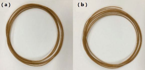
Polymers 2021, 13, 2289                                                                                           3 of 19

                               truded layer by layer to form a 3D object. In stereolithography (SLA), a photosensitive
                               resin is hardened by a UV projector layer by layer. Meanwhile, in selective laser sintering
                               (SLS), a laser sinters polymer or metal powder on a powder bed and forms each layer.
                               Direct write (DW), which is very similar to FDM but does not involve material heating, is
                               directly extruded. This technique is usually used for clay or concrete. Lastly, binder jetting
                               (BJ) is very similar to SLS but instead of laser sintering a binder is injected onto a powder
                               bed to form each layer [8]. FDM-based 3D printing is a popular additive manufacturing
                               technology that is widely used, with thermoplastic materials which have a melting point
                               of lower than 300 ◦ C. For the printing process, the feeder, which is commonly known as a
                               filament, is fed into the 3D printer, whereby the polymer filament is melted and extruded
                               from a temperature-controlled nozzle, also known as the extrusion head, onto a build
                               platform. Depending on the type of polymer, the build platform can be heated or left as
                               it is. The object is created by the layering of thermoplastic at a certain degree of accuracy,
                               whereby either the nozzle or build platform moves in the x-axis, y-axis and z-axis. Type of
                               thermoplastics material that works in the process of FDM includes acrylonitrile butadiene
                               styrene (ABS), polylactide acid (PLA) and high-density polyethylene (HDPE).
                                      However, there are few significant drawbacks of FDM as compared to stereolithog-
                               raphy (SLA) and selective laser sintering (SLS), as well as similar standard processing
                               methods (e.g., injection moulding). The quality and mechanical properties of the printed
                               product are not as good, mainly due to the layering technique in printing which adds
                               more points of contact/failure, and the inevitable presence of voids. Furthermore, the
                               mechanical properties of 3D-printed objects are anisotropic and highly dependent on the
                               processing parameters [8]. On the other hand, the small nozzle size of this technology
                               could have a drawback on printing composites like NFRCs because the fibres exist as small
                               particles in a polymer matrix. Moreover, it is not always possible to produce a homogenous
                               mix of polymer and natural fibre matrices, whereby agglomeration might occur in the
                               filament which will clog the nozzle. This phenomenon is shown in Petchwattana [9] studies,
                               in which a modified PLA/Teak wood flour composite filament was produced and the
                               specimen with 125-µm particles clogged the printer nozzle. Figure 1 shows the composite
                               filament for both 74 µm and 125 µm teak wood flour filler. The SEM micrograph of the
                               modified PLA/Teak wood flour composite filament is shown in Figure 2, whereby good
Polymers 2021, 13, x           interfacial adhesion can be seen. Nevertheless, due to the large particle size the specimen
                               with 125-µm particles still clogged the printer nozzle.

                                Figure
                               Figure 1. 1. PLA/teak
                                         PLA/teak  woodwood
                                                         flourflour
                                                               (TWF)(TWF)    composite
                                                                      composite   filament filament   of TWF
                                                                                           of (a) 74-µm  (a) 74-µm   TWFTWF
                                                                                                              (b) 125-µm (b) [9]
                                                                                                                              125-µm   T
                                Licensed
                               Licensed     under
                                         under    Creative
                                               Creative      Commons
                                                        Commons           Attribution
                                                                  Attribution            4.0 International
                                                                              4.0 International License.      License.
Polymers 2021, 13, 2289 4 of 19
Figure 1. PLA/teak wood flour (TWF) composite filament of (a) 74-µm TWF (b) 125-µm TWF [9]
Licensed under Creative Commons Attribution 4.0 International License.
FigureFigure
2. SEM2. micrograph of modified
SEM micrograph PLA/TWF
of modified PLA/TWF composite
composite filament of(a)
filament of (a)74-µm
74-µm TWF
TWF (b)(b) 125-µm
125-µm TWFTWF [9] Licensed
[9] Licensed
under
under Creative Commons Creative
Attribution 4.0 Commons
InternationalAttribution
License. 4.0 International License.
2.1. Thermoplastics forforAdditive
2.1. Thermoplastics Additive Manufacturing
Manufacturing
Thermoplastics
Thermoplastics polymers are
polymers are plastics
plasticsthat
thatreturn to the
return solidsolid
to the state state
upon upon
coolingcooling
after after
being moulded above the threshold temperature [10]. In terms of choosing a suitable
being moulded above the threshold temperature [10]. In terms of choosing a suitable
polymeric matrix material, thermoplastics are the most compelling choice. This is due to its
polymeric
variousmatrix material,
advantages, thermoplastics
such as are the most
low moisture absorption, compelling
mechanical choice.
properties This is due to
and infinite
its various advantages, such as low moisture absorption, mechanical properties
shelf life [11], low cost [12], better design flexibility and simple processing technique [13]. and
infinite shelf thermoplastics
Moreover, life [11], lowtend cost [12],attached
to stay betterduring
design theflexibility
3D-printingand simple
process processing
[14]. Poly-
meric matrices can be categorised into non-biodegradable and biodegradable
technique [13]. Moreover, thermoplastics tend to stay attached during the 3D-printing polymers. A
variety of standard thermoplastics that are suitable and generally
process [14]. Polymeric matrices can be categorised into non-biodegradable and referred to as ‘plastics’
include acrylonitrile butadiene styrene (ABS), polylactide acid (PLA), polypropylene (PP)
biodegradable polymers. A variety of standard thermoplastics that are suitable and
and polyethylene (PE) [15]. However, in terms of additive manufacturing, only polymers
generally referred
with working to as ‘plastics’
temperatures of below 300include acrylonitrile
◦ C are suitable, butadiene
as FDM printing styreneis (ABS),
temperature
polylactide
around 300 C [16]. The comparison of melting temperatures of some common thermo-in terms
acid ◦ (PLA), polypropylene (PP) and polyethylene (PE) [15]. However,
of additive manufacturing,
plastics is shown in Table 1.only polymers
As seen in Tablewith
1, all working temperatureshave
common thermoplastics of below 300 °C are
a melting
temperatures below 300 ◦ C, which indicate the suitability of these thermoplastics to be
suitable, as FDM printing temperature is around 300 °C [16]. The comparison of melting
utilised in FDM
temperatures 3D printing.
of some common thermoplastics is shown in Table 1. As seen in Table 1, all
common thermoplastics have a melting temperatures below 300 °C, which indicate the
Table 1. Melting temperature of different thermoplastic.
suitability of these thermoplastics to be utilised in FDM 3D printing.
Thermoplastic Melting Temperature (◦ C) Ref.
Polypropylene (PP) 150–160 [17–19]
Low density polyethylene (LDPE) 105–115 [20]
High-density polyethylene (HDPE) 120–190 [15,20]
Polyethylene terephthalate (PET) 235–260 [19]
Acrylonitrile butadiene styrene (ABS) 190–250 [15,21]
Polylactic Acid (PLA) 120–170 [15]
ABS polymer is considered as one of the most common materials that are widely
used as the filament in AM [8]. Nowadays, ABS-made applications in various industries
can be found easily, with their wide range of manufacturing methods, including injection
moulding and filament for 3D printing [22]. It comprises the combination of acrylonite,
butadiene and styrene monomers to form a single polymer with great mechanical perfor-
mance [15], durability as well as ease to print [8]. With stresses above their tensile strength,
ABS has strong durability, but elasticity modulus and hardness are higher. Meanwhile,
PLA is one of the most popular thermoplastic polymers because it is inexpensive with high
modulus and strength [23]. Its low melting point requires lesser energy in 3D printing [24].
Its renewability and biodegradability have made it popularly used in a wide range of
applications in the industry, especially in additive manufacturing. Besides, PLA doesPolymers 2021, 13, 2289 5 of 19
not emit any unwanted gases or unpleasant smells during the process [25]. Melnikova
et al. [26] had successfully produced a flexible cloth with PLA by using FDM technology.
PLA had also been added with various compatibilizers or reinforcing agents to mainly
enhance its properties [27].
In another case, high-density polyethylene (HDPE) poses excellent mechanical prop-
erties, such as high stiffness and melting point, as well as high compressive tensile strength
that outperforms other polyethylenes (e.g., low density polyethylene) [15,28,29]. It has a
high strength-to-density ratio as compared to another thermoplastic. With its advantages,
such as watertight, lightweight yet strong, recyclable and FDA approved, it has become
one of the ubiquitous plastics used in different applications and commercial products.
Schirmeister et al. [30] reported the success of printing HDPE by FDM technology with
similar mechanical properties as compared to the injection-moulded HDPE, without signif-
icant warpage and void formation. HDPE is also a reusable thermoplastic polymer, unlike
thermoset polymers [31]. Moreover, HDPE is easy to transform into new material through
recycling. Recycling plastics could cause a significant impact on the environment, leading
to more sustainability. Regardless, a recycled high-density polyethylene (rHDPE) still
possess its unique characteristics even as a recycled material, such as chemical resistance,
moderate tensile and impact strength, as well as excellent abrasion-resistant properties [32].
Even though research on rHDPE for additive manufacturing is scarce, the availability of
HDPE waste had encouraged efforts to use recycled materials for more beneficial use,
such that recycled HDPE from milk jugs were adapted to 3D printing in various recycling
projects [31]. Baechler et al. [33] also reported the success of using the extruded recycled
HDPE polymer to produce increasing successful parts with the 3D printer. Moreover,
Angatkina [31] reported that rHDPE is suitable for 3D printing without any significant
differences in mechanical properties as compared to the pure HDPE polymer.
2.2. Natural Fibre-Reinforced Composites in Additive Manufacturing
Natural fibres (NF) are known as hair-like raw material that is obtained from animals,
plants or mineral sources. The main difference between animal and plant fibre is that
animal fibre is mainly made out of protein, whereas plant fibres are composed of cellulose.
Examples of natural fibre that is derived from plants include rice husk, wheat, hemp,
bamboo and cotton. Thiranan Kunanopparat et al. [34] reported that the mechanical
properties of wheat composites were less sensitive to thermal treatment when the fibre
content was increased. The processing temperature was reported to be an important
parameter that affected the physical adhesion, whereby this physical adhesion played
a big role in the mechanical properties of the composites. Chen et al. [35] reported that
bamboo fibres have much lower volumes of fracture behaviours, high proportions of fibre
dissociations and matrix failure due to its hierarchical fibrous woven structure. On the
other hand, Sueli Aparecida de Oliveira et al. [36] reported that composites that have
natural cotton fibres as fillers exhibited a reduced environmental impact as compared
exclusively to PLA or PLA/thermoplastic starch (TPS)-based thermoplastics. Moreover, the
natural cotton fibre composites had a better overall performance, under the eco-efficiency
perspective. V. Mazzanti et al. [37] reported that the presence of even small amounts of
hemp fibres accelerates PLA degradation to an extent similar to that of residual water in
non-dried pure PLA. A natural fibre that can be found abundantly and replenished in a
predictable period is known as renewable natural fibre. This NF is commonly used as
a low-cost alternative to synthetic fibres (e.g., nylon) mainly due to its biodegradability,
cost-effectiveness, satisfactory mechanical properties and low density [38]. Natural fibre
generally has low densities, ranging between 1.1 g/cm3 and 1.6 g/cm3 , and thus result in
low weight [8]. Plant fibre generally contains 60–80% cellulose, 5–20% hemicellulose, while
the rest constitutes lignin, waxes, moisture (up to 20%) [39]. Besides, the cellulose content
or cellulose crystallinity is also a factor to be considered when choosing a reinforcement
for polymer. For example, bast fibre with 50–90% cellulose crystallinity is utilised in
various automotive components to achieve better mechanical properties of products inPolymers 2021, 13, 2289 6 of 19
terms of modulus, strength and stiffness [40]. Moreover, rice husk natural fibre was
introduced recently as reinforcement in polymer to form NFRCs. Their high cellulose
content would result in higher lignocelluloses fibre strength, which could potentially
improve the mechanical properties of composites [8]. According to Rosa [11], rice husk can
be processed at a higher temperature as compared to wood due to its cellulose and lignin
contents. Besides, with its lignocelluloses properties, it represents a potentially valuable
source of fibre which could be introduced as a filler or direct substitute for wood [41].
Since rice husk usually ends up in a landfill and has no other important commercial
interest, it is highly recommended to be used as reinforced fibres in composites. With
the success of incorporating rice husk with reinforced composites or substitute wood in
various applications, it could eventually be beneficial in terms of environmental impact,
such as minimising deforestation.
Recently, natural fibres have been widely introduced as additives in additive manu-
facturing filaments [42]. It is also gaining popularity in various industrial sectors, such
as construction, automotive, thermally insulating and sound-absorbing materials [43,44].
Engineers are always searching for new materials as well as improving processes to manu-
facture better products to achieve maximum efficiency, sustainability and simultaneously
reduce waste. Reinforcing thermoplastic polymer with natural fibres can cause certain
peculiar issues. First, the lignocellulose in natural fibre undergoes degradation during
the process of constant high temperature of above 200 ◦ C [45,46]. Therefore, the melting
temperature had to be considered when choosing a suitable thermoplastic. Furthermore,
natural fibre drying is important before any processing to prevent the development of
water vapour during mixing, and avoid the hydrolysis of polymeric matrices [47,48]. NFRC
is commonly produced through the process of continuous extrusion and used in additive
manufacturing. However, this had led to several challenges such as an inhomogeneous
mix between filler and polymer matrix [8], temperature control [49], as well as the creation
of voids during processing [50,51]. Eventually, these result issue, including nozzle clogging
in a 3D printer [49], and inconsistent mechanical performance. To improve the homoge-
nous mixing between matrices and filler, additives such as coupling agents [8], chemical
treatment [52,53] and compatibilizer [54] are added to improve the interfacial bonding
between the polymer matrices and filler. Besides, the effect of processing parameters
and printing parameters has not been explored deeply until recently. Table 2 shows the
summarised literature investigated by various researchers in NFRC filament and their
respective treatments based on some common types of thermoplastics. Each polymer, types
of fibre, content percentage and presence of compatibilizer are detailed, together with their
respective references. In addition, additives, such as chemical treatments [52,53,55], com-
patibilizer [49], plasticiser [51,56] and toughening agent [57] performed on the composites
are shown. For instance, Nguyen [57] reported that toughening agent of nitrile rubber con-
tributed considerably in terms of increased mechanical performance. Stoof [52] suggested
that layer adhesion, reduce in pore size, surface finish and the mechanical performance of
the composite can be improved with the addition of a plasticiser. Besides, it can be seen
that the fibre amount rarely exceeded 30 wt.%. Higher fibre amount eventually results
in more complex printing in the 3D printer such as a non-homogenous mixture of NFRC
that could cause blockage at the nozzle [49], as well as increase the melt viscosity, which
requires higher power for extrusion. Moreover, lower polymeric matrices could result in a
more brittle filament as the polymer matrix that can wet the fibres decreases [57].Polymers 2021, 13, 2289 7 of 19
Table 2. Natural fibre-reinforced composites filaments.
Polymer Fibre Content Chemical Toughening
Fibres Plasticiser Compatibilizer References
Matrix (wt.%) Treatment Agent
Hardwood
lignin + carbon ABS 20–40 / Nitrile rubber / / [57]
fibres
Rice straw ABS 0–15 / / / / [50]
Bamboo PLA 20 / / PEG 600 Ester / [56]
Hemp PLA 0–30 Alkaline / / / [52]
Sugarcane PLA 3–15 Alkaline / / / [53]
Bamboo PLA 15 / / cPLA1–cPLA2 / [51]
Flax PLA 15 / / cPLA1–cPLA2 / [51]
Hemp PP 10–30 Alkaline / / MAHg-PP 2 wt.% [55]
Note: ABS = acrylonitrile butadiene styrene; PLA = polylactide acid; PP = polypropylene.
3. Processing of Natural Fibres and Fabrication of Filament
3.1. Pre-Processing of Fibres
Most plant-based natural fibres used for NFRCs are lignocellulosic, in which the major
components of the fibres are cellulose and lignin with small amounts of other constituents,
such as pectin, wax and moisture, in which the composition vary depending on the source
of fibre. The main issue with these fibres is the incompatibility with the polymer matrix
when compounded together [58]. The natural fibre surface has a high concentration of
hydroxyl (-OH) groups which result in hydrophilicity, whereby the fibre surface attracts
water. This coupled with the fact that most polymer matrices used in compounding are
hydrophobic or repels water, raise an issue of compatibility between fibres and polymer
matrix. The impacts of this incompatibility are significant. First, weak bonding at the
fibre/polymer interface can negatively impact the mechanical properties of the composite.
Fibre composites which exhibit debonding have been reported in the absence of any fibre
treatment or coupling agent by Panthapulakkal et al. [58]. The debonding behaviour, which
significantly reduced the mechanical properties of composite and load transfer between the
matrix and fibres, is poor. Furthermore, with poor compatibility of the fibres and polymer
matrix, it is harder to produce a homogenous mix. The fibres would often agglomerate
and form lumps in the polymer matrix [59]. The issue of agglomeration not only affects
the mechanical properties of composite, but also causes issues during the fabrication of
feedstock for AM because clogging occurs very frequently. Therefore, there has been
extensive research on fibre/polymer compatibility. Various methods of pre-processing
to fibre were tested and proven to be effective [60,61]. Most methods were under two
categories (i) modification of the fibre surface and (ii) modification of polymer matrix.
Surface treatment of fibre aims to cut down on the hydrophilicity of the fibre; hence,
improve interfacial bonding between fibre and polymer matrix. This process can also
make the fibre surface rougher to improve adhesion. Many methods are employed to
achieve surface modification of the fibres and the methods can be further categorised
as physical, chemical and mechanical surface modifications. Of the three categories, the
simplest method is mechanical surface treatment [62]. The fibres are rolled or swaged to
create a coarse surface to improve adhesion. These methods are usually not as popular due
to the cost-effectiveness and their effect on the fibres. Therefore, most fibres pre-processing
involves chemical processes.
The main purpose of a chemical process to treat the fibre is to reduce the number
of hydroxyl groups on the surface, and consequently the hydrophilicity. Other processes
can reduce the hydrophilicity of the fibre at one end and form chemical bonds with the
polymer matrix at the other end. There are a host of chemical processes currently used to
treat fibres for compounding such as silanisation, dewaxing, treatment with isocyanates
and alkalisation [63]. Depending on the types of fibre and the polymers used, the chemical
treatments can vary. Out of all methods listed above, the most popular surface treatment
would be alkaline treatments [62]. This is primarily due to its cost-effectiveness. The main
mechanism behind alkaline treatments is the removal of fibre constituents that preventsPolymers 2021, 13, 2289 8 of 19
bonding with the polymer matrix, which include pectin, oils, lignin, wax and hemicellulose
which is weaker than cellulose. After the removal of these constituents, it is observed that
the surface of fibres is rougher and with some improvements to the mechanical properties
of the composite as reported by Rajendran Royan et al. [64]. However, the success and
effectiveness of this treatment, depend on the concentration of the alkaline, treatment time,
type of alkaline and temperature. Researchers reported different values and performances
for the composite due to a change in the alkaline treatment parameters [65]. As for the
physical treatment of the fibres, these involve processes such as heat treatment, gamma-ray
irradiation, corona discharge, electron beam treatment and UV ozone treatment [59,66,67].
These processes can also reduce the hydroxyl groups and increase adhesion. In the case of
UV/O3 treatments, there might also be an increase in active groups on the surface of the
treated fibre, further promoting chemical bonding to the matrix [64].
Despite the effectiveness of surface treatment to the fibres, these methods are usually
coupled with compatibilizing agents to further improve adhesion to the fibre [64]. This
is the second type of pre-processing which involves the modification of polymer matrix.
This process works by modifying the chemical composition of polymer matrix to promote
better adhesion. One of the most popular compatibilizing agents that is widely used by
many researchers is maleic anhydride (MA). MA is often grated with a specific type of
polymers, such as PP or HDPE and mixed with the composite. The result of this addition
is an interaction between the MAPP/MAPE and the hydroxyl groups on the fibre, which
in turn improves adhesion. This method is widely used due to the improvements in the
performance composite. Researchers have reported significant increases in mechanical
properties when using compatibilizing agents such as (MAPP/MAPE) [68].
3.2. Fabrication of Filament
The current method of producing NFRC filaments for the AM process is similar to
that of conventional filaments. However, the composite preparation plays an important
role in the mechanical properties of composite. Processes such as sieving the fibres, drying
and mixing methods have a direct impact on properties and usability of the final filament.
The preparation of the composites affects how RH interacts with the polymer matrix and
ultimately affects how the composite handles loads. These processes such as drying and
surface treatment ensure that there is good bonding between the fibre and polymer matrix.
Furthermore, pre-mixing ensures a homogeneous mix, resulting in a stronger material.
Therefore, this section first discusses the current approaches in producing the composites
before methods of producing the filament are discussed. The first step in preparing the
NFRC is to sieve the fibre powder [9]. For NFRCs to be used in AM, especially in the FDM
process, the particle size of fibres has to be as small as possible to avoid clogging at the
printer nozzle. Therefore, depending on the source of fibres, the powder is sometimes
sieved to ensure no large particles are mixed in with the composite. This is an essential step
as later it directly affects the quality of filament. Petchwattana et al. [9] reported that in a
teak wood flour/PLA composite, the composites produced with 125-µm particle size were
not able to print successfully due to clogging and only those composites produced with
75 µm particle size were printed without issue. The next step is to dry the materials. This
is a very common step that is reported in almost all papers for preparing NFRC. The raw
materials are oven dried for a set period or until the moisture content falls below a certain
level [69–72]. The main reason for this is to eliminate any form of moisture in the fibres or
polymer granules. The presence of moisture in the materials could negatively impact the
downstream processes such as extrusion. If the mixture has high moisture content during
extrusion or hot mixing, the evaporation of water might create gas bubbles in the polymer
matrix and thus voids. This will not only affect the mechanical properties of composite but
also its porosity. It is a well-known fact that NFRCs are susceptible to moisture and can
swell or even break if the amount of moisture uptake is sufficient. Chen et al. [70] reported
a significant increase in porosity of composites as the fibre loading increased. Therefore,Polymers 2021, 13, 2289 9 of 19
it is important to ensure that moisture is minimum during the preparation of filament to
decrease porosity.
After the polymer and fibres are well prepared, the polymer matrix and fibre are
mixed. Various methods of mixing were reported amongst researchers from first dry
mixing and then melt mixing to directly extruding the filament [9,73,74]. However, from
the literature reviewed, most mixing procedures follow a similar pattern. The polymer
granules, fibre powder and compatibilizing agent are first to dry, and then mixed either
by a dry mixer or by hand before being mixed in a dual screw extruder [73,75]. When
compared to single-screw extruders, twin-screw extruders perform significantly better
when compounding is required. Many industrial applications of extrusion which involve
mixing and compounding plastics to either pigments or fillers utilise twin-screw extruders
due to their much better compounding ability [76]. Because of this, many researchers utilise
a twin-screw extruder for melt mixing the composite. The extrudate is then granulated
and put through the extrusion machine again to ensure a homogeneous mix. After a
homogenous mix is produced, the filament is simply produced by running the composite
granules through an extrusion machine and forcing the melted composite through a die of
desired diameter. For FDM processes the feeder is usually a 1.75-mm or 2.85-mm diameter
filament. The diameter of this filament must stay constant or without large variations as
FDM printers rely on software that assumes a constant diameter of filament. Filaments
that are too small or large cause under/over extrusion, respectively, thus affecting the
quality of the printed specimen [31]. Despite this, there is currently limited literature on
how researchers ensure dimensional consistency when extruding the filament. There has
been a limited amount of current research into the area of utilising NFRC for AM processes,
more specifically the FDM process. This proves that there is still much room for research
exploration in this area.
4. Filament Production and Printing Parameters
4.1. Filament Production Parameters
As discussed above, there has been limited literature on the topic of NFRC filament
production. However, the procedures for producing the filament do not differ from the
procedures of producing NFRC composite itself. The only step which differs is the last
step, whereby the composite is extruded into a thin, long and continuous filament to be
used for printing. Therefore, from the current available literature, the parameters involved
in the production of an NFRC filament can be critically discussed. First, there is a common
theme amongst all research on NFRC in AM, the printing technology being used seems
to be always FDM [9,24,73–75]. This is understandable as FDM is the most popular and
cost-effective form of AM available currently. The method of producing an NFRC feeder
for FDM is simple. Following that, from the literature, another common theme was noticed,
which is the type of polymer matrix used. All reviewed literatures have reported on
the use of polylactic acid (PLA) as a polymer matrix (Table 3), with successful attempts
in producing NFRC filaments with PLA. This is because FDM is currently done with a
limited range of polymers such as PLA, acrylonitrile butadiene (ABS) or polyethylene
terephthalate glycol modified (PETG). Amongst all these polymers, PLA is one of the most
common due to its low melting temperature and low shrinkage [77]. Works on NFRC
with polyethylene-based polymer matrices for AM are still extremely rare since there were
complications when HDPE was used for FDM processes, following that is the particle size
used in the composites. Most literature reported on the use of natural fibre powder with
particle size of below 100 µm to prevent clogging, as reported by Petchwattana et al. [9].
However, there have been reports of specimens produced with particles that were larger
than 100 µm, which were printed without issue. Badouard et al. [75] reported on the use of
flaxseed fibres, which was 1 mm in length and printed composite without issue. However,
it is worth noting that although larger particle sizes were able to produce composites that
printed without issue, these researchers utilised a larger printer nozzle that reduced thePolymers 2021, 13, 2289 10 of 19
chance of clogging but decreased the print detail. Table 4 shows a summary of the particle
size and the corresponding nozzle size which could print the composite successfully.
Table 3. NFRC filament in AM and their resulting impact in mechanical performance.
Fibre Content
Polymer Matrix Fibres Results Ref.
(wt.%)
Overall tensile strength and modulus decreased with
Rice straw 0–15 increased fibre content (from 35 MPa to 12 MPa); [50]
ABS flexural stress at 30 wt.% like unfilled ABS (50 MPa)
Overall tensile strength increased at 40 wt.%, with
Lignin 0–40 [57]
nitrile rubber as additive.
Highest tensile strength at 10 wt.% filler (37 MPa),
Hemp 0–30 reduced as fibre content increased; Young’s modulus [52]
from 2.5 GPa to 3 GPa
PLA Highest tensile strength at 20 wt.% filler (36.8 MPa)
Harakeke 0–30 [52]
Young’s modulus from 2.5 GPa to 4.2 GPa
Tensile strength reduced from 30 MPa to 10
Wood 40 [78]
MPaFlexural stress from 80 MPa to 30 MPa
Hemp Tensile strength at 30 wt.% filler improved up to 51%
10–30 [55]
Harakeke as compared to unfilled PP
PP Tensile strength at 30 wt.% filler averagely improved
Hemp
0–30 up to 72%; Young’s modulus at 30 wt.% filler averagely [79]
Harakeke
improved up to 200%. As compared to unfilled PP
Tensile strength increased averagely from 10 Mpa
bioPE TMP 10–20 (unfilled) to 29 MPa (20 wt.% filler)Stiffness increased [80]
with increase in fibre content too.
Tensile, bending and compression strength decreased
as compared to pure HDPE, mainly due to
HDPE Cardboard dust 20, 50, 70 [81]
non-compatibility of particulates and pure bonding
ability resulted in inferior mechanical properties.
Note: ABS = acrylonitrile butadiene styrene; PLA = polylactide acid; PP = polypropylene; PE = polyethylene; HDPE = high-density
polyethylene; TMP = thermomechanical pulp.
Table 4. Summary of fibre particle size and nozzle size [9,24,73–75].
Particle Size Nozzle Size
75 µm 0.40 mm
100 µm 0.50 mm
125 µm 0.75 mm
1 mm (length) 1.00 mm
Next are parameters for mixing and producing the filament itself. As previously
discussed, all reviewed literature employed a twin-screw extruder for mixing and extrud-
ing the final filament. This is primarily because twin-screw extruders are excellent in
compounding different materials together. Almost all works reviewed followed the same
procedure of running the composite mixture through the extruder twice. First, as a mixing
process and granulating the extrudate for a second run to produce a filament [9,24,73–77].
As for the extrusion temperatures, the values vary between 165 ◦ C and 200 ◦ C. The temper-
ature settings follow a simple trend of lower temperature at the intake zone and a higher
temperature at the extrusion zone. This is simply because as the material moves closer to
the extrusion die, the composite needs to be more fluid to be properly extruded.Polymers 2021, 13, 2289 11 of 19
4.2. Printing Parameters
When printing by using FDM technology various parameters directly affect the me-
chanical properties of the printed specimen. These are the nozzle temperature, layer height,
infill, printing speed and raster angle [82]. Because of limited literature on these parameter
effects on NFRC filaments, this section outlines the current parameters used and explains
the effects of these parameters based on printing with conventional filaments. First, the
nozzle temperature is arguably one of the most important parameters for the FDM process.
A review of current works which investigated the effect of printing parameters and their
effects on the mechanical properties for FDM process revealed that the nozzle temperature
is directly correlated to the layer adhesion strength, and subsequently the tensile strength
of material [82]. A high temperature causes the filament to be more fluid and bonds better
to the previous layer as compared to a lower temperature. This is especially important
when dealing with NFRC-based filaments because certain fibres have low thermal stability
and can only handle temperatures of below 200 ◦ C [13]. From the reviewed literature, it
was found that researchers typically print NFRC-based filaments at a nozzle temperature,
ranging between 180 ◦ C and 210 ◦ C [60,74,75].
Layer height refers to the thickness of one layer of material deposited and is another
Polymers 2021, 13, x
parameter that affects the mechanical properties of a specimen. Li et al. [83] reported
that the printed specimens with the smallest layer heights exhibited the best mechanical
properties. Nowadays, many available FDM printers can achieve layer heights of up to
0.05 mm or 50 µm. However, these extremely low layer heights might not be practical when
ranged
using NFRC from 0.1 mm
filaments as theto 0.4particle
fibre mm sizes
[9,73–75].
range fromInfill refers
75 µm to 125to µm.the percentage
Therefore,
current reported
empty values foralayer
space within height
print. when in
Shown working
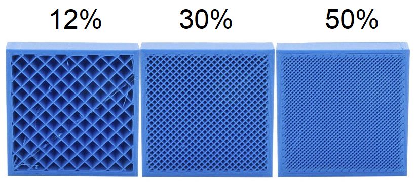
Figure with3 NFRC filaments ranged
is an example from30% an
of 12%,
0.1 mm to 0.4 mm [9,73–75]. Infill refers to the percentage of material to empty space within
A lower
a print. infillinpercentage
Shown Figure 3 is an produces
example of 12%,a hollower
30% and 100%part infills.
as there is more
A lower infill empt
and vice produces
percentage versa. Around
a hollower12%part represents
as there is more the ratio
empty of polymer
space inside and viceto air inside th
versa.
Around 12% represents the ratio of polymer to air inside the part.
infill percentage increases, we can see a lower number of gaps in the part.As the infill percentage
increases, we can see a lower number of gaps in the part.
Figure 3. Infill percentage [84].
Figure 3. Infill percentage [84].
Although there are arguments in the 3D-printing community on the optimum infill
percentage of being there
Although less than 100%,
are i.e., solid print,
arguments a study
in the had shown that
3D-printing better mechani-
community on the o
cal performance was achieved as infill increased up to 100%. Alvarez et al. [85] reported
percentage of being less than 100%, i.e., solid print, a study had show
that specimens printed with a 100% infill had the best impact strength amongst other
mechanical
specimens. performance was achieved as infill increased up to 100%. Alv
Raster that
reported angle specimens
refers to the angle
printed of thewith
direction
a 100%of material
infill being deposited
had the best to the
impact stre
horizontal axis of machine. This angle is usually set by default at 45◦ . Shown in Figure 4
other specimens.
is an illustration of the raster angle, whereby each figure represents a cross section of a
Raster
rectangular angle
printed refers
part. tointhe
As seen angle
Figure 4, a 0of the direction
◦ raster angle settingof material
deposits being de
material
horizontally (left to right) while 90 ◦ angle deposits material vertically (up and down). The
horizontal axis of machine. This angle is usually set by default at 45°. Show
is an illustration of the raster angle, whereby each figure represents a cro
rectangular printed part. As seen in Figure 4, a 0° raster angle setting dep
horizontally (left to right) while 90° angle deposits material vertically (up an
angle was measured between the direction of the printer nozzle (i.e., matermechanical performance was achieved as infill increased up to 100%. Alvarez et al. [85]
reported that specimens printed with a 100% infill had the best impact strength amongst
other specimens.
Raster angle refers to the angle of the direction of material being deposited to the
horizontal axis of machine. This angle is usually set by default at 45°. Shown in Figure 4
Polymers 2021, 13, 2289 12 of 19
is an illustration of the raster angle, whereby each figure represents a cross section of a
rectangular printed part. As seen in Figure 4, a 0° raster angle setting deposits material
horizontally (left to right) while 90° angle deposits material vertically (up and down). The
angle was measured between the direction of the printer nozzle (i.e., material deposited,
and horizontal axis of printer bed plane).
Figure 4.
Figure 4. Schematic
Schematic diagram
diagram of
of raster
raster angle.
angle. Reprinted
Reprinted with
with permission
permission from
from [86].
[86]. Copyright
Copyright 2019
2019 Elsevier.
Elsevier.
Typically,the
Typically, theoptimal
optimal condition
condition would
would be tobe to the
have have the angle
raster rastermatch
anglethematch the
direction
direction
of loading. of However,
loading. However,
this is notthis is notpossible
always always in
possible in practice,
practice, and thusandthe thus
rasterthe raster
angle is
angle isset
always at 45◦set
always toat 45° to average
average out the mechanical
out the mechanical performance.
performance. Fatimatuzahraa
Fatimatuzahraa et
et al. [87]
al. [87] reported
reported that aangle
that a raster ◦
rasterofangle of 45°
45 can can provide
provide superiorsuperior
flexuralflexural strength.
strength.
5. Mechanical Properties of NFRC
Concerning the mechanical properties of 3D-printed materials, the processing pa-
rameter plays a vital role in the determination of the mechanical properties. Processing
parameters of a 3D printer, include the nozzle diameter, extrusion temperature, bed tem-
perature, layer height and printing speed. The mechanical properties of the 3D-printed
materials may change considerably even with one single parameter being modified [88,89].
Besides, the printing temperature is controlled between 200 ◦ C, as most of the polymers
melting temperature is lower than 200 ◦ C. However, the temperature could not be too
high since lignocelluloses in natural fibre tend to degrade at high temperatures, which
could result in negative effects on the mechanical properties. On the other hand, different
properties in natural fibre also influence the overall properties of composites. Therefore, the
selection of natural fibre is also one of the significant factors in producing NFRC with im-
proved mechanical properties, including tensile strength, flexural strength, impact strength,
toughness, durability and hardness. Significant improvements in the mechanical properties
were achieved when reinforcements of natural fibre to pure polymer were reported. Various
reports of natural fibres-reinforced polymer matrix along with their resulting improved
mechanical performance are tabulated in Table 3. Most papers studying the mechanical
performance of bio composites filament for FDM printing dealt with PLA-based and ABS-
based filaments [50,52,57,78,90]. These reported that average tensile strength ranged from
20 up to 40 MPa. With comparison between pure polymer-printed parts and reinforced
ones, it is often concluded that additive of natural fibres could considerably contribute
to tensile strength at specific fibre content [50,52,55,57,78–80,90], while stiffness increases
insignificantly [50,52,55,57,79,80]. Moreover, for composites involving bio-polyethylene or
polypropylene, natural fibres have improved the overall mechanical properties [55,79,80].
However, Gregor-Svetec [81] reported that the addition of cardboard dust to HDPE without
any additive had resulted in inferior mechanical properties for the composites filaments.
Overall, the mechanical properties of the pure polymer can be enhanced by reinforcing withPolymers 2021, 13, 2289 13 of 19
natural fibres at an adequate content. A recent review article by Mazzanti et al. [8] reported
that reinforcement of natural fibre to polymer increased the overall mechanical properties.
However, the mechanical properties of NFRC materials tend to be affected by the
adhesion between the fibre and matrix, whereby poor adhesion could result in mechanical
properties reduction [91]. Therefore, the interfacial adhesion between the natural fibre
and thermoplastic matrix should be improved by modifying them. There are two types
of common methods, which are the addition of coupling agents to matrix materials and
surface treatments of fibre, both chemically. A coupling agent is a compound that provides a
chemical bond between inorganic and organic materials [92]. In general, maleic anhydride-
grafted matrices, such as MAPE used as coupling agents, had proven to improve the tensile
strength of NFRC [93]. Maleic anhydride-grafted polyethylene (MAPE), or malleated
polyethylene, is amongst the most popular chemical coupling agents, specifically for natural
fibre polyethylene composites. It is used to compatibilize the adhesion between natural
fibre and thermoplastic matrix. According to Chen et al. [69], adding the compatibilizer of
MAPE had shown an increase in tensile strength and modulus of up to 35.3% and 16.6%,
respectively, as compared to the NFRC without compatibilizer. Petchwattana et al. [94]
reported that the overall tensile strength and flexural strength increased with the addition
of MAPE between the rice husk and HDPE polymer. Therefore, it showed that using
a coupling agent in natural fibre-reinforced polymer matrix composites is significant in
improving their mechanical performance.
6. Current Optimisation Methods
The parameter settings in the 3D-printing process have a strong effect on the quality
and properties of products, such as mechanical properties and dimension accuracy [95,96].
This implies the importance of optimisation of the parameter settings. To determine the
optimum parameter setting, manufacturers usually have to keep on trying and reject any
errors that occur. This process can be time and cost consuming. Therefore, optimisation is
important in order to produce good quality 3D-printing products with shorter duration and
reduced cost. Response surface methodology (RSM) is a statistical analysis tool that is used
to examine the relation between several experimental variables and response variables.
The basic idea of RSM is to make optimal use of a sequence of designed tests. Through
the optimisation of the operating factors, RSM can be utilised to optimise the production
of a specific substance. The interaction between process variables can be determined by
using statistical techniques, as opposed to conventional methods. The response surface is a
surface placement-based system. Therefore, the key objectives of an RSM analysis are to
recognise and identify the area, whereby most suitable reaction takes place in a topography
of the reaction surface, including the maximum, local, minimum and ridgelines [97].
The RSM examines the correct estimate of input and output variables and defines optimal
operating conditions for the system being studied or for a factor field that meets operational
requirements [98].
A Taguchi method is a descriptive analysis that identifies a product or process so
that its working condition is more reliable. Taguchi method is utilised because it is easy
and simple to enhance procedural factors. The technique is commonly referred to as the
factorial outline of the test. In this method, exhibits called orthogonal arrays (OA) are
designed extraordinarily. The methodology of orthogonal is to choose the level mix of the
factors of the information plan for each trial [99]. The orthogonal array provides a slightly
lower ‘deviation’ to explore a range of ways to ‘ideal setting’ the control parameters. In
Taguchi, the main objective is to optimise the parameter of a process to achieve the best
efficiency. If the quantity of process parameters increases, a lot of analysis must be carried
out to achieve the optimised parameter. The Taguchi method uses the OA to find out
the modest number of tests with the procedure parameter. The OA of Taguchi and the
utilisation of ANOVA can provide the ideal combination of parameters that lead to minimal
defects [100].Polymers 2021, 13, 2289 14 of 19
By selecting the proper process parameters and values, sets of a different combination
by using those values are generated through design of experiment (DOE). At this stage,
different types of DOE can be chosen based on the experimental requirements. The general
types of DOE include Box-Behnken Design and Central Composite Design. The Box-
Behnken model is an independent quadratic design because it does not have a factorial
or fractional design incorporated in it. The treatment combinations of this design are at
the centre and middle ends of the process field. Such designs can be rotated and require
three levels per element. Compared to the central composite designs, these designs have
minimal orthogonal blocking capability. The geometry of this design shows that the
surface of the sphere rises over the surface of the sphere with tangential surface on each
side of the space. A central composite design often requires twice the number of stars
as design factors. After the selection of DOE, different combination sets of the process
parameters are generated by the system. Experiments are conducted for each combination
sets of data to obtain the response variable for them. Those response variables are be
manually entered into the RSM system to determine the optimised parameters for the
3D-printing process. Analysis of variance (ANOVA) and contour plot are carried out after
the determination of the respondent variables. ANOVA is a statistical decision-making
tool that detects differences in average performance and helps test the importance of all
important factors. The ANOVA method is used to understand the percentage contribution
of each parameter. ANOVA is used in experimental design to decompose the total variation
of the experiment into components related to the main effects and interactions, and this
variation is usually called residual. The contour plot generated is used to explore the
effect of a manipulated factor on the response factor. Similarly to RSM, the very first step
to carry out the Taguchi method is to determine the required process parameter for the
experiment and the corresponding value for that process parameter. Once the number of
process parameter is obtained, the number of runs can be determined using the equation.
An OA is created using Minitab with the entered process parameter and levels. After that,
the responding variables are required for the OA for further analysis. Average values for
the responding variables are required for the instance. After obtaining the corresponding
variables for each of the process parameters and levels, it is required to find out the signal-
to-noise (S/N) ratio. In experiments, the signal-to-noise ratio is valuable to identify scaling
factors that are factors with a different mean and standard deviation. Scaling factors
may be used without affecting signal-to-noise ratios to modify the mean on a target. The
Taguchi results are then further analysed by generating the response graph to identify the
impact of the control factor, whereby the parameters that affect the response variable can
be identified as well. RSM is an emphatic approach—a collection, first initiated by Box and
Wilson, for the modelling, problem analysing, modification and optimisation of various
processes in both statistical and mathematical approaches [101]. Meanwhile, Taguchi is a
special statistical method that optimises processes in search of acceptable conditions in the
operating phase. This decreases the number of experiments, and thus produces the least
variation [102]. In a research done by A. E. Tontowi et al., it was stated that as compared
to the Taguchi method, RSM gave a better prediction on the response variable, default
setting of 3D printer and dimension error. A result of the improvement in tensile strength
as the response variable had been obtained, whereby the improvement by using RSM and
Taguchi was 8% and 4%, respectively [103]. In another research done by Yie Hua Tan et al.,
the optimised results with a difference of less than 2% between RSM and Taguchi were
obtained [104]. From the research, it was stated that the prediction of the optimal operating
condition achieved with Taguchi was considered as a limitation as the Taguchi method
requires less experimental information in the analysis and is generally utilised in linear
interactions [105]. Only one optimum value was provided at a specific level. In the Taguchi
method, further experiments are needed to get the future direction of optimum response.
Meanwhile, RSM illustrates the statistical value of all possible interaction combinations
and mathematical models, regarding 95% confidence interval and can help to identify
the direction to optimum response for the future. Moreover, the RSM desirability featureYou can also read