Crescent-shaped electron velocity distribution functions formed at the edges of plasma jets interacting with a tangential discontinuity - ANGEO
←
→
Page content transcription
If your browser does not render page correctly, please read the page content below
Ann. Geophys., 36, 1521–1535, 2018
https://doi.org/10.5194/angeo-36-1521-2018
© Author(s) 2018. This work is distributed under
the Creative Commons Attribution 4.0 License.

Crescent-shaped electron velocity distribution functions formed at
the edges of plasma jets interacting with a tangential discontinuity
Gabriel Voitcu1 and Marius Echim1,2
1 Institute    of Space Science, Magurele, 077125, Romania
2 Belgian     Institute of Space Aeronomy, Brussels, 1180, Belgium

Correspondence: Gabriel Voitcu (gabi@spacescience.ro)

Received: 7 September 2018 – Discussion started: 13 September 2018
Revised: 29 October 2018 – Accepted: 30 October 2018 – Published: 14 November 2018

Abstract. In this paper we discuss numerical simulations             tospheric and geophysical effects (e.g. Plaschke et al., 2009;
that illustrate a physical mechanism leading to the forma-           Hietala et al., 2012, 2018). Dmitriev and Suvorova (2015)
tion of crescent-shaped electron velocity distribution func-         show that > 60 % of the jets detected by the Time His-
tions at the edges of a high-speed plasma jet impacting on           tory of Events and Macroscale Interactions during Substorms
a thin, steep and impenetrable tangential discontinuity with         (THEMIS) mission do penetrate inside the Earth’s magneto-
no magnetic shear. We use three-dimensional particle-in-cell         sphere, while the rest of < 40 % are not able to cross over the
simulations to compute the velocity distribution function of         magnetopause. Some of the penetrating plasmoids were in-
electrons in different areas of the plasma jet and at different      tersected in situ by spacecraft deep inside the magnetosphere
phases of the interaction with the discontinuity. The simu-          (e.g. Lundin and Aparicio, 1982; Woch and Lundin, 1991,
lation set-up corresponds to an idealized, yet relevant, mag-        1992; Yamauchi et al., 1993; Lu et al., 2004; Gunell et al.,
netic configuration likely to be observed at the frontside mag-      2012; Shi et al., 2013; Lyatsky et al., 2016).
netopause under the northward interplanetary magnetic field.            The transport of plasma jets, clouds and blobs across vari-
The combined effect of the gradient-B drift and the remote           ous magnetic field configurations has been investigated with
sensing of large Larmor radius electrons leads to the forma-         magnetohydrodynamic (MHD) (e.g. Ma et al., 1991; Dai
tion of crescent-shaped electron velocity distribution func-         and Woodward, 1994, 1995, 1998; Huba, 1996), hybrid (e.g.
tions. We provide examples of such distributions “measured”          Savoini et al., 1994; Palmroth et al., 2018) and kinetic (e.g.
by a virtual satellite launched into the simulation domain.          Galvez, 1987; Galvez et al., 1988; Livesey and Pritchett,
                                                                     1989; Galvez and Borovsky, 1991; Cai and Buneman, 1992;
                                                                     Neubert et al., 1992; Hurtig et al., 2003; Gunell et al., 2009)
                                                                     numerical simulations (see also the review by Echim and
1   Introduction                                                     Lemaire, 2000). These previous simulations did not reveal
                                                                     all the fundamental aspects of jet dynamics due to the in-
The terrestrial magnetosheath is often populated by high-            herent physical and/or geometrical limitations. For instance,
speed plasma jets (also called plasmoids or plasma irregu-           the MHD and hybrid simulations do not quantify the effect
larities) streaming towards the frontside magnetopause (e.g.         of self-polarization (Schmidt, 1960), which is purely kinetic
Dmitriev and Suvorova, 2012, 2015; Karlsson et al., 2012;            and plays a crucial role for plasma motion across transverse
Gunell et al., 2014) and impact it several times per hour            magnetic fields. On the other hand, the particle-in-cell (PIC)
(Plaschke et al., 2016). These finite-size plasma structures         simulations were limited by the existing computing resources
have an excess of anti-sunward dynamic pressure with re-             and none of them succeeded in evaluating the interaction of a
spect to the ambient magnetosheath (e.g. Hietala et al., 2012;       three-dimensional plasma jet with a tangential discontinuity
Savin et al., 2012; Archer and Horbury, 2013; Plaschke et            (TD). Recently, Voitcu and Echim (2016, 2017) used a 3-
al., 2013, 2017; Karlsson et al., 2018), and their interaction       D PIC code to simulate the dynamics of high-speed plasma
with the magnetopause can trigger local and global magne-

Published by Copernicus Publications on behalf of the European Geosciences Union.
1522 G. Voitcu and M. Echim: Crescent-shaped electron velocity distribution functions
jets interacting with magnetic fields typical for a tangential
discontinuity with no shear. Such a configuration is similar
to the magnetopause under a northward interplanetary mag-
netic field (IMF). It has been shown that the plasma-field in-
teraction process is controlled by the dynamic and kinetic
pressure of the high-speed jet, its electric polarizability and
the magnetic jump at the TD. It was also shown that when
the dynamic pressure is large enough the jet can cross the
TD, as implied by kinetic models like the impulsive pene-
tration mechanism (Lemaire, 1977, 1985; see also Lemaire
and Roth, 1991). When the dynamic pressure is small, the
jet is stopped by the TD, consistent with THEMIS observa-
tions of jets reported by Dmitriev and Suvorova (2015). The
dynamics of finite-size plasma jets and clouds across trans-
verse magnetic fields have been also described with Vlasov
equilibrium solutions by Echim and Lemaire (2005).
In this paper we discuss the kinetic structure of a low-beta
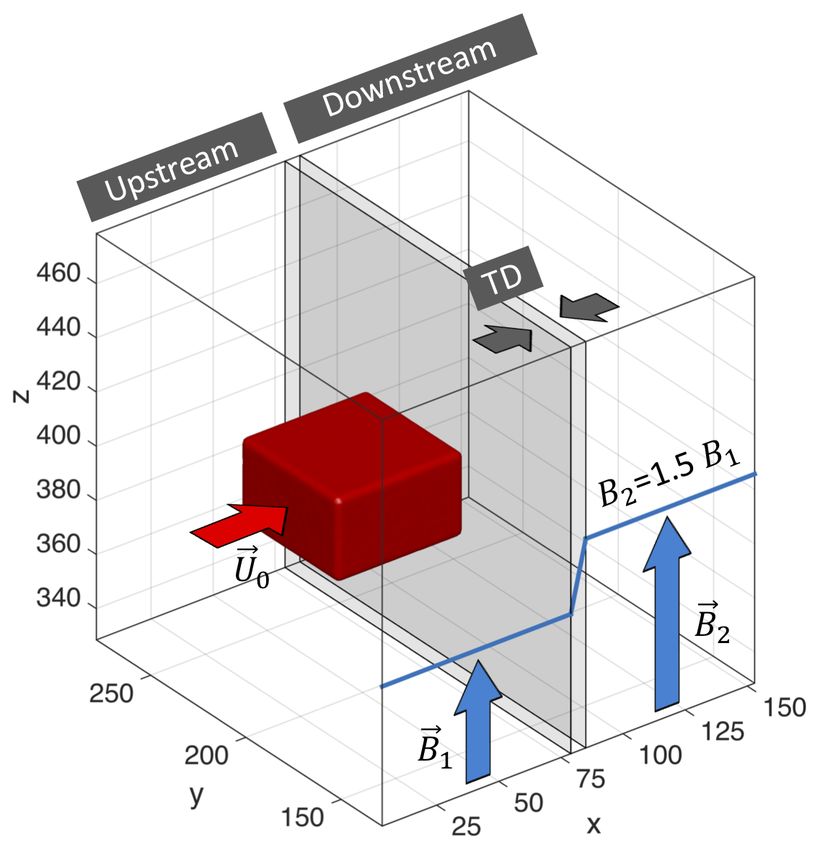
plasma jet impacting on a thin, steep and impenetrable tan- Figure 1. Schematic diagram of the simulation set-up. The high-
gential discontinuity with no magnetic shear. The analysis is speed plasma jet (shown by the red 3-D box) moves from the up-
based on 3-D electromagnetic PIC simulations. We consider stream region towards a parallel tangential discontinuity. The spa-
here an idealized, yet relevant, simulation set-up that corre- tial profile of the background magnetic field is shown in blue. The
tangential discontinuity is located between x1 = 79 and x2 = 85.
sponds to a magnetosheath plasma jet streaming towards the
frontside region of the Earth’s magnetopause and interacting
with it under a northward interplanetary magnetic field. The
netic field; it does not require magnetic reconnection. This
plasma jet has a relatively small momentum and it cannot
paper provides new insight into the kinetic structure of high-
move across the rather steep discontinuity; it is repelled and
speed plasma jets moving in the vicinity of unidirectional
split in two plasma streams moving in opposite directions,
magnetic barriers. We emphasize the role of finite Larmor
tangentially to the TD surface, as discussed in detail in a pre-
radius effects that give rise to crescent-shaped electron dis-
vious publication (Voitcu and Echim, 2017). However, ki-
tributions in the space of perpendicular velocities. Such elec-
netic processes observed during the interaction between the
tron VDFs can indicate the presence of a finite-size plasma
jet and the discontinuity lead to the formation of crescent-
jet deflected tangentially near a parallel magnetic discontinu-
shaped electron velocity distribution functions (VDFs).
ity.
Crescent-like VDFs were observed for ions in the Earth’s
magnetotail, close to the neutral sheet and plasma sheet
boundary layer (e.g. Nakamura et al., 1991, 1992; Wilber 2 Simulation set-up
et al., 2004), as well as in the magnetosheath, close to the
magnetopause (e.g. Marcucci et al., 2004). The crescent- We consider a three-dimensional simulation geometry that
shaped ion VDFs have been associated with various finite allows the simultaneous investigation of plasma convec-
Larmor radius effects (e.g. Lee et al., 2004; Marcucci et al., tion along the injection direction, the electrostatic self-
2004; Voitcu and Echim, 2012; Voitcu et al., 2012). Recently, polarization along the normal to the magnetic field direction
crescent-shaped VDFs were observed by the Magnetospheric and the parallel expansion along the magnetic field lines.
Multiscale (MMS) mission for electrons close to the dayside A schematic overview of the simulation set-up is given in
magnetopause (Burch et al., 2016) and were associated with Fig. 1. The finite-size plasma jet is illustrated by the red 3-
meandering electron orbits near magnetic field reversal in the D box. We envisage the case of small Larmor radius plasma
reconnection sites (Bessho et al., 2016; Lapenta et al., 2017). jets, i.e. the transversal dimension of the localized plasma
Egedal et al. (2016) proposed a two-dimensional theoretical structure is much larger than the ion Larmor radius.
model for the formation of crescent-shaped electron VDFs The background magnetic field is parallel to +Oz every-
in asymmetric magnetic reconnection. The magnetic config- where inside the simulation domain. Its magnitude increases
uration used in our study does not involve the presence of by 50 % between two asymptotic states: B1 (upstream, or
magnetic field reversal regions, as in, for instance, Bessho et left, of TD) and B2 (downstream, or right, of TD). The
al. (2016), Egedal et al. (2016) or Lapenta et al. (2017), since tangential discontinuity is located between x1 = 791x and
we consider a tangential discontinuity with no shear across x2 = 851x (where 1x is the simulation grid spacing). Its
it. The physical mechanism revealed by our PIC simulations width is of the order of few ion Larmor radii, in agreement
leads to crescent-shaped VDFs and is specific to the interac- with theoretical arguments (e.g. Willis, 1978; Roth et al.,
tion between a plasma jet and a parallel non-uniform mag- 1996) and observations (e.g. Cluster measurements, see, for
Ann. Geophys., 36, 1521–1535, 2018 www.ann-geophys.net/36/1521/2018/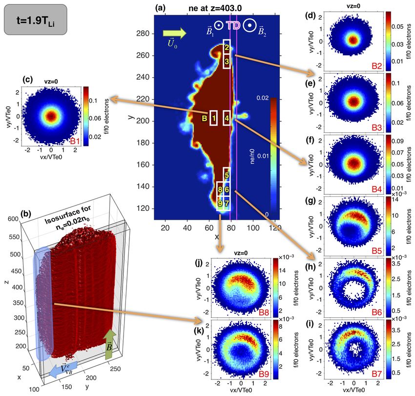
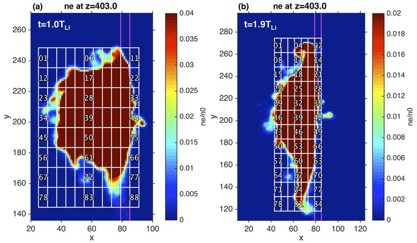
G. Voitcu and M. Echim: Crescent-shaped electron velocity distribution functions                                               1523

instance, Haaland et al., 2004) of the magnetopause thick-          etrable TD discussed in detail by Voitcu and Echim (2016,
ness. Initially, the electric field is set to zero in the entire    2017).
simulation domain. We assume that the background steady-               The PIC code is based on TRISTAN (Buneman, 1993) and
state magnetic field is established prior to the injection of the   has been modified to simulate finite-size plasma structures
plasma jet into the simulation domain and that this configura-      (jets and plasmoids) interacting with non-uniform magnetic
tion remains unchanged during the entire simulation runtime.        fields. The boundary conditions used are periodic for both
The self-consistent magnetic field computed during the sim-         particles and fields. In order to reduce the possible undesired
ulation runtime adds to the background field. Thus, the sim-        effects of boundaries on the plasma dynamics, we keep the
ulated plasma jet can be seen as a perturbation of the equilib-     edges of the simulation domain as far as possible from the
rium solution describing the TD’s magnetic field. Our goal          localized plasma jet. The total number of simulated particles
is to investigate the microphysics of the plasma jet–magnetic       is 30 million for each of the two plasma species, while the
field interaction process in the vicinity of the tangential dis-    number of particles per simulation grid cell at initialization
continuity. The study of TD’s formation and stability is be-        is equal to 400 per species. The proton-to-electron mass ra-
yond the scope of our paper and shall be considered in our          tio is 36. A detailed description of the PIC code is given by
future simulations. Consequently, the background plasma is          Voitcu (2014).
disregarded in the present work and the finite-size plasma jet         The velocity distribution function, f , at different time in-
is streaming in a vacuum towards the magnetic discontinuity,        stances, is computed by using a uniform rectangular grid of
a situation similar to a magnetosheath jet characterized by an      spatial bins that covers the entire plasma jet. For each spa-
excess of dynamic pressure in a rarefied background plasma.         tial bin, we calculate histograms by counting the number of
The kinetic features discussed in the rest of the paper do not      particles, Nt , in each cell of a uniform rectangular grid de-
depend on the properties of the background plasma, but on           fined in the velocity space. Thus, the VDF at time t, for a
the geometry of the jet and the magnetic and electric field         bin of width (δx, δy, δz) in configuration space and a cell of
profile.                                                            width (δvx , δvy , δvz ) in velocity space, is obtained by divid-
   The electrons and protons forming the 3-D plasma jet are         ing Nt to the volume of each 6-D cell in the phase space. The
uniformly distributed over a rectangular region localized at        dimensions of the spatial bins and velocity cells are chosen
the left side of the TD where the magnetic field is uniform.        such that the 6-D phase space is well sampled to provide a
Their initial VDF is a displaced Maxwellian with the av-            good representation of the VDF.
erage velocity parallel to the positive x axis and perpen-             The physical quantities are normalized as follows: the
dicular to the magnetic field direction: U0 = 1.2VTi (where         number density is normalized to its initial value n0 , the par-
VTi is the thermal velocity of protons). The electron-to-ion        ticle velocities are normalized to their initial thermal speed
thermal speed ratio is VTe /VTi = 30. The velocities of both        VT0 = (2kB T0 /m)1/2 . The VDF is normalized to the maxi-
species are initialized according to their corresponding dis-       mum value of the initial displaced Maxwellian distribution,
placed Maxwellian distribution function. Thus, at the begin-        f0 = n0 /(π 3/2 VT30 ). The time and spatial coordinates are nor-
ning of the simulation, the plasma jet is injected into the sim-    malized to the initial ion Larmor period TLi and the grid spac-
ulation domain with an initial bulk velocity pointing towards       ing 1x = 0.5rLe .
the discontinuity surface. The size of the simulation domain
equals 155 × 405 × 805 grid cells, while the initial size of the
plasma jet is 50 × 50 × 30 grid cells.                              3   Numerical results
   The jet’s plasma has a small beta (β = 0.1, including both
dynamic and thermal plasma pressure; βe = 0.09, including           The dynamics of the jet during its interaction with the TD
only electron thermal pressure) and a large dielectric constant     was discussed by Voitcu and Echim (2016, 2017). When the
ε. In the simulations discussed in this paper ε = 500, where        TD is very steep, the jet is repelled and undergoes two dy-
ε = 1+mi n/(ε0 B 2 ) = 1+(ωpi /ωLi )2 is defined as in, for ex-     namical phases: (A) the jet’s frontside interacts directly with
ample, Chen (1974) and Lemaire (1985), with ωpi the ion             the non-uniform magnetic field of the TD, leading to vanish-
plasma frequency and ωLi the ion Larmor frequency. Since            ing of the self-polarization electric field, and (B) the jet is
ε  1, collective dielectric effects play an important role in      repelled and split into two counter-streaming plasma flows
the dynamics of the plasma jet (Schmidt, 1960; Lemaire,             tangential to the TD surface. Here we focus on the kinetic
1985). In this case, a polarization electric field is formed        properties of electrons of the deflected plasma jet and con-
inside the plasma jet that enables its convection across the        sider two instances of its dynamics, typical for phase A (il-
transverse magnetic field (see Voitcu and Echim, 2016, for a        lustrated by Fig. 2) and phase B (illustrated by Fig. 3), re-
detailed discussion on this topic). The ratio between the jet’s     spectively.
transversal dimension and the ion Larmor radius is equal to            We define a uniform grid in configuration space whose
19. The total simulation time covers 4TLi (where TLi is the         cells have the perpendicular size equal to δx = 6 (≈ 3rLe )
Larmor period of protons in the upstream region). This simu-        and δy = 13 (≈ 6rLe ), respectively. This spatial resolution
lation configuration corresponds to the thin, steep and impen-      is chosen in order to achieve a sampling of the numerical

www.ann-geophys.net/36/1521/2018/                                                          Ann. Geophys., 36, 1521–1535, 2018
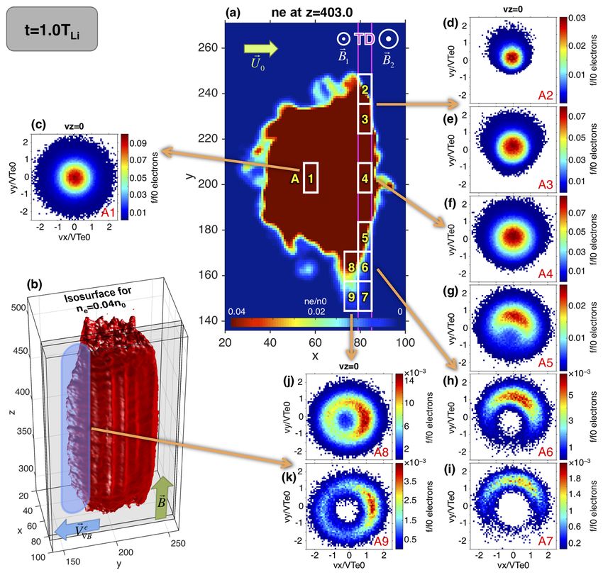
1524                                     G. Voitcu and M. Echim: Crescent-shaped electron velocity distribution functions

Figure 2. Snapshot of 3-D PIC simulation at t = 1TLi (phase A). (a) Electron number density in the xOy plane for z = 403. (b) The 3-D
density isosurface for ne = 0.04n0 . (c–k) Electron VDFs in the space of perpendicular velocities for the spatial bins shown with white
rectangles in panel (a). The two magenta lines mark the TD’s boundaries.

VDFs comparable to the experimental data obtained with a              in Fig. 2 (for t = 1TLi , corresponding to phase A) and Fig. 3
state-of-the-art electron spectrometer in the vicinity of the         (for t = 1.9TLi , corresponding to phase B). In panel (a) we il-
magnetopause, like for example those on MMS whose time                lustrate the number density of electrons for the central cross
resolution is 30 ms. The distance covered by MMS during               section localized in z = 403; panel (b) shows the 3-D shape
30 ms within a plasma flow of 100 km s−1 is of the order              of the plasma jet computed as the isosurface corresponding
of few electron Larmor radii. In order to increase the num-           to ne = 0.04n0 in Fig. 2 and ne = 0.02n0 in Fig. 3. The VDF
ber of particles collected in each bin of the spatial grid, the       is calculated for 88 spatial bins that cover the entire jet at
grid cells are expanded over the entire column of the simu-           t = 1TLi and 84 ones at t = 1.9TLi . We selected the most rel-
lation domain along the z axis (δz = 800). Nevertheless, we           evant nine bins, labelled A1–A9 in Fig. 2a and B1–B9 in
performed tests for smaller δz (not shown) and found that             Fig. 3a. The corresponding electron VDFs are shown in pan-
the relevant features of the VDF do not depend on the cell            els c–k of both Figs. 2 and 3. The VDF maps for the entire
size along Oz. A uniform 3-D grid is also defined in the ve-          spatial grids are provided in Appendix A.
locity space whose cells dimensions are δvz = 0.6VTe0 and                The electron VDF in the core of the plasma jet is a dis-
δvx = δvy = 0.08VTe0 . In the following we discuss sections           placed Maxwellian similar to the initial one, as can be seen
of VDFs in the plane perpendicular to the magnetic field              in Figs. 2c and 3c. However, the VDFs at the boundaries of
obtained from velocity cells whose centres are located in             the deflected plasma jet are non-gyrotropic, as shown by bins
vz = 0.                                                               A5–A9 and B5–B9, where the phase-space density is virtu-
   The numerical simulations results obtained for the inter-          ally empty in the central region, for small perpendicular ve-
action of the high-speed plasma jet with the TD are shown             locities. The VDF takes, however, larger values in the sector

Ann. Geophys., 36, 1521–1535, 2018                                                           www.ann-geophys.net/36/1521/2018/
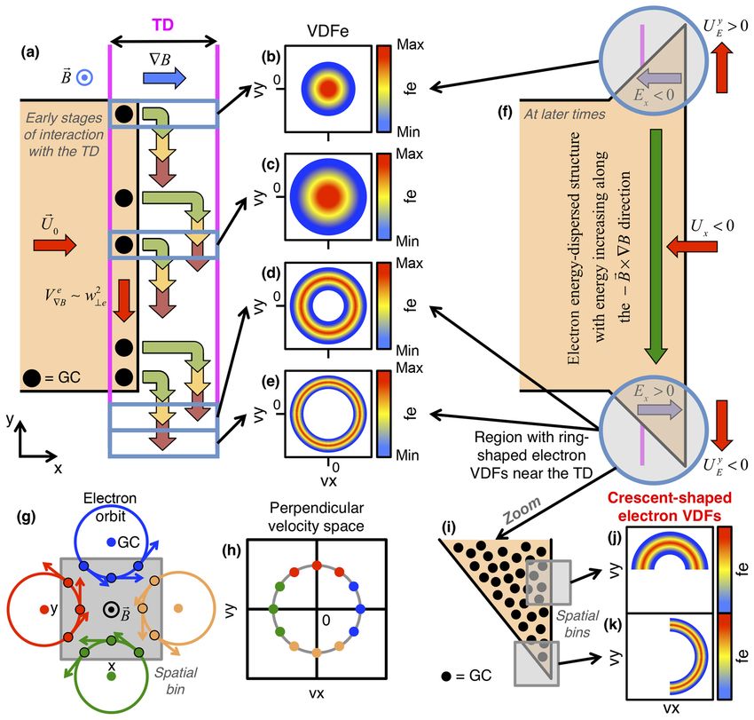
G. Voitcu and M. Echim: Crescent-shaped electron velocity distribution functions                                                   1525

Figure 3. Snapshot of 3-D PIC simulation at t = 1.9TLi (phase B). (a) Electron number density in the xOy plane for z = 403. (b) The 3-
D density isosurface for ne = 0.02n0 . (c–k) Electron VDFs in the space of perpendicular velocities for the spatial bins shown with white
rectangles in panel (a). The two magenta lines mark the TD’s boundaries.

of a ring around the depleted core. These features give the            interact with the magnetic field gradient inside the discon-
VDF a crescent-like aspect. On the other hand, the VDFs in             tinuity and drift in the – Oy direction with a velocity propor-
the frontal bins A2, A3, B2 and B3 are depleted at larger ve-          tional to their gyration energy (Northrop, 1963). Thus, the
locities, while the phase-space density for small velocities is        electrons with higher kinetic energies are scattered to larger
large.                                                                 distances than the less energetic ones. The forward motion of
   These non-gyrotropic features of the VDFs are observed              the jet towards the discontinuity continuously replenish the
in the plane of perpendicular velocities, inside the TD (bins          electron population at the front edge. The gradient-B drift
A5–A7), but also outside it (bins A8, A9 and B5–B9). Their             acts as a filter of the perpendicular velocities whose effect is
characteristics change with the distance from the jet bound-           the formation of an energy-dispersed structure in the frontal
aries. On the one hand, the size of the VDF’s central cavity           region of the plasma jet; the electrons with higher kinetic en-
increases towards the lateral edge of the jet (compare, for in-        ergies accumulate towards the jet’s lateral edge, in the direc-
stance, the VDFs plotted for bins A6 and A7). On the other             tion −B × ∇B (compare, for instance, Fig. 4b and e). Due to
hand, the VDFs take non-vanishing values only in limited               this filtering effect, the regions far from the centre of the jet,
sectors surrounding the central cavity; the peak VDF density           along – Oy, cannot be reached by the low-energy electrons
in the ring varies from one bin to another (compare, for in-           whose gradient-B drift velocity is small. Thus, far from the
stance, the VDFs for bins A6 and A8 in Fig. 2).                        jet’s centre, the phase space of small velocities is empty and a
   The physical mechanisms contributing to the formation               central cavity is formed, as shown in Fig. 4d and e. The VDF
of crescent-shaped electron VDFs are illustrated by the di-            is therefore ring-shaped. The corresponding low-energy cut-
agrams in Fig. 4. The electrons in the frontside of the jet            off of the phase-space ring increases with the distance from

www.ann-geophys.net/36/1521/2018/                                                              Ann. Geophys., 36, 1521–1535, 2018
1526                                         G. Voitcu and M. Echim: Crescent-shaped electron velocity distribution functions

Figure 4. Panel (a) illustrates the phase A of plasma jet’s interaction with the magnetic discontinuity. The black dots indicate the guiding
centres (GCs) of electrons localized at the front edge. The multiple groups of green–yellow–red arrows show the gradient-B drift displacement
of the GCs proportional to the gyration energy (green corresponds to the lowest energy). The four blue boxes indicate the bins where the VDF
is computed. The electron VDFs obtained for the upper edge bins (b, c) are gyrotropic and their phase density vanishes for large velocities;
the VDFs obtained for the bottom edge bins (d, e) are ring-shaped. Panels (g) and (h) illustrate how the electrons with GCs outside a spatial
bin contribute to different sectors of the VDF collected in the respective bin. The colours of the dots in panel (h) identify which particle shown
in panel (g) contributes to that sector of the VDF. This effect corresponds to a remote sensing of the large Larmor radius electrons outside
the bin. Panels (f) and (i)–(k) show how the remote sensing effect contributes to the formation of crescent-shaped VDFs in a configuration
similar to the PIC simulations.

the jet’s centre along – Oy, since the spatial regions increas-            when the plasma drifts far from the actual interaction with the
ingly farther from the central region of the jet are accessi-              non-uniform field. The tangential deflection of the jet carries
ble to electrons with increasingly larger gyration velocities              the energy-dispersed structure away from the impact zone
(compare the VDF’s central cavities in Fig. 4d and e). Fig-                and enhances the asymmetry of the lateral edges. The low-
ure 2 and the diagrams in Fig. 4a–e show the formation of                  energy electrons and the ring-shaped VDFs are displaced in
ring-shaped VDFs during phase A of the interaction between                 opposite directions, to larger and larger distances from the
the jet and the TD.                                                        core. The diagram in Fig. 4f illustrates this effect. Note that
   Nevertheless, the kinetic features imprinted by the                     this mechanism partially explains the simulation results, but
gradient-B drift during phase A are persistent and the non-                it does not account for the non-gyrotropy. To clarify this is-
Maxwellian electron VDFs are observed later in the simu-                   sue, we must consider a supplemental effect.
lation when the jet is pushed back, outside the TD. Indeed,                   Let us discuss the VDFs obtained in spatial bins A5–A9
during the backward convection of jet’s frontal regions, the               and B5–B9 from Figs. 2 and 3, respectively. The diagram in
energy-dispersed structure is displaced in the – Ox direction.             Fig. 4g illustrates such a rectangular bin, as well as the guid-
This explains the shape of VDFs in spatial bins localized in               ing centres of four electron orbits localized outside the bin’s
regions of uniform magnetic field, like A8 and A9 in Fig. 2                boundaries, whose Larmor radii are comparable to the size
and B5–B9 in Fig. 3. Thus, the ring-shaped VDFs persist                    of the bin. Each orbit intersects the area of the bin for a lim-

Ann. Geophys., 36, 1521–1535, 2018                                                                   www.ann-geophys.net/36/1521/2018/
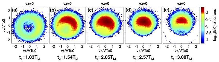
G. Voitcu and M. Echim: Crescent-shaped electron velocity distribution functions                                               1527

ited time interval and is counted when computing the VDF            ing of large Larmor radius electrons at the lateral edge of
value in the velocity space region determined by the electron       the jet – this effect explains why certain regions of the ring-
gyration velocity along the segment of the orbit inside the         shaped VDFs have very small phase density, leading to the
bin. That region in the velocity space changes for each of the      crescent-like shape. The simulations also show that the ki-
four illustrative orbits considered in Fig. 4g according to the     netic structure resulting from the interaction with the discon-
gyration phase. For instance, within the segment localized in       tinuity is maintained at later stages, when the jet is deflected
the bin, the gyration velocity of the electron following the red    and pushed outside the TD. Indeed, the non-gyrotropic fea-
orbit takes values that are restricted to the upper sector of the   tures imprinted by the interaction of the low-beta plasma jet
perpendicular velocity space where vy > 0, while the gyra-          with the steep tangential discontinuity are observed during its
tion velocity of the electron along the blue orbit is restricted    subsequent motion. In the case of high-beta plasma jets, we
to the vx > 0 sector, as shown in Fig. 4h. The absence of cer-      expect that the dynamics of the electrons and ions to be af-
tain guiding centres (and of their intersecting orbits) around      fected by the magnetic perturbation produced by the jet itself
the spatial bin decreases the VDF’s phase density for the ve-       and, consequently, to alter the velocity filtering and remote
locities corresponding to the missing guiding centres. Thus,        sensing effects, leading to the formation of crescent-shaped
the spatial inhomogeneity at the borders of the jet manifests       electron VDFs. Supplemental simulations are envisaged in
as phase-space non-gyrotropy of the distribution function.          the future to clarify this aspect. It should be mentioned that
This effect leads to the formation of non-gyrotropic VDFs           the ion VDFs (not discussed here) do not show any crescent
in the spatial bin itself and is noticeable in regions of config-   features in the perpendicular velocity space.
uration space characterized by sharp variations in the density         Numerous recent spacecraft observations show the om-
of particles with large kinetic energy.                             nipresence of magnetosheath jets and therefore there is an
   The mechanism discussed above can be verified for a con-         increased interest in their kinetic structure (see for exam-
figuration similar to our numerical simulations. For this pur-      ple Plaschke et al., 2017; Karlsson et al., 2018). Below we
pose, a schematic diagram is sketched in Fig. 4i, where we          discuss a possible method to check the results of our sim-
consider two spatial bins close to the jet’s boundaries. We         ulations against spacecraft observations. For this purpose,
discuss the VDFs collected in these two bins. The distribu-         we “launched” a virtual satellite into the simulation domain.
tion of the guiding centres around the bins is non-uniform.         The VDF is “measured” by counting the particles local-
Indeed, the top bin in Fig. 4i is predominantly intersected by      ized within a fixed spatial bin centred on the virtual satel-
large Larmor radius orbits whose guiding centres are found          lite. We use the same spatial resolution as in Figs. 2 and 3,
at the left side (like the red orbit in Fig. 4g), while the bot-    and thus the resolution of the virtual satellite measurements
tom bin is mostly crossed by orbits from above (similarly to        is comparable to the very high-resolution electron measure-
the blue orbit in Fig. 4g). Therefore, the phase-space density      ments provided by MMS. In Fig. 5 we show five examples
of the VDF in the two spatial bins is non-vanishing only in         of electron VDFs measured by the virtual satellite. For con-
a limited sector defined by vy > 0 (the top bin) and vx > 0         sistency, we consider the same satellite S1 as in Voitcu and
(the bottom bin), respectively. Thus, only the upper (right)        Echim (2017). A virtual time series of VDFs is collected at
part of the ring-shaped VDF in Fig. 4d (Fig. 4e) is accessi-        x = 75, y = 153 and z = 403, at t1 = 1.03TLi , t2 = 1.54TLi ,
ble to the top (bottom) bin and the VDFs in these regions           t3 = 2.05TLi , t4 = 2.57TLi and t5 = 3.08TLi . We illustrate the
are crescent-shaped, as illustrated in Fig. 4j and k. This ex-      perpendicular cross sections corresponding to vz = 0 and use
plains the results of our simulations. Indeed, if one checks the    the same resolution in velocity space as in Figs. 2 and 3.
electron VDFs from the numerical simulations in Fig. 2, one         The temporal separation of the five VDFs is equal to 19TLe
notes the crescent-like features in bins A6 and A8 in Fig. 2a       (where TLe is the Larmor period of electrons in the upstream
similar to the top and bottom bins in Fig. 4i (compare the          region); it corresponds to a 30 ms time resolution, which is
VDFs in Fig. 2h and j to the ones in Fig. 4j and k). On the         compatible with the MMS measurements of electron VDFs
other hand, bin B5 in Fig. 3a is crossed by orbits that have        in a magnetic field of 23 nT.
the guiding centres localized at its left side and also above it.      The virtual satellite probes the jet’s lateral edge, deflected
The crescent-shaped VDF in this case is rotated towards the         towards the −B × ∇B direction in the vicinity of the TD
(vx > 0, vy > 0) sector of the perpendicular velocity space,        (which could correspond to an idealized magnetopause). It
as can be seen in Fig. 3g. Similar arguments explain the ori-       moves within the energy-dispersed structure and detects the
entation of all crescent-shaped VDFs in Figs. 2 and 3.              crescent-shaped electron VDFs illustrated in Fig. 5a–e. The
   The discussion above shows that the formation of crescent-       morphology and orientation of the electron VDFs change in
like electron VDFs at the edges of a low-beta plasma jet in-        time. At t1 = 1.03TLi (see Fig. 5a), the crescent is thinner and
teracting with a magnetic discontinuity is the result of a com-     the phase density is enhanced in the vx > 0 sector of the per-
bined effect due to (i) the formation of an energy dispersion       pendicular velocity space (as in Fig. 2k). Up to t5 = 3.08TLi
region at the front edge of the plasma jet sustained by the         (see Fig. 5e), the crescent becomes thicker and thicker and
energy-dependent gradient-B drift – this effect leads to the        it rotates counter clockwise towards the vy > 0 sector, as
formation of a ring shaped VDF – and (ii) the remote sens-          the virtual satellite samples different areas close to the jet’s

www.ann-geophys.net/36/1521/2018/                                                          Ann. Geophys., 36, 1521–1535, 2018
1528                                       G. Voitcu and M. Echim: Crescent-shaped electron velocity distribution functions

Figure 5. Virtual time series of five electron VDFs “measured” by a virtual satellite launched into the simulation domain. We illustrate the
space of perpendicular velocities for vz = 0. The colour scale used is logarithmic.

boundaries. In a frame of reference attached to the deflected             1. The crescent-shaped electron VDFs are observed in a
plasma jet, the satellite is moving away from the jet’s edge                 magnetic field configuration that has no X line. Their
at the lowest y value, drifting along the positive direction of              occurrence and characteristics depend on the dynamic
the y axis and at the same time closer to the TD’s surface.                  and geometric properties of the jet, as well as on the
Indeed, at time t1 , the area sampled by the virtual satellite               profile of the non-uniform magnetic and electric fields
is similar to that of bin A9 in Fig. 2a, while at time t5 the                at the discontinuity.
satellite is in a similar position to the centre of the bin A5 in
Fig. 2a. Thus, the position of the satellite changes with re-             2. The energy-dependent gradient-B drift of the electrons
spect to the plasma jet’s core. At time t1 , the satellite is at             in the frontside of the jet leads to the formation of
its farthest distance from the jet’s core along the −B × ∇B                  an energy-dispersed structure with ring-shaped velocity
direction and the corresponding VDF has the largest central                  distribution functions: the electrons with higher gyra-
cavity in the space of perpendicular velocities. Later on, the               tion energies accumulate towards the jet’s lateral edge
satellite moves closer to the jet’s core and the size of the                 along the −B × ∇B direction, where the VDF shows a
VDF’s central cavity decreases. The position of the satellite                deficit of low energy electrons in the perpendicular ve-
also changes with respect to the local orientation of the jet’s              locity space.
boundaries. While at time t1 most of the electrons are com-
ing from above the satellite’s sampling area (like the blue               3. Within the most lateral edges of the energy-dispersed
orbit in Fig. 4g), at t5 most of them are coming from the left               structure, the ring of the VDF is incomplete and the
side (like the red orbit in Fig. 4g). Consequently, the peak of              VDF’s shape changes from ring-shaped to crescent-
the gyrophase density in the space of perpendicular velocities               shaped. The crescent is due to the spatial anisotropy
rotates from the vx > 0 sector in Fig. 5a towards the vy > 0                 at the sharp edges of the plasma jet. It is produced by
sector in Fig. 5e. Since the properties of the measured elec-                the remote sensing of high-energy particles whose guid-
tron VDFs depend on the relative location of the satellite with              ing centres are localized inside the jet, as illustrated
respect to the jet’s core and boundaries, such velocity distri-              schematically in Fig. 4.
bution functions could be used to estimate some geometrical
and morphological features of a deflected plasma jet.                     4. The crescent-shaped VDFs are produced simultane-
                                                                             ously by (i) the velocity filtering effect of the gradient-B
                                                                             drift and (ii) the remote sensing of large Larmor radius
4   Summary and conclusions                                                  electrons at the boundaries of the plasma jet.
Three-dimensional PIC simulations of the interaction be-                  5. Virtual time series of electron VDFs recorded by a vir-
tween a low-beta plasma jet and a thin, steep and impenetra-                 tual satellite launched into the simulation domain show
ble tangential discontinuity with no magnetic shear empha-                   that the ring-shaped and crescent-shaped electron VDFs
size the formation of crescent-shaped electron velocity distri-              are persistent and carried by the jet during its motion
bution functions at the jet’s boundaries. The simulation set-                after interacting with the magnetic discontinuity. Their
up corresponds to an idealized, yet relevant, magnetic config-               properties (like the size and position of the crescent)
uration likely to be observed at the frontside magnetopause                  change with the satellite’s location within the jet, and
during northward IMF. The results of our simulations show                    thus such VDFs can help to estimate the geometrical
the following:                                                               and morphological features of a deflected jet during or
                                                                             after its interaction with a tangential discontinuity or re-
                                                                             gions of sharp magnetic field variation.

Ann. Geophys., 36, 1521–1535, 2018                                                               www.ann-geophys.net/36/1521/2018/
G. Voitcu and M. Echim: Crescent-shaped electron velocity distribution functions 1529 The new and original result of our study is the identification rection. On the other hand, in Bessho et al. (2016), Burch of crescent-shaped electron VDFs as a boundary effect at the et al. (2016), Egedal et al. (2016), Shay et al. (2016) and edges of a finite-size three-dimensional plasma jet impacting Lapenta et al. (2017) for example, the electron crescents are on a tangential discontinuity with no field reversal. The prop- obtained in connection to the anti-parallel jetting along the erties of the crescents vary with the distance from the jet’s magnetospheric field direction produced by magnetic recon- centre in the −B × ∇B direction; they also depend on the nection; the corresponding VDFs are found close to the mag- local orientation of the jet’s boundaries. The physical mech- netic null region. Egedal et al. (2016) show that the crescent- anism we propose to explain the crescent-shaped VDFs is shaped electron VDFs are formed along the low-density sep- based on finite Larmor radius effects. To our knowledge, this aratrix in a thin boundary layer with the width of approxi- is for the first time that such electron velocity distributions mately one electron Larmor radius. In our simulations, the have been emphasized in the absence of X lines and mag- crescent-shaped electron VDFs are observed over a wide netic field reversal, and the physical process proposed adds area, covering a few tens of electron Larmor radii in the per- to the ones discussed in the past like, for instance, the remote pendicular plane to the magnetic field. sensing of a thin Harris sheet (Lee et al., 2004; Voitcu and The simulations discussed in this paper provide new in- Echim, 2012), the dynamics of non-magnetized Speiser-like sight into the microphysics of plasma-field interaction near electrons (Bessho et al., 2016; Shay et al., 2016; Lapenta et magnetic boundaries and contribute to advancing the un- al., 2017) or the dynamics of magnetized electrons (Egedal derstanding of the dynamics and kinetics of magnetosheath et al., 2016) in the diffusion region of magnetic reconnection high-speed jets streaming towards the magnetopause during sites. periods of northward IMF. We also demonstrate that the cres- The crescent-shaped electron VDFs discussed in this paper cent is a persistent feature of the VDFs that can be detected and the ones reported in connection with magnetic reconnec- at relatively large distances from the interaction with the dis- tion at the dayside magnetopause show similar features in continuity and therefore might be used as the kinetic signa- the perpendicular velocity space, but there are also signifi- ture of such an interaction. cant differences between them related to the actual geome- try of the physical processes leading to their formation. In our simulations, the electron crescents are obtained in con- Data availability. The simulation data used to produce all the plots nection to a counter-streaming jetting structure in the per- and analyses included in this paper can be requested by sending pendicular direction to both the background magnetic field an e-mail to Gabriel Voitcu at one of the following addresses: and the normal to the TD’s surface (our simplified magne- gabi@spacescience.ro or gabriel.voitcu@gmail.com. topause) and involve velocity filtering and remote sensing effects; the corresponding VDFs are found inside and also in the vicinity of the discontinuity towards the −B × ∇B di- www.ann-geophys.net/36/1521/2018/ Ann. Geophys., 36, 1521–1535, 2018
1530 G. Voitcu and M. Echim: Crescent-shaped electron velocity distribution functions
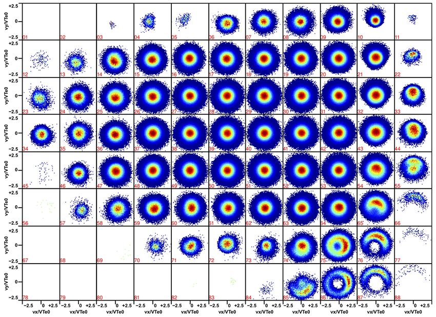
Appendix A t = 1TLi ) and A3 (at t = 1.9TLi ) where we show cross sec-
tions corresponding to vz = 0. The nine selected bins A1–A9
We present here the full map of the electron velocity distribu- in Fig. 2 of the article correspond to bins 39, 10, 21, 43, 65,
tion functions for all the spatial bins defined in the xOy plane, 76, 87, 75 and 86 in Fig. A1a. The nine selected bins B1–B9
perpendicular to the magnetic field direction. In Fig. A1 in Fig. 3 of the article correspond to bins 39, 6, 13, 41, 69, 76,
we show the electron number density in the plane xOy for 83, 75 and 82 in Fig. A1b. One note that in the bulk of the jet
z = 403, at two instances, (a) t = 1TLi and (b) t = 1.9TLi , to- the VDF is a displaced Maxwellian, consistent with the for-
gether with all the bins used to calculate the electron VDFs. ward motion of the plasma. The non-gyrotropic effects are
There are 88 bins in Fig. A1a and 84 bins in Fig. A1b that localized at the edges of the plasma jet.
cover the entire plasma jet at the two different time instances.
The VDFs for each spatial bin are illustrated in Figs. A2 (at
Figure A1. Electron number density for the z = 403 cross section together with the entire spatial grid used to calculate the electron velocity
distribution functions, at (a) t = 1TLi and (b) t = 1.9TLi . There are 88 spatial bins in panel (a) and 84 in (b).
Ann. Geophys., 36, 1521–1535, 2018 www.ann-geophys.net/36/1521/2018/G. Voitcu and M. Echim: Crescent-shaped electron velocity distribution functions 1531 Figure A2. Electron VDFs, at t = 1TLi , for each of the 88 spatial bins defined in Fig. A1a. We show vz = 0 cross sections. The nine VDFs presented in Fig. 2 of the article correspond to bins 39, 10, 21, 43, 65, 76, 87, 75 and 86. www.ann-geophys.net/36/1521/2018/ Ann. Geophys., 36, 1521–1535, 2018
1532                                       G. Voitcu and M. Echim: Crescent-shaped electron velocity distribution functions

Figure A3. Electron VDFs, at t = 1.9TLi , for each of the 84 spatial bins defined in Fig. A1b. We show vz = 0 cross sections. The nine VDFs
presented in Fig. 3 of the article correspond to bins 39, 6, 13, 41, 69, 76, 83, 75 and 82.

Ann. Geophys., 36, 1521–1535, 2018                                                              www.ann-geophys.net/36/1521/2018/
G. Voitcu and M. Echim: Crescent-shaped electron velocity distribution functions                                                      1533

Author contributions. GV: conceptualization, methodology, soft-           Dai, W. and Woodward, P. R.: Two-dimensional simulations for the
ware, formal analysis, investigation, visualization, writing – original     impulsive penetration of a solar wind filament into the magneto-
draft and review and editing. ME: conceptualization, methodology,           sphere, J. Geophys. Res., 99, 8577–8584, 1994.
investigation, supervision, visualization, writing – original draft and   Dai, W. and Woodward, P. R.: Interactions between a solar wind
review and editing.                                                         filament and an open magnetosphere, J. Geophys. Res., 100,
                                                                            14843–14852, 1995.
                                                                          Dai, W. and Woodward, P. R.: Oblique penetration of solar-wind
Competing interests. The authors declare that they have no conflict         filaments into the magnetosphere, J. Plasma Phys., 60, 711–729,
of interest.                                                                1998.
                                                                          Dmitriev, A. V. and Suvorova, A. V.: Traveling magnetopause
                                                                            distortion related to a large-scale magnetosheath plasma jet:
Acknowledgements. The authors acknowledge support from the                  THEMIS and ground-based observations, J. Geophys. Res., 117,
Romanian Space Agency (ROSA) through the Space Technology                   A08217, https://doi.org/10.1029/2011JA016861, 2012.
and Advanced Research (STAR) Programme under contracts                    Dmitriev, A. V. and Suvorova, A. V.: Large-scale jets in the mag-
182/2017 (OANA) and 122/2017 (ODYN) and also from the                       netosheath and plasma penetration across the magnetopause:
Romanian Executive Agency for Higher Education, Research,                   THEMIS observations, J. Geophys. Res.-Space, 120, 4423–
Development and Innovation Funding (UEFISCDI) through                       4437, https://doi.org/10.1002/2014JA020953, 2015.
project VESS/2018. Marius Echim acknowledges support from the             Echim, M. M. and Lemaire, J. F.: Laboratory and numerical simu-
Belgian Solar-Terrestrial Centre of Excellence (STCE) in Brussels,          lations of the impulsive penetration mechanism, Space Sci. Rev.,
Belgium.                                                                    92, 565–601, 2000.
                                                                          Echim, M. M. and Lemaire, J.: Two-dimensional Vlasov solution
Edited by: Elias Roussos                                                    for a collisionless plasma jet across transverse magnetic field
Reviewed by: two anonymous referees                                         lines with a sheared bulk velocity, Phys. Rev. E, 72, 036405,
                                                                            https://doi.org/10.1103/PhysRevE.72.036405, 2005.
                                                                          Egedal, J., Le, A., Daughton, W., Wetherton, B., Cassak, P. A.,
                                                                            Chen, L.-J., Lavraud, B., Torbert, R. B., Dorelli, J., Gershman,
                                                                            D. J., and Avanov, L. A.: Spacecraft Observations and Ana-
References                                                                  lytic Theory of Crescent-Shaped Electron Distributions in Asym-
                                                                            metric Magnetic Reconnection, Phys. Rev. Lett., 117, 185101,
Archer, M. O. and Horbury, T. S.: Magnetosheath dynamic pres-               https://doi.org/10.1103/PhysRevLett.117.185101, 2016.
  sure enhancements: occurrence and typical properties, Ann. Geo-         Galvez, M.: Computer simulation of a plasma streaming across a
  phys., 31, 319–331, https://doi.org/10.5194/angeo-31-319-2013,            magnetic field, Phys. Fluids, 30, 2729–2739, 1987.
  2013.                                                                   Galvez, M. and Borovsky, J. E.: The expansion of polarization
Bessho, N., Chen, L.-J., and Hesse, M.: Electron distribu-                  charge layers into a magnetized vacuum: theory and computer
  tion functions in the diffusion region of asymmetric mag-                 simulations, Phys. Fluids B-Plasma, 3, 1892–1907, 1991.
  netic reconnection, Geophys. Res. Lett., 43, 1828–1836,                 Galvez, M., Gary, S. P., Barnes, C., and Winske, D.: Computer sim-
  https://doi.org/10.1002/2016GL067886, 2016.                               ulations of plasma expansion across a magnetic field, Phys. Flu-
Buneman, O.: TRISTAN – The 3D electromagnetic particle code,                ids, 31, 1554–1567, 1988.
  in: Computer Space Plasma Physics: Simulation Techniques and            Gunell, H., Walker, J. J., Koepke, M. E., Hurtig, T., Brenning,
  Software, edited by: Matsumoto, H. and Omura, Y., Terra Scien-            N., and Nilsson, H.: Numerical experiments on plasmoids en-
  tific Publishing Company, Tokyo, 1993.                                    tering a transverse magnetic field, Phys. Plasmas, 16, 112901,
Burch, J. L., Torbert, R. B., Phan, T. D., Chen, L.-J., Moore, T.           https://doi.org/10.1063/1.3267860, 2009.
  E., Ergun, R. E., Eastwood, J. P., Gershman, D. J., Cassak, P.          Gunell, H., Nilsson, H., Stenberg, G., Hamrin, M., Karlsson, T.,
  A., Argall, M. R., Wang, S., Hesse, M., Pollock, C. J., Giles,            Maggiolo, R., André, M., Lundin, R., and Dandouras, I.: Plasma
  B. L., Nakamura, R., Mauk, B. H., Fuselier, S. A., Russell, C.            penetration of the dayside magnetopause, Phys. Plasmas, 19,
  T., Strangeway, R. J., Drake, J. F., Shay, M. A., Khotyaintsev,           072906, https://doi.org/10.1063/1.4739446, 2012.
  Yu. V., Lindqvist, P.-A., Marklund, G., Wilder, F. D., Young,           Gunell, H., Stenberg Wieser, G., Mella, M., Maggiolo, R., Nilsson,
  D. T., Torkar, K., Goldstein, J., Dorelli, J. C., Avanov, L. A.,          H., Darrouzet, F., Hamrin, M., Karlsson, T., Brenning, N., De
  Oka, M., Baker, D. N., Jaynes, A. N., Goodrich, K. A., Co-                Keyser, J., André, M., and Dandouras, I.: Waves in high-speed
  hen, I. J., Turner, D. L., Fennell, J. F., Blake, J. B., Clemmons,        plasmoids in the magnetosheath and at the magnetopause, Ann.
  J., Goldman, M., Newman, D., Petrinec, S. M., Trattner, K. J.,            Geophys., 32, 991–1009, https://doi.org/10.5194/angeo-32-991-
  Lavraud, B., Reiff, P. H., Baumjohann, W., Magnes, W., Steller,           2014, 2014.
  M., Lewis, W., Saito, Y., Coffey, V., and Chandler, M.: Electron-       Haaland, S. E., Sonnerup, B. U. Ö., Dunlop, M. W., Balogh, A.,
  scale measurements of magnetic reconnection in space, Science,            Georgescu, E., Hasegawa, H., Klecker, B., Paschmann, G., Puhl-
  352, 2939, https://doi.org/10.1126/science.aaf2939, 2016.                 Quinn, P., Rème, H., Vaith, H., and Vaivads, A.: Four-spacecraft
Cai, D. S. and Buneman, O.: Formation and stability of polarization         determination of magnetopause orientation, motion and thick-
  sheaths of a cross-field beam, Phys. Fluids B-Plasma, 4, 1033–            ness: comparison with results from single-spacecraft methods,
  1046, 1992.                                                               Ann. Geophys., 22, 1347–1365, https://doi.org/10.5194/angeo-
Chen, F. F.: Introduction to plasma physics and controlled fusion,          22-1347-2004, 2004.
  2nd Edn., Plenum Press, New York, 1974.

www.ann-geophys.net/36/1521/2018/                                                                 Ann. Geophys., 36, 1521–1535, 2018
1534 G. Voitcu and M. Echim: Crescent-shaped electron velocity distribution functions Hietala, H., Partamies, N., Laitinen, T. V., Clausen, L. B. N., Facskó, Lyatsky, W., Pollock, C., Goldstein, M. L., Lyatskaya, S., G., Vaivads, A., Koskinen, H. E. J., Dandouras, I., Rème, H., and and Avanov, L.: Penetration of magnetosheath plasma Lucek, E. A.: Supermagnetosonic subsolar magnetosheath jets into dayside magnetosphere: 1. Density, velocity, and and their effects: from the solar wind to the ionospheric convec- rotation, J. Geophys. Res.-Space, 121, 7699–7712, tion, Ann. Geophys., 30, 33–48, https://doi.org/10.5194/angeo- https://doi.org/10.1002/2015JA022119, 2016. 30-33-2012, 2012. Ma, Z. V., Hawkins, J. G., and Lee, L. C.: A simulation study of Hietala, H., Phan, T. D., Angelopoulos, V., Oieroset, M., Archer, impulsive penetration of solar wind irregularities into the mag- M. O., Karlsson, T., and Plaschke, F.: In situ observa- netosphere at the dayside magnetopause, J. Geophys. Res., 96, tions of a magnetosheath high-speed jet triggering magne- 15751–15765, 1991. topause reconnection, Geophys. Res. Lett., 45, 1732–1740, Marcucci, M. F., Bavassano Cattaneo, M. B., Pallocchia, G., Am- https://doi.org/10.1002/2017GL076525, 2018. ata, E., Bruno, R., Di Lellis, A. M., Formisano, V., Rème, H., Huba, J. D.: Impulsive plasmoid penetration of a tangential disconti- Bosqued, J. M., Dandouras, I., Sauvaud, J.-A., Kistler, L. M., nuity: Two-dimensional ideal and Hall magnetohydrodynamics, Moebius, E., Klecker, B., Carlson, C. W., Parks, G. K., Mc- J. Geophys. Res., 101, 24855–24868, 1996. Carthy, M., Korth, A., Lundin, R., and Balogh, A.: Energetic Hurtig, T., Brenning, N., and Raadu, M. A.: Three-dimensional magnetospheric oxygen in the magnetosheath and its response electrostatic particle-in-cell simulation with open boundaries ap- to IMF orientation: Cluster observations, J. Geophys. Res., 109, plied to a plasma beam entering a curved magnetic field, Phys. A07203, https://doi.org/10.1029/2003JA010312, 2004. Plasmas, 10, 4291–4305, 2003. Nakamura, M., Paschmann, G., Baumjohann, W., and Sckopke, N.: Karlsson, T., Brenning, N., Nilsson, H., Trotignon, J.-G., Vallières, Ion distributions and flows near the neutral sheet, J. Geophys. X., and Facsko, G.: Localized density enhancements in the mag- Res., 96, 5631–5649, https://doi.org/10.1029/90JA02495, 1991. netosheath: Three-dimensional morphology and possible impor- Nakamura, M., Paschmann, G., Baumjohann, W., and Sck- tance for impulsive penetration, J. Geophys. Res., 117, A03227, opke, N.: Ion distributions and flows in and near the plasma https://doi.org/10.1029/2011JA017059, 2012. sheet boundary layer, J. Geophys. Res. 97, 1449–1460, Karlsson, T., Plaschke, F., Hietala, H., Archer, M., Blanco- https://doi.org/10.1029/91JA02361, 1992. Cano, X., Kajdic, P., Lindqvist, P.-A., Marklund, G., and Ger- Neubert, T., Miller, R. H., Buneman, O., and Nishikawa, K. I.: shman, D. J.: Investigating the anatomy of magnetosheath The dynamics of low-beta plasma clouds as simulated by a 3- jets – MMS observations, Ann. Geophys., 36, 655–677, dimensional, electromagnetic particle code, J. Geophys. Res.- https://doi.org/10.5194/angeo-36-655-2018, 2018. Space, 97, 12057–12072, 1992. Lapenta, G., Berchem, J., Zhou, M., Walker, R. J., El-Alaoui, Northrop, T. G.: Adiabatic charged-particle motion, Rev. Geophys., M., Goldstein, M. L., Paterson, W. R., Giles, B. L., Pol- 1, 283–304, https://doi.org/10.1029/RG001i003p00283, 1963. lock, C. J., Russell, C. T., Strangeway, R. J., Ergun, R. E., Palmroth, M., Hietala, H., Plaschke, F., Archer, M., Karlsson, T., Khotyaintsev, Y. V., Torbert, R. B., and Burch, J. L.: On the Blanco-Cano, X., Sibeck, D., Kajdic, P., Ganse, U., Pfau-Kempf, origin of the crescent-shaped distributions observed by MMS Y., Battarbee, M., and Turc, L.: Magnetosheath jet properties and at the magnetopause, J. Geophys. Res.-Space, 122, 2024–2039, evolution as determined by a global hybrid-Vlasov simulation, https://doi.org/10.1002/2016JA023290, 2017. Ann. Geophys., 36, 1171–1182, https://doi.org/10.5194/angeo- Lee, E., Wilber, M., Parks, G. K., Min, K. W., and Lee, D.-Y.: Mod- 36-1171-2018, 2018. eling of remote sensing of thin current sheet, Geophys. Res. Lett., Plaschke, F., Glassmeier, K.-H., Auster, H. U., Constantinescu, O. 31, L21806, https://doi.org/10.1029/2004GL020331, 2004. D., Magnes, W., Angelopoulos, V., Sibeck, D. G., and McFad- Lemaire, J.: Impulsive penetration of filamentary plasma elements den, J. P.: Standing Alfven waves at the magnetopause, Geophys. into the magnetospheres of the Earth and Jupiter, Planet. Space Res. Lett., 36, L02104, https://doi.org/10.1029/2008GL036411, Sci., 25, 887–890, 1977. 2009. Lemaire, J.: Plasmoid motion across a tangential discontinuity (with Plaschke, F., Hietala, H., and Angelopoulos, V.: Anti-sunward high- applications to the magnetopause), J. Plasma Phys., 33, 425–436, speed jets in the subsolar magnetosheath, Ann. Geophys., 31, 1985. 1877–1889, https://doi.org/10.5194/angeo-31-1877-2013, 2013. Lemaire, J. and Roth, M.: Non-steady-state solar wind- Plaschke, F., Hietala, H., Angelopoulos, V., and Nakamura, magnetosphere interaction, Space Sci. Rev., 57, 59–108, R.: Geoeffective jets impacting the magnetopause are https://doi.org/10.1007/BF00195951, 1991. very common, J. Geophys. Res.-Space, 121, 3240–3253, Livesey, W. A. and Pritchett, P. L.: Two-dimensional simulations https://doi.org/10.1002/2016JA022534, 2016. of a charge-neutral plasma beam injected into a transverse Plaschke, F., Karlsson, T., Hietala, H., Archer, M., Vö rös, magnetic-field, Phys. Fluids B-Plasma, 1, 914–922, 1989. Z., Nakamura, R., Magnes, W., Baumjohann, W., Torbert, Lu, G., Onsager, T. G., Le, G., and Russell, C. T.: Ion R. B., Russell, C. T., Giles, B. L.: Magnetosheath high- injections and magnetic field oscillations near the high- speed jets: Internal structure and interaction with ambi- latitude magnetopause associated with solar wind dynamic ent plasma, J. Geophys. Res.-Space, 122, 10157–10175, pressure enhancement, J. Geophys. Res., 109, A06208, https://doi.org/10.1002/2017JA024471, 2017. https://doi.org/10.1029/2003JA010297, 2004. Roth, M., DeKeyser, J., and Kuznetsova, M. M.: Vlasov Lundin, R. and Aparicio, B.: Observations of penetrated solar wind theory of the equilibrium structure of tangential disconti- plasma elements in the plasma mantle, Planet. Space Sci., 30, nuities in space plasmas, Space Sci. Rev., 76, 251–317, 81–91, 1982. https://doi.org/10.1007/BF00197842, 1996. Ann. Geophys., 36, 1521–1535, 2018 www.ann-geophys.net/36/1521/2018/
G. Voitcu and M. Echim: Crescent-shaped electron velocity distribution functions                                                       1535

Savin, S., Amata, E., Zelenyi, L., Lutsenko, V., Safrankova, J.,         Voitcu, G. and Echim, M.: Transport and entry of plasma clouds/jets
  Nemecek, Z., Borodkova, N., Buechner, J., Daly, P. W., Kron-             across transverse magnetic discontinuities: Three-dimensional
  berg, E. A., Blecki, J., Budaev, V., Kozak, L., Skalsky, A., and         electromagnetic particle-in-cell simulations, J. Geophys. Res.-
  Lezhen, L.: Super fast plasma streams as drivers of transient and        Space, 121, 4343–4361, https://doi.org/10.1002/2015JA021973,
  anomalous magnetospheric dynamics, Ann. Geophys., 30, 1–7,               2016.
  https://doi.org/10.5194/angeo-30-1-2012, 2012.                         Voitcu, G. and Echim, M.: Tangential deflection and formation
Savoini, P., Scholer, M., and Fujimoto, M.: Two-dimensional hybrid         of counterstreaming flows at the impact of a plasma jet on a
  simulations of impulsive plasma penetration through a tangential         tangential discontinuity, Geophys. Res. Lett., 44, 5920–5927,
  discontinuity, J. Geophys. Res., 99, 19377–19391, 1994.                  https://doi.org/10.1002/2017GL073763, 2017.
Schmidt, G.: Plasma motions across magnetic fields, Phys. Fluids,        Voitcu, G., Echim, M., and Marchand, R.: Comparative
  3, 961–965, 1960.                                                        study of forward and backward test-kinetic simulation
Shay, M. A., Phan, T. D., Haggerty, C. C., Fujimoto, M., Drake, J.         approaches, Comput. Phys. Commun., 183, 2561–2569,
  F., Malakit, K., Cassak, P. A., and Swisdak, M.: Kinetic signa-          https://doi.org/10.1016/j.cpc.2012.07.005, 2012.
  tures of the region surrounding the X line in asymmetric (mag-         Wilber, M., Lee, E., Parks, G. K., Meziane, K., Carlson, C. W., Mc-
  netopause) reconnection, Geophys. Res. Lett., 43, 4145–4154,             Fadden, J. P., Rème, H, Dandouras, I., Sauvaud, J.-A., Bosqued,
  https://doi.org/10.1002/2016GL069034, 2016.                              J.-M., Kistler, L., Möbius, E., McCarthy, M., Korth, A., Klecker,
Shi, Q. Q., Zhong, Q.-G., Fu, S. Y., Dunlop, M. W., Pu., Z. Y., Parks,     B., Bavassano-Cattaneo, M.-B., Lundin, R., and Lucek, E.:
  G. K., Wei, Y., Li, W. H., Zhang, H., Nowada, M., Wang, Y.               Cluster observations of velocity space-restricted ion distribu-
  B., Sun, W. J., Xiao, T., Reme, H., Carr, C., Fazakerley, A., and        tions near the plasma sheet, Geophys. Res. Lett., 31, L24802,
  Lucek, E.: Solar wind entry into the high-latitude terrestrial mag-      https://doi.org/10.1029/2004GL020265, 2004.
  netosphere during geomagnetically quiet times, Nat. Commun.,           Willis, D. M.: The magnetopause: Microstructure and interaction
  4, 1466, https://doi.org/10.1038/ncomms2476, 2013.                       with magnetospheric plasma, J. Atmos. Terr. Phys., 40, 301–322,
Voitcu, G.: Kinetic simulations of plasma dynamics across mag-             https://doi.org/10.1016/0021-9169(78)90047-8, 1978.
  netic fields and applications to the physics of planetary magne-       Woch, J. and Lundin, R.: Temporal magnetosheath plasma injection
  tospheres, PhD thesis, Doctoral School of Physics, University of         observed with Viking: a case study, Ann. Geophys., 9, 133–142,
  Bucharest, Romania, 2014.                                                1991.
Voitcu, G. and Echim, M.: Ring-shaped velocity distribution              Woch, J. and Lundin, R.: Signatures of transient boundary layer pro-
  functions in energy-dispersed structures formed at the bound-            cesses observed with Viking, J. Geophys. Res., 97, 1431–1447,
  aries of a proton stream injected into a transverse mag-                 https://doi.org/10.1029/91JA02490, 1992.
  netic field: Test-kinetic results, Phys. Plasmas, 19, 022903,          Yamauchi, M., Woch, J., Lundin, R., Shapshak, M., and
  https://doi.org/10.1063/1.3686134, 2012.                                 Elphinstone, R.: A new type of ion injection event ob-
                                                                           served by Viking, Geophys. Res. Lett., 20, 795–798,
                                                                           https://doi.org/10.1029/93GL00855, 1993.

www.ann-geophys.net/36/1521/2018/                                                                 Ann. Geophys., 36, 1521–1535, 2018
You can also read