Collection of field trials of UHDTV over DTT networks - Report ITU-R BT.2343-6 (10/2020) BT Series Broadcasting service (television) - Collection ...
←
→
Page content transcription
If your browser does not render page correctly, please read the page content below
Report ITU-R BT.2343-6
                              (10/2020)

Collection of field trials of UHDTV
                over DTT networks

                            BT Series
                 Broadcasting service
                         (television)
ii                                               Rep. ITU-R BT.2343-6

                                                          Foreword
The role of the Radiocommunication Sector is to ensure the rational, equitable, efficient and economical use of the radio-
frequency spectrum by all radiocommunication services, including satellite services, and carry out studies without limit
of frequency range on the basis of which Recommendations are adopted.
The regulatory and policy functions of the Radiocommunication Sector are performed by World and Regional
Radiocommunication Conferences and Radiocommunication Assemblies supported by Study Groups.

                                   Policy on Intellectual Property Right (IPR)
ITU-R policy on IPR is described in the Common Patent Policy for ITU-T/ITU-R/ISO/IEC referenced in
Resolution ITU-R 1. Forms to be used for the submission of patent statements and licensing declarations by patent holders
are available from http://www.itu.int/ITU-R/go/patents/en where the Guidelines for Implementation of the Common
Patent Policy for ITU-T/ITU-R/ISO/IEC and the ITU-R patent information database can also be found.

                                                    Series of ITU-R Reports
                                      (Also available online at http://www.itu.int/publ/R-REP/en)

      Series                                                            Title

      BO             Satellite delivery
      BR             Recording for production, archival and play-out; film for television
      BS             Broadcasting service (sound)
      BT             Broadcasting service (television)
      F              Fixed service
      M              Mobile, radiodetermination, amateur and related satellite services
      P              Radiowave propagation
      RA             Radio astronomy
      RS             Remote sensing systems
      S              Fixed-satellite service
      SA             Space applications and meteorology
      SF             Frequency sharing and coordination between fixed-satellite and fixed service systems
      SM             Spectrum management

     Note: This ITU-R Report was approved in English by the Study Group under the procedure detailed in
     Resolution ITU-R 1.

                                                                                                          Electronic Publication
                                                                                                                  Geneva, 2020
                                                          © ITU 2020
All rights reserved. No part of this publication may be reproduced, by any means whatsoever, without written permission of ITU.
Rep. ITU-R BT.2343-6 1
REPORT ITU-R BT.2343-6
Collection of field trials of UHDTV over DTT networks
(2015-02/2016-10/2016-2018-04/2019-09/2019-2020)
TABLE OF CONTENTS
Page
1 Introduction .................................................................................................................... 3
2 Status of standardization of UHDTV ............................................................................. 3
2.1 Standardization within ITU ................................................................................ 3
2.2 Standardization within DVB............................................................................... 3
2.3 Standardization within TTA ............................................................................... 3
3 Field Status of standardization of UHDTV .................................................................... 4
Annex – Field Experiments of UHDTV Terrestrial Transmission .......................................... 10
1 Japan ............................................................................................................................... 10
1.1 Introduction......................................................................................................... 10
1.2 8K-UHDTV field experiments in rural area; Hitoyoshi (2 2 MIMO
transmission system) ........................................................................................... 10
1.3 8K-UHDTV SFN field experiments in rural area; Hitoyoshi (2 2 MIMO
STC-SFN transmission system) .......................................................................... 17
1.4 8K-UHDTV field experiments with non-uniform constellation in urban area;
Kinuta, Tokyo (2 2 MIMO transmission system) ........................................... 23
1.5 4K/8K-UHDTV field experiments with advanced system in urban area;
Tokyo and Nagoya .............................................................................................. 26
1.6 Summary ............................................................................................................. 35
2 Republic of Korea........................................................................................................... 35
2.1 UHDTV terrestrial trial broadcasting based on DVB-T2 ................................... 35
2.2 UHDTV terrestrial trial broadcasting based on ATSC 3.0 ................................. 42
3 France ............................................................................................................................. 43
3.1 Initial experiment (2014-2018) ........................................................................... 43
3.2 Revised experiment (Started 2018) .................................................................... 48
4 Spain ............................................................................................................................... 52
4.1 UHDTV trial from Museo del Prado (Madrid) – 2014....................................... 52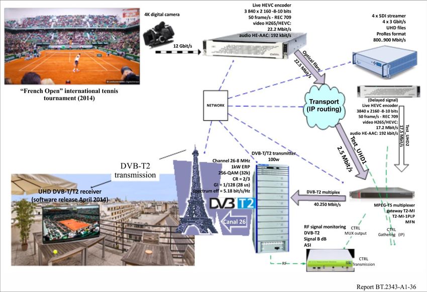
2                                                    Rep. ITU-R BT.2343-6

                                                                                                                                            Page
    4.2        Trials by the Chair of RTVE in UPM during the 2016-2019 period ..................                                              53

5   Sweden ...........................................................................................................................        60

6   United Kingdom .............................................................................................................              60

7   Brazil ..............................................................................................................................     61
    7.1        Introduction.........................................................................................................          61
    7.2        Diagram of the PV ..............................................................................................               61
    7.3        Transmission and reception station equipment...................................................                                61
    7.4        Transmission parameters ....................................................................................                   63
    7.5        Field tests in Rio de Janeiro ................................................................................                 65
    7.6        Measurements .....................................................................................................             65
    7.7        Demonstration.....................................................................................................             66
    7.8        Conclusion ..........................................................................................................          67

8   China...............................................................................................................................      67
    8.1        Introduction.........................................................................................................          67
    8.2        Diagram of the trial .............................................................................................             67
    8.3        Transmission and reception station equipment...................................................                                68
    8.4        Transmission parameters ....................................................................................                   69
    8.5        Field tests in Jiaxing ...........................................................................................             70
    8.6        Measurements .....................................................................................................             70
    8.7        Conclusion ..........................................................................................................          75
Rep. ITU-R BT.2343-6                                            3

1       Introduction
Ultra high definition television (UHDTV) is one of the major applications of next-generation digital
terrestrial broadcasting. Several countries have already started studies on digital terrestrial
broadcasting transmission systems that have significantly expanded their transmission capacities by
means of, for example, high multilevel modulation technology. Moreover, some countries have
already carried out UHDTV field experiments on digital terrestrial broadcasting to demonstrate the
feasibility of these systems. The compilation of a summary of these experiments will offer useful
information to administrations and broadcasters wishing to introduce or consider UHDTV
broadcasting in the future, as well as to manufacturers wishing to engage with this.
UHDTV production of big live events has already started, notably the 2014 FIFA World Cup in Brazil
where three games hosted in the Epic Maracana Stadium were officially produced and distributed
worldwide in 4k UHDTV. The EBU, by means of its operational branch (EUROVISION), ensured
the worldwide delivery of the three games over its satellite and fibre network.
In Japan, 8K UHDTV field transmission experiments with 4096-QAM and dual-polarized multiple
input multiple output (MIMO) technology were conducted in January 2014.
In the Annex, the Report presents an overview of the experiments, key technologies, and the results
conducted in various countries.
The intent of this Report is to provide evidence about the suitability of terrestrial television networks
to deliver UHDTV services to consumers on a large scale.

2       Status of standardization of UHDTV

2.1     Standardization within ITU
The standardization of parameters for Ultra High Definition is underway at ITU-R and different
Recommendations and Reports have been published, for example:
•       Recommendation ITU-R BT.2020-2 (10/2015) – Parameter values for ultra-high definition
        television systems for production and international programme exchange.
•       Recommendation ITU-R BS.2051-2 (07/2018) – Advanced sound system for programme
        production.
•       Report ITU-R BT.2246-6 (03/2017) – The present state of ultra-high definition television.
Other standardization activities on UHDTV are ongoing in ITU-R and ITU-T.

2.2     Standardization within DVB
The standardization process is also well underway at the DVB level, with the Standard TS 101 154
V2.5.1 published (01/2019) as DVB Blue Book A001 (7/2019) Specification for the use of Video and
Audio Coding in Broadcasting and Broadband Applications.

2.3     Standardization within TTA
On August 30, 2013, the scenarios for 4K-UHDTV service were described in the Report
“TTAR-07.0011: A Study on the UHDTV Service Scenarios and its Considerations”.
On May 22, 2014, the technical report “TTAR-07.0013: Terrestrial 4K UHDTV Broadcasting
Service” was published.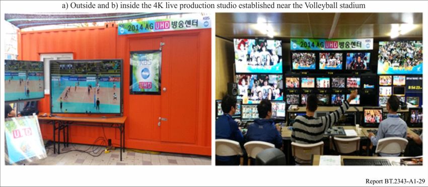
4                                   Rep. ITU-R BT.2343-6

On October 13, 2014, an interim standard – “TTAI.KO-07.0123: Transmission and Reception for
Terrestrial UHDTV Broadcasting Service” – was published based on HEVC encoding, with MPEG-2
TS, and DVB-T2 serving as the standards.
On June 24, 2016, a standard – “TTAK.KO-07.0127: Transmission and Reception for Terrestrial
UHDTV Broadcasting Service” – was published based on HEVC encoding, with MMTP/ROUTE IP,
and ATSC 3.0 serving as the standards.

3       Field Status of standardization of UHDTV
The Annex shows details of trials conducted for UHDTV over terrestrial television networks.
The following Table summarizes the trials and indexes the Annex.
Rep. ITU-R BT.2343-6                                                                                        5

                                                            Summary of UHDTV trials on terrestrial television networks
                                                                                                                                                   Video                       Audio
    Annex                 Transmitter                                 DTT       Channel        Transmission        Multiplex     Signal bit                     Picture                     Frequency
               Country                    Covering          e.r.p.                                                                               encoding                    encoding
    section                  site                                    System    bandwidth          mode             capacity         rate                       standard                        used
                                                                                                                                                 standard                    standard
                         Hitoyoshi      City of         140W(H)      ISDB-T2 6 MHz         32k                   91.8 Mb/s     91 Mb/s         MPEG-4       7 680×4 320p    MPEG-4       671 MHz
                                        Hitoyoshi       135W(V)                            GI = 1/32                                           AVC/H.264,   59.94 frame/s   AAC-LC       (Ch 46 in
      1.2                                                                                  4096-QAM,                                                        8 bits/pixel    Max. 22.2ch, Japan)
                                                                                           FEC 3/4                                                                          Max. 1.8
                                                                                                                                                                            Mb/s
                                                                                           dual-polarized MIMO
                         Hitoyoshi      City of         Hitoyoshi                          Space Time Coding-SFN 91.8 Mb/s     91 Mb/s          HEVC        7 680×4 320p
                         Mizukami       Hitoyoshi       140W(H)                            32k                                 (other bit rates             59.94 frame/s
                                                        135W(V)                            GI = 1/32                           also tested)                 10 bits/pixel
      1.3                                                                                  4096-QAM,
                                                        Mizukami                           FEC 3/4
                                                        25W(H)                             dual-polarized MIMO
                                                        25W(V)
                         Kinuta Tokyo   Southern area   93W(H)                             16k                   84.2 Mb/s     76 Mb/s         MPEG-4       7 680×4 320p                   581 MHz
              Japan                     of Tokyo        93W(V)                             GI = 1/16                                           AVC/H.264    59.94 frame/s                  (Ch 31 in
      1.4                                                                                  4096 NUC,                                                        8 bits/pixel                   Japan)
                                                                                           FEC 3/4
                                                                                           dual-polarized MIMO
                         Shiba          Central Tokyo 2.1 kW(H)               6 MHz        16k                   32.9~65.8     28~56 Mb/s      HEVC         7 680×4 320p    MPEG-H 3D      563 MHz
                                                      2.1 kW(V)                            GI = 800/16384        Mb/s                                       59.94 frame/s   Audio LC       (Ch 28 in
                                                                                                                                                            10 bits/pixel   level 4        Japan)
                                                                                           1024 NUC                            (+ additional
                         Higashiyama    City of Nagoya Higashiyama                                                             1~2 Mb/s for                                 Max. 22.2ch    605 MHz
                                                                                           FEC 11/16
                                                                                                                               HDTV)                                        + 3 objects
                         Nabeta                        980 W(H)                            SISO and                                                                                        (Ch 35 in
      1.5                                                                                                                                                                   768 kb/s       Japan)
                                                       980 W(V)                            dual-polarized MIMO                                                              (512 kb/s to
                                                                                                                                                                            1.4 Mb/s)
                                                        Nabeta
                                                        81 W(H)
                                                        81 W(V)

2     Some parameters are extended from conventional ISDB-T system (System C of Recommendation ITU-R BT.1306).
6 Rep. ITU-R BT.2343-6
Summary of UHDTV trials on terrestrial television networks
Transmission Video Audio
Annex Transmitter DTT Channel Multiplex Signal bit Picture Frequency
Country Covering e.r.p. encoding encoding
section site System bandwidth mode capacity rate standard used
standard standard
Kwan-Ak South 36.7 kW DVB-T2 6 MHz 32k, extended mode, < 35.0 Mb/s Variable HEVC Main10 3 840×2 160p MPEG-4 713 MHz
Mountain Metropolitan GI = 1/16, (some trials at Level 5.1, 60 frames/s, AAC-LC (Ch 54 in
area of Seoul 25~34 Mb/s) Max 28 Mb/s 8 bits or or Korea)
PP4,
12.9 kW 10 bits/pixel Dolby 701 MHz
AC-3, (Ch 52 in
256-QAM, FEC 3/4, 4/5,
5/6 Korea)
Korea 40.0 kW Max 5.1Ch, 707 MHz
2.1 (Republic Max 600 (Ch 53 in
of)3 kb/s Korea)
Nam Central area of 2.2 kW 713 MHz
Mountain Seoul (Ch 54 in
Korea)
Yong-Moon West 8.3 kW 707 MHz
Mountain Metropolitan (Ch 53 in
area of Seoul Korea)
2.2 Korea Kwan-Ak South 39.6 kW ATSC 6 MHz 32k, NoC = 0, < 30.0 Mb/s Variable HEVC Main10 3 840×2 160p MPEG-H 3D 701 MHz
(Republic Mountain Metropolitan 3.0 GI6_1536, (17 Mb/s) Level 5.1, 60 frames/s, Audio (Ch 52 in
of) area of Seoul Korea)
PP16_2, 10 bits/pixel
Variable ( Max 10.2Ch, 707 MHz
256-QAM, 9/15 15.5 Mb/s) (Ch 53 in
Korea)
762 MHz
(Ch 55 in
Korea)
Nam Central area of 18.9 kW 768 MHz
Mountain Seoul (Ch 56 in
Korea)
Gwang-Gyo Suwon (Capital 7.96 kW
Mountain city of
Gyeonggi
province)
3 Details for Korea in Table 1 correspond to Phase 3 of the trials. See § 2.1 for more details of Phases 1 and 2.
Rep. ITU-R BT.2343-6 7
Summary of UHDTV trials on terrestrial television networks
Video Audio
Annex Transmitter DTT Channel Transmission Multiplex Signal bit Picture Frequency
Country Covering e.r.p. encoding encoding
section site System bandwidth mode capacity rate standard used
standard standard
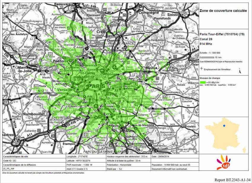
3.1 France Eiffel Tower City of Paris 1 kW DVB- 8 MHz 32k, extended mode, 40.2 Mb/s Two HEVC 3 840×2 160p HE-AAC 514 MHz
T2 GI = 1/128, 256-QAM, programmes 50 frames/s 192 kb/s (Ch26 in
FEC2/3, PP7 carried: one 8 bits/pixel Region 1)
at 22.5
Mb/s, one at
17.5 Mb/s
3.2 Eiffel Tower City of Paris 5 kW DVB- 8 MHz 32k, extended mode, 34.2 Mb/s Two to three HEVC Various AAC 2.0 / 514 MHz
Paris Est T2 GI = 1/32, 256-QAM, (PP4) programmes combinations AC3+ (Ch26 in
Chenevières 300 W FEC3/5, PP4 or PP6 34.9 Mb/s carried, from between with Region 1) /
(PP6) 10 to 17 3 840×2 160p various 498 MHz
Meaux 40 W
Mb/s for 50 frames/s bitrates (Ch24 in
Chaville 3W UHD and 8 or 10 region 1)
Nantes City of from 3 to 17 bits/pixel and 1
Nantes 16 kW Mb/s for 920 x 1 080p
Toulouse City of HD-1080p 50 frames/s
Toulouse 500 W 8 or 10
bits/pixel
Statistical
multiplexing
of 3 UHD
programmes
32k, extended mode, 38.8 Mb/s Two 3 840×2 160p MPEG-H
GI = 1/32, 256-QAM, programmes 50 frames/s 435 kb/s
FEC2/3, PP6 carried: one 10 bits/pixel AC3+ 2.0
at 24.8 235 kb/s
Mb/s, one at
1 920 x 1 080p AAC 2.0
12.4 Mb/s 50 frames/s 134 kb/s
10 bits/pixel
Three
programmes
carried: one
UHD at 24
Mb/s, two
HD-1080p
from 2.5 to 7
Mb/s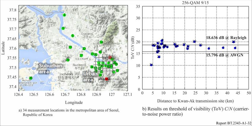
8 Rep. ITU-R BT.2343-6
Summary of UHDTV trials on terrestrial television networks
Video Audio
Annex Transmitter DTT Channel Transmission Multiplex Signal bit Picture Frequency
Country Covering e.r.p. encoding encoding
section site System bandwidth mode capacity rate standard used
standard standard
ETSI Tele- Ciudad 125 W DVB-T2 8 MHz 32k, extended mode, 36.72 Mb/s 35 Mb/s HEVC 3 840×2 160p E-AC-3 5.1 754 MHz
4.1 Spain comunicación Universitaria, GI = 1/128, 64-QAM, (other bit rates 50 frames/s (Ch56 in
Madrid FEC5/6, PP7 also tested) 10 bits/pixel Region 1)
ETSI Tele- Ciudad 125 W DVB-T2 8 MHz 32k, extended mode, 32.6 Mb/s 30 Mb/s HEVC 3 840×2 160p E-AC-3 5.1 658 MHz
comunicación Universitaria, GI = 1/128, 64-QAM, 50 frames/s (Ch 44 in
Madrid FEC3/4, PP7 10 bits/pixel Region 1)
4.2.1 Spain
Collserola Barcelona 15 kW 482 MHz
(Channel 22
in Region 1)
Torrespaña and Madrid 15 kW DVB-T2 8 MHz 32k, extended mode, 33.4 Mb/s 30 Mb/s HEVC 3 840×2 160p AC-4 and E- 562 MHz
San Fernando Torrespaña GI = 1/8, 256-QAM, 50 frames/s AC-3 5.1 (Channel 32
75 W San FEC2/3, PP2 10 bits/pixel in Region 1)
Fernando HDR 10
Collserola and Barcelona 10 kW Dolby Vision 650 MHz
4.2.2 Spain Baix Llobregat Collserola (Channel 43
12 W Baix in Region 1)
LLobregat
Valencina Sevilla 9 KW 594 MHz
(Channel 36
in Region 1)
ETSI Tele- Ciudad 125 W DVB-T2 8 MHz 32k, extended mode, 33.4 Mb/s 30 Mb/s HEVC 3 840×2 160p AC-4 5.1 658 MHz
comunicación Universitaria, GI = 1/8, 256-QAM, 100 frames/s (Channel 44
Madrid FEC2/3, PP2 in Region 1)
10 bits/pixel
Torrespaña and Madrid 15 kW HDR 10 562 MHz
San Fernando Torrespaña WCG (Channel 32
75 W San in Region 1)
Fernando
Collserola and Barcelona 10 kW 650 MHz
4.2.3 Spain Baix Llobregat Collserola (Channel 43
12 W Baix in Region 1)
LLobregat
Valencina Sevilla 9 kW 594 MHz
(Channel 36
in Region 1)
Mijas Malaga 2 kW 514 MHz
(Channel 26
in Region 1)Rep. ITU-R BT.2343-6 9
Summary of UHDTV trials on terrestrial television networks
Annex Country Transmitter Covering e.r.p. DTT Channel Transmission Multiplex Signal bit Video Picture Audio Frequency
section site Syste bandwidth mode capacity rate encoding standard encoding used
m standard standard
Monte Pedroso Santiago de 9 kW 570 MHz
Compostela (Channel 33
in Region 1)
Stockholm City of 35 kW DVB-T2 8 MHz 32k, extended mode, 31.7 Mb/s 24 Mb/s HEVC 3 840×2 160p 618 MHz (Ch
5 Sweden Nacka Stockholm GI = 19/256, 256-QAM, 29.97 frames/s 39 in Region
FEC 3/5, PP4 8 bits/pixel 1)
Crystal Palace Greater 40 kW DVB-T2 8 MHz 32k, extended mode, 40.2 Mb/s Variable (some HEVC Mixture of 586 MHz
London GI = 1/128, 256-QAM, trials at 35 3 840×2 160p (Ch 35 in
(serving over FEC 2/3, PP7 Mb/s) 50 frames/s and Region 1)
4.5 million 3 840×2 160p
households) 59.94 frames/s
Winter Hill North-west of 22.5 kW 8 MHz 602 MHz
Most of the trial
England, (Ch 37 in
at 8 bits/pixel,
including Region 1)
some at 10
Manchester
bits/pixel
and Liverpool
6 UK (serving 2.7
million
households)
Black Hill Central 39 kW 8 MHz 586 MHz
Scotland, (Ch 35 in
including Region 1)
Glasgow and
Edinburgh
(serving 1
million
households)
Mt. Sumaré Parts of Rio de 660 W(H) ISDB-T1 6 MHz 32k 91.8 Mb/s 85 Mb/s HEVC 7 680×4 320p MPEG-4 569 MHz
Janeiro 660 W(V) GI = 1/32 59.94 frame/s AAC (Ch 30 in
metropolitan 10 bits/pixel 1.48 Mb/s Brazil)
7 Brazil 4096-QAM,
area
FEC 3/4
dual-polarized MIMO
Jiaxing Radio Jiaxing City 10 KW DTMB-A 8 MHz 32k 39.7 Mb/s 36 Mb/s H.265 3840 × 2160p MPEG-4 562 MHz
and Television urban and GI = 1/64 50 frame/s AAC DS-24
8 China Building country side 384 Kbit/s
256APSK
FEC 2/3
GI = guard intervals10 Rep. ITU-R BT.2343-6
Annex
Field Experiments of UHDTV Terrestrial Transmission
1 Japan
1.1 Introduction
Next-generation digital terrestrial television broadcasting will be dominated by UHDTV applications.
UHDTV broadcasts consist of a huge amount of data and therefore require large-capacity
transmission paths.
Japan is conducting research on large-capacity transmission technology for next-generation digital
terrestrial broadcasting systems that will provide large-volume content services such as 8K. In order
to transmit the 8K signal, which has a resolution 16 times greater than HDTV, it will be essential to
utilize new technologies that expand transmission capacity, such as ultra-multilevel (4096-QAM),
orthogonal frequency-division multiplexing (OFDM), and dual-polarized multiple-input multiple-
output (MIMO).
This experiment establishes parameters for maximizing transmission capacity. However, in actual
implementation, these parameters will have to be decided taking link budget, the transmission
network, the receiving environment, and other factors into account.
A R&D project on an advanced digital terrestrial television broadcasting (DTTB) system is in
progress under the auspices of the Ministry of Internal Affairs and Communications, Japan. The
project is aiming at developing an advanced DTTB system. The system being developed in this
project (hereafter referred to as advanced system) is under evaluation through field trials in large-scale
experimental environments constructed in urban areas.
1.2 8K-UHDTV field experiments in rural area; Hitoyoshi (2 2 MIMO transmission
system)
Japan has installed an experimental transmitting station in Hitoyoshi city, Kumamoto prefecture that
uses dual-polarized MIMO and ultra-multilevel OFDM technologies. Two 8K field experiments were
conducted there: a transmission test and field measurements at 52 points around Hitoyoshi.
Here, Japan reports the results of these experiments, including the required field strength when using
4096-QAM carrier modulation and a channel response analysis of dual-polarized MIMO
transmission.
1.2.1 Transmission parameters and experiment area
Table 1 lists the specifications of the 8K field experiments in the Hitoyoshi area.
TABLE 1
Specifications of 8K field experiments in Hitoyoshi
Modulation method OFDM
Occupied bandwidth 5.57 MHz
Transmission frequency 671.142857 MHz (UHF ch46)
Horizontal polarized waves: 10 W, e.r.p.: 140 W
Transmission power
Vertical polarized waves: 10 W, e.r.p.: 135 W
Carrier modulation 4096-QAMRep. ITU-R BT.2343-6 11
TABLE 1 (end)
FFT size (number of radiated carriers) 32k (22,465)
Guard interval ratio (guard interval duration) 1/32 (126 μs)
Inner: LDPC, code rate = 3/4
Error-correcting code
Outer: BCH
Transmission capacity 91.8 Mb/s
Video coding MPEG-4 AVC/H.264, HEVC
Audio coding MPEG-4 AAC
Transmitting station Established at NHK Hitoyoshi TV relay station
632 m above sea level
Height of transmitting antenna
(21 m above ground level)
1.2.2 Transmitting and receiving station equipment
Table 2 shows the requirements for selecting the field experiment locations. The Hitoyoshi area fulfils
these requirements and so it was chosen as the place to set up the experimental transmitting station.
Figure 1 shows the transmitting station and equipment and Fig. 2 shows the receiving station and
equipment. An 85-inch 8K monitor was used to display the 8K signal. Both the dual-polarized
transmitting antenna and the dual-polarized receiving antenna were developed.
Figure 3 is a block diagram of the modulator and demodulator used in the experiments. The input
signal is coded with BCH code and low density parity check (LDPC) code, bit interleaved and mapped
onto the constellation. After that, the signal is divided into two signals (one for horizontal polarization
and the other for vertical) with 3D interleave (time, frequency and inter-polarization). The signals are
then converted into time domain signals by inverse fast Fourier transform (IFFT) and guard intervals
(GI) are added.
The signals from the modulator are converted into RF signals of the same frequency by using up-
converters (U/C). The signals are then amplified with a power amplifier (PA) to the desired power
level and transmitted as horizontal and vertical polarized waves from a dual-polarized antenna.
The transmitted signals are received by a dual-polarized Yagi antenna. Each received signal is filtered
by a band-pass filter (BPF) and input to a variable attenuator (ATT). The signals are then amplified
using low noise amplifiers (LNA) and converted into IF signals with a down converter (D/C). The IF
signals are then input to the demodulator.
In the demodulator, the active symbol period is extracted from the received signals, which are then
converted into frequency domain signals by fast Fourier transform (FFT). The frequency domain
signals are de-multiplexed, equalized by MIMO detection, 3D de-interleaved, and used to calculate
the log likelihood ratio (LLR). LLRs are de-interleaved and input to the LDPC decoder. Finally, BCH
decoding is applied to obtain the output signal.
In the transmission test, compressed 8K signals were transmitted over a single UHF-band channel
(6 MHz bandwidth). The distance between the transmitting station and receiving station was 27 km,
a typical distance for current digital terrestrial broadcasting.12 Rep. ITU-R BT.2343-6
TABLE 2
Location requirements for 8K field experiments
1 The place should have a vacant UHF single channel for 8K transmission.
To analyse the channel response of dual-polarized MIMO transmission, the experiment should be
2
able to be conducted over a large area and over long distances (e.g. transmissions over 20 km).
3 The place should support a current DTTB system.
4 The place should be free of mutual interference from other areas.
FIGURE 1
Transmitting station and equipment
FIGURE 2
Receiving station and equipmentRep. ITU-R BT.2343-6 13
FIGURE 3
Block diagram of 8K experiments
1.2.3 Key technologies
Ultra-multilevel OFDM is a technology that applies a greater number of signal points to data symbols.
Carrier modulation schemes up to 64-QAM can be used in current ISDB-T, but up to 4096-QAM can
be implemented in the prototype equipment. Figure 4 shows the constellations of 64-QAM and
4096-QAM. 64-QAM can transmit six bits of data per carrier symbol, while 4096-QAM can transmit
12 bits per carrier symbol, which is twice as many as 64-QAM.
FIGURE 4
Constellations of 64-QAM (left) and 4096-QAM (right)14 Rep. ITU-R BT.2343-6
Dual-polarized MIMO is a technology configuring MIMO with two orthogonal polarizations. This
technology was used to expand the transmission capacity, and namely each of the two polarized waves
transmitted different data. A dual-polarized MIMO using horizontally and vertically polarized waves
can be used as the model, as shown in Fig. 5.
FIGURE 5
MIMO transmission model
1.2.4 Field measurement results
For the field test, 52 reception points in the Hitoyoshi area that were 1.3 km to 36.7 km from the
transmitter were selected (Fig. 6). MIMO propagation measurements were conducted at all 52 points
and the BER (after the BCH decoding) and receiving margin were measured at each carrier
modulation at 30 points.
FIGURE 6
Location of reception pointsRep. ITU-R BT.2343-6 15
Figure 7 plots the average field strength of the BER and receiving margin measurements at the
30 reception points. The horizontal axis is the transmission distance (km) and the vertical axis is the
average field strength of both polarized waves. These results indicate that quasi error free (QEF)
transmission is possible with the 4096-QAM carrier modulation scheme. In this Annex, the QEF is
defined that there is no error for a measurement time of two minutes.
FIGURE 7
Average field strength vs. transmission distance
The required field strength, which is defined as the lowest field strength for QEF transmission, was
determined by decreasing the input signal level of the LNA by using the ATT.
Table 3 lists the average required field strengths, which were calculated by averaging the horizontal
and vertical polarized waves. The average required field strength increased by about 5 dB as a result
of quadrupling the number of signal points in the constellation.
TABLE 3
Average required field strength for QEF
Average required field strength
Carrier modulation scheme Number of QEF points
(dBμV/m)
256-QAM 42.4 23
1024-QAM 47.3 22
4096-QAM 52.3 21
The transmission characteristics were analysed at all 52 points of the MIMO propagation
measurement. The propagation environment was classified into four categories: line of sight (LoS),
non-line of sight (NLOS) with a strong field strength (over 60 dBμV/m), NLOS with a moderate field
strength (40-60 dBμV/m), and NLOS with a weak field strength (under 40 dBμV/m).16 Rep. ITU-R BT.2343-6
Figure 8 shows an example of the MIMO channel responses of NLOS with a moderate field strength.
An example of the distribution of the condition numbers of the four categories is presented in Fig. 9.
The analysis indicates that the MIMO propagation qualities became worse starting with LoS and
followed by NLOS with a strong field strength, NLOS with a moderate field strength, and NLOS
with a weak field strength. This order is attributed to the increase of the cross polarized wave
components. It was also shown that the condition number increased and the distribution of the
condition number spread out in the same order as above.
FIGURE 8
Example of MIMO channel responses of NLOS with a moderate field strengthRep. ITU-R BT.2343-6 17
FIGURE 9
Example of distribution of condition number of four categories
1.3 8K-UHDTV SFN field experiments in rural area; Hitoyoshi (2 2 MIMO STC-SFN
transmission system)
In February 2015, Japan conducted 8K-UHDTV single frequency network (SFN) field experiments
using two transmission stations to form a 2 × 2 MIMO Space Time Coding (STC)-SFN system. In
this field experiment, the STC method was employed to improve the reliability of high data rate
transmission. In November 2016, an 8K-UHDTV field experiment using high efficiency video coding
(HEVC) was conducted. It was confirmed that the video and audio were successfully received within
the STC-SFN area.
1.3.1 Overview of 2 2 MIMO STC-SFN
Figure 10 shows the outline of a 2 2 MIMO STC-SFN system formed by two experimental stations,
namely, the Hitoyoshi and Mizukami stations. The distance between the two stations is 38 km. Both
stations use dual-polarized space division multiplexing (SDM) MIMO. The Mizukami station became
operational in 2015 and was connected to the Hitoyoshi station by a transmitter to transmitter link
(TTL) in the super high frequency (SHF) band.
In this field experiment, the intermediate frequency TTL (IF-TTL) method was used to transmit an
OFDM signal from the Hitoyoshi station to the Mizukami station. The transmission frequencies of
the two stations were precisely synchronized by rubidium (Rb) oscillator with a global positioning
system (GPS) as a backup.
The 22 MIMO STC-SFN system used in this SFN field experiment employed STC technology as a
new feature. The Hitoyoshi station transmitted a 91 Mbit/s 8K-UHDTV signal in a 6 MHz bandwidth
UHF channel (channel number 46 in Japan), and the Mizukami station also transmitted using the
same channel.18 Rep. ITU-R BT.2343-6
FIGURE 10
Outline of 22 MIMO STC-SFN transmission system
1.3.2 Transmission parameters and equipment
Table 4 shows the parameters for MIMO transmission, and Table 5 the specifications of the Hitoyoshi
and Mizukami stations. Figure 11 shows the equipment installed in each station, and Fig. 12 shows
the transmission and reception antennas for the UHF channel. The transmission antennas at Hitoyoshi
and Mizukami have the same characteristics.
TABLE 4
Parameters for MIMO transmission
Modulation method OFDM
Occupied bandwidth 5.57 MHz
Carrier modulation 4096-QAM
FFT size (number of radiated carriers) 32K (22,465)
Guard interval ratio (guard interval duration) 1/32 (126 μs)
Error-correcting code Inner code: LDPC, coding rate R = 3/4
Outer code: BCH
Transmission capacity 91.8 Mbit/s
TABLE 5
Specifications of Hitoyoshi and Mizukami stations
Hitoyoshi station Mizukami station
Transmission frequency 671.142857 MHz (UHF ch46 in Japan)
Transmission power Horizontal: 10 W Horizontal: 3 W
Vertical: 10 W Vertical: 3 W
e.r.p. Horizontal: 140 W Horizontal: 25 W
Vertical: 135 W Vertical: 25 W
Transmitting antenna height 632 m above sea level 1080 m above sea levelRep. ITU-R BT.2343-6 19
FIGURE 11
Equipment of MIMO experimental stations
FIGURE 12
Transmission and reception antennas for UHF
The 2 2 MIMO STC-SFN system was developed for this experiment as shown in Fig. 13. STC is a
method of encoding carrier symbols. An STC code is applied for the four carrier symbols of the two
transmission antennas each of two transmission stations. Here, s is a carrier symbol of a constellation
with a complex value, and “*” means the complex conjugate. The transmitted symbols s0, s1, s2 and s3
are encoded, s0, s1, -s2* and s3* are transmitted in time t, and s2, s3, s0* and -s1* are then transmitted in
time t+1, from each antenna. In the transmission model, the transmitting carrier symbols are denoted
as x0, x1, x2 and x3, and the receiving carrier symbols as y0 and y1. h is the channel response estimated
by scattered pilot (SP), and hij is the component corresponding to the ith receiving antenna and jth
transmitting antenna. In the reception model, the transmitted symbols s0, s1, s2 and s3 are obtained by
decoding the received symbols y0 and y1, which are received at two discrete times.
Figure 14 shows the block diagram of the 2 2 MIMO STC-SFN system modulator and demodulator
used in this field trial. Figure 15 shows the SP patterns of the 2 2 MIMO STC-SFN system. To
estimate the channel responses of each receiving antenna, four orthogonal SP schemes using sign
inversion were investigated. These SP patterns are the extensions of those used by ISDB-T.
In order to adjust the time delay between two transmission waves, IF delay adjustment equipment
with a range of 0.1 µs – 10 m s (shown in Fig. 15) was installed at both stations.20 Rep. ITU-R BT.2343-6
FIGURE 13
2 2 MIMO STC-SFN systemRep. ITU-R BT.2343-6 21
FIGURE 14
Block diagram of 2 2 MIMO STC-SFN system
FIGURE 15
Scattered pilot patterns22 Rep. ITU-R BT.2343-6
1.3.3 Field measurements
The conventional SFN is defined as two geographically distributed stations sending exactly the same
signals synchronously using the same frequency. In this conventional SFN, a deep null is generated
within the reception spectrum and causes deterioration of signal quality. This problem is caused by
an erasure effect, the so-called 0-dB echo effect.
To compare the differences between 2 2 MIMO STC-SFN system and conventional SFN system,
transmission characteristics were measured at three points (Points A, B, and C in Fig. 16) within the
area of overlap covered by both the Hitoyoshi and the Mizukami stations. Here, LoS stands for line
of sight and NLOS stands for non-line of sight.
Before measurement, the transmission power and time delay at both stations was adjusted for
evaluation under identical conditions. The power ratios of the main and SFN waves were adjusted to
6 dB and the time delay between the main and SFN waves to 2 µs at the receiver inputs at each test
point. The power of each wave was defined as the average of the horizontal and vertical waves.
Figure 17 plots the reception powers required for both 2 2 MIMO STC-SFN and conventional SFN
at all three reception points. This Figure clearly shows that the null is much shallower in the spectrum
of 2 2 MIMO STC-SFN than in conventional SFN. Furthermore, the power requirement for 2 2
MIMO STC-SFN is as much as 3 dB superior to that of the conventional SFN. This decreased null
and superior power requirement are clear outcomes of the application of STC technology to SFN.
An 8K-UHDTV field experiment with HEVC was conducted at Point C in Fig. 16. The 8K video
compressed with HEVC and a multi-dimensional audio (22.2 channels) compressed with MPEG-4
AAC were transmitted from two experimental stations (Hitoyoshi and Mizukami) to create an
STC-SFN. The received signals were demodulated and the 8K video was displayed on an 85-inch
LCD display. The transmission parameters were the same as those in the previous § 1.3.2. Figure 18
shows the reception equipment for the demonstration. In this experiment, it was demonstrated that
8K-UHDTV can be successfully delivered with STC-SFN.
FIGURE 16
Measuring pointsRep. ITU-R BT.2343-6 23
FIGURE 17
Comparison of 2 2 MIMO STC-SFN with conventional SFN
FIGURE 18
Demonstration of 8K-UHDTV transmission with STC-SFN
1.4 8K-UHDTV field experiments with non-uniform constellation in urban area; Kinuta,
Tokyo (2 2 MIMO transmission system)
An 8K-UHDTV field experiment with non-uniform constellation (NUC), in which the signal points
in the constellation are distributed non-uniformly, was conducted in an urban area; Kinuta, Tokyo.
1.4.1 Overview of non-uniform constellation
The NUC is a technology to improve the transmission performance by adjusting the distance between
the signal points to be suited for the noise in the propagation channel. It is confirmed that the greater
number of signal points in the constellation, such as 4096QAM, the larger improvement in performance
is obtained. The signal points of the 4096 NUC implemented on the prototype transmission system and
conventional 4096 uniform constellation (UC) are depicted in Fig. 19. In this Figure, the average power24 Rep. ITU-R BT.2343-6
of NUC is normalized to be the same as that of UC, and the signal points of 4096 NUC are optimized
for 30 dB of carrier to noise ratio (C/N) as the expected C/N in the transmission channel.
FIGURE 19
1.4.2 Transmission parameters and equipment
An experimental station was installed on top of the NHK – Science and Technology Research
Laboratories (STRL) located in southern Tokyo, and a field experiment was conducted with NUC in an
urban area. The transmission parameters are listed in Table 6. The experimental station is composed of
two transmitters for horizontally and vertically polarized waves. The experimental signals were
received at a reception point 8 km from the transmitting point. The block diagram of the experiment is
shown in Fig. 20. In this Figure, horizontal and vertical are expressed as H and V, respectively. The
transmitting and receiving antennas are shown in Fig. 21. A dual-polarized dipole antenna was used for
the transmitting antenna and a dual-polarized Yagi antenna was used for the receiving antenna. The
view from the transmitter toward the reception point and that from the reception point toward the
transmitter are shown in Fig. 22. The reception antenna was located at a LOS point, however multipath
echoes reflected by the buildings on the propagation path were observed. It was confirmed that MIMO
transmission with NUC can deliver 8K video stably in such an urban area. The demonstration of
8K-UHDTV reception with NUC is shown in Fig. 23.
TABLE 6
Specifications of 8K field experiments in urban area (Kinuta, Tokyo)
Modulation method OFDM
Occupied bandwidth 5.57 MHz
Transmission frequency 581.142857 MHz (UHF ch31)
Horizontal polarized waves: 10 W, e.r.p.: 93 W
Transmission power
Vertical polarized waves: 10 W, e.r.p.: 93 W
Carrier modulation 4096 NUC
FFT size (number of radiated carriers) 16k (11,233)
Guard interval ratio (guard interval duration) 1/16 (126 μs)
Inner: LDPC, code rate = 3/4
Error-correcting code
Outer: BCH
Transmission capacity 84.2 Mb/sRep. ITU-R BT.2343-6 25
TABLE 6 (end)
Video coding MPEG-4 AVC/H.264
Audio coding MPEG-4 AAC
Transmitting station Established at NHK-STRL
126 m above sea level
Height of transmitting antenna
(96 m above ground level)
FIGURE 20
Block diagram of 8K experiments in urban area
FIGURE 21
Transmission and reception antennas for experiments in urban area
FIGURE 22
View from transmission and reception sites26 Rep. ITU-R BT.2343-6
FIGURE 23
Demonstration of 8K-UHDTV transmission with NUC
1.4.3 Field measurements
The transmission performance of NUC was evaluated at three reception points in Tokyo. The
improvement of NUC over UC in the C/N was investigated. The results are listed in Table 7. It was
confirmed that NUC improved the transmission performance by about 1 dB in a MIMO transmission
system using 4096-QAM in an urban area.
TABLE 7
Required C/N improvement of non-uniform constellation over uniform constellation
Reception point Improvement Transmission distance
(A) Hanegi park 0.9 dB 4.5 km
(B) NHK Broadcasting Centre 0.9 dB 8.0 km
(C) Meijijingu Gaien 1.0 dB 10.4 km
1.5 4K/8K-UHDTV field experiments with advanced system in urban area; Tokyo and
Nagoya
1.5.1 Overview of advanced DTTB system
The objective of the advancement is to provide improved transmission performance compared to
ISDB-T in terms of the increased transmission capacity and the reduced C/N required. The advanced
system has been designed to inherit the feature of ISDB-T, i.e. it aims to provide a 4K or 8K UHDTV
service for fixed reception and an HDTV service for mobile reception simultaneously by frequency
division multiplexing (FDM) within a single channel. It also uses a frequency-segmented structure
that allows partial reception. The bandwidth per segment is reduced to increase the number of
segments from 13 (for ISDB-T) to 35, allowing for flexible bitrate distribution between layers such
as the mobile reception layer and fixed reception layer. The advanced system allows a higher spectral
efficiency and/or a transmission robustness with multiple-input multiple-output (MIMO).
A prototype modulator and demodulator for the advanced system were developed and their
performances were confirmed through laboratory experiments. The feasibility of the system is being
verified through large-scale field trials in urban areas.
1.5.2 Transmission parameters
Field experiments were conducted with the parameters listed in Table 8. The occupied bandwidth was
expanded by about 5% compared to that of ISDB-T to increase transmission capacity. The 31 and 4
segments out of 35 segments were assigned for UHDTV and HDTV services, respectively. As forRep. ITU-R BT.2343-6 27
error-correcting code and carrier modulation, low density parity check (LDPC) code and NUCs were
used for both UHDTV and HDTV services to enhance transmission robustness.
TABLE 8
Parameters for field experiments of hierarchical transmission in urban area
(Tokyo and Nagoya)
Modulation method OFDM
Occupied bandwidth 5.83 MHz
Reception scenario Fixed (Rooftop) Mobile (Car-mounted)
Number of segments 31 4
Carrier modulation 1 024 NUC QAM 64 NUC QAM
FFT size (number of radiated carriers) 16 k (15,121)
Guard interval ratio (guard interval duration) 800/16384 (126 μs)
Error-correcting code Inner: LDPC, code rate = Inner: LDPC, code rate =
11/16 7/16
Outer: BCH Outer: BCH
Transmission capacity 31.4 Mb/s (SISO) 1.5 Mb/s (SISO)
62.8 Mb/s (MIMO) 3.0 Mb/s (MIMO)
Video coding HEVC
Video format 3840 × 2160/60/P (4K)
1920 × 1080/60/P (2K)
7680 × 4320/60/P (8K)
Video bit rate SISO: 25 Mb/s (4K) SISO: 1.0 Mb/s (2K)
SISO: 28 Mb/s (8K)* MIMO: 1.0 Mb/s (2K)
MIMO: 56 Mb/s (8K)*
Audio coding MPEG-H 3D Audio LC level
MPEG-4 AAC
4
Audio bit rate 768 kb/s (22.2ch + 3 objects) 192 kb/s (2ch)
* Pre-processed before encoding by MPEG-H HEVC with a state-of-the-art software encoder offline taking
plenty of time.
1.5.3 Field measurements
To evaluate the performance of the advanced system in different propagation environments, large-scale
experimental environments were constructed. Two locations (in the Tokyo and Nagoya areas) were
selected to have the same scale as the main stations currently used for terrestrial broadcasting. Figure
24 shows the transmitter sites and assumed coverage areas for the experimental parameters in Table 8.
Table 9 lists the specifications of the transmission stations. Each transmission station is equipped with
two transmitters and two antennas for horizontally and vertically polarized waves. The directional
patterns of transmitting antennas at Nabeta relay station are designed to be selectable.28 Rep. ITU-R BT.2343-6
FIGURE 24
Experimental environments
a) Tokyo area b) Nagoya area
Assumed coverage: Shiba Assumed coverage: Higashiyama
Shiba Higashiyama
Nabeta
Assumed coverage: Nabeta pattern no.1
Assumed coverage: Nabeta pattern no.2
TABLE 9
Specifications of transmission stations
Tokyo area Nagoya area
Transmitter site Shiba (main station) Higashiyama (main station) Nabeta (relay station)
(Minato Ward, Tokyo) (Showa Ward, Nagoya, (Yatomi, Aichi)
Aichi)
Transmission 563.143 MHz 605.143 MHz
frequency
Polarization Horizontal, Vertical
Transmission Horizontal: 1 kW Horizontal: 1 kW Horizontal: 10 W
power Vertical: 1 kW Vertical: 1 kW Vertical: 10 W
e.r.p. Horizontal: 2.1 kW Horizontal: 980 W Horizontal: 81 W
Vertical: 2.1 kW Vertical: 980 W Vertical: 81 W
Transmitting 280 m above sea level 203 m above sea level 42.5 m above sea level
antenna height
Transmission experiments were conducted in the two experimental urban areas. Experiments were
launched in November and December 2018 in the Nagoya and Tokyo areas, respectively.
The experiments involved field trials of hierarchical transmission of UHDTV/HDTV using a single
channel based on the advanced DTTB system. The UHDTV (4K or 8K) content for fixed reception
and HDTV (2K) content for mobile reception shown in Table 8 were recorded in advance in a player,
and the video and audio streams were played back at the experimental stations. The block diagram of
transmitting and receiving system is shown in Figure 25. UHDTV and HDTV streams from the playerRep. ITU-R BT.2343-6 29
are multiplexed by the remultiplexer (remux) into a single IP stream and input to the advanced DTTB
modulator. The frequency of two output signals from the modulator are converted and power-
amplified by the transmitter. The audio of UHDTV was an object-based audio that transmitted a 22.2
channel audio encoded by MPEG-H 3D Audio and three narration objects in Japanese, English, and
French. For the HDTV content, the video was encoded by HEVC and the stereo audio signals were
encoded by MPEG-4 AAC.
Figure 26 shows the locations of the transmitting and receiving points in the Tokyo area. The NHK
Science and Technology Research Laboratories (NHK-STRL), which is approximately 12 km away
from the Shiba station, was selected as the receiving point. On the receiving side, the received
spectrum was observed by a spectrum analyser, and the delay profile was confirmed by a signal
analyser. The UHDTV signal output from the demodulator was decoded in real time by the HEVC
decoder and displayed on a 4K/8K LCD monitor. The 22.2 channel audio was decoded in real-time
by MPEG-H 3D Audio decoder, converted to 7.1 channel audio, and reproduced using a
commercially available sound bar. The HDTV signal was converted from multicast to unicast, then
transmitted via WiFi router, and decoded by an MMT player installed on a tablet or smartphone.
Figure 27 shows the spectrum of the received signals. Figures 28 and 29 show the delay profile and
constellation of the received signal of SISO transmission using horizontal polarized wave. As for the
delay profile, almost no reflected waves were confirmed as shown in Fig. 28. In this experiment, it
was demonstrated that UHDTV and HDTV contents can be successfully received with the advanced
DTTB system.
FIGURE 25
Block diagram of transmitting and receiving system in Tokyo30 Rep. ITU-R BT.2343-6
FIGURE 26
Locations of transmitting and receiving points in Tokyo
FIGURE 27
Spectrum of received signal at NHK-STRL (SISO)
Current DTTB signals (ISDB-T) Advanced DTTB
signal
Note: The advanced DTTB signal was allocated upper-adjacent to the current DTTB signals. The difference in the received power
between the advanced DTTB signal and the current DTTB signals is due to the different transmitting power and the transmitting points.Rep. ITU-R BT.2343-6 31
FIGURE 28
Delay profile of received signal at NHK-STRL (SISO)
FIGURE 29
Constellations of received signal at NHK-STRL (SISO)
(a) 1024 NUC QAM for UHDTV (b) 64 NUC QAM for HDTV
The block diagram of transmitting and receiving system in Nagoya is shown in Fig. 30. Figure 31 shows
the locations of the transmitting and receiving points in the Nagoya area. As a receiving point, the
Nagoya port building, which is approximately halfway between the Higashiyama and Nabeta
experimental stations, was selected. The remultiplexer was installed at the Higashiyama station and the
IP packet was sent to the two modulators installed at the Higashiyama and the Nabeta stations. A
200 Mbit/s bandwidth secured line was used as the IP line between the Higashiyama and Nabeta stations.
The radio waves were emitted from the two stations to carry out the transmission experiments in a SFN
environment. The modulated signals were generated at each transmission timing.
At the receiving point (the Nagoya port building), the receiving antenna was installed facing the
Nabeta station. Additionally, the transmission power of the Higashiyama station was adjusted to32 Rep. ITU-R BT.2343-6
demonstrate severe SFN reception conditions. As an example, the desired-to-undesired signal ratio
(DUR) of 3.2 dB and 1.9 dB for horizontal polarization and vertical polarization between the Nabeta
station (D) and the Higashiyama station (U) was demonstrated with the reduction in the transmission
power of the Higashiyama station by 5 dB for both polarizations. Regarding the delay setting of the
remultiplexer, the transmitting timings of the Higashiyama and the Nabeta stations were aligned at
the same time. As the Higashiyama station is geographically 500 m closer to the reception point than
the Nabeta station, it was expected that the transmitted signals from the Higashiyama station would
arrive 1.6 µs earlier than the signals from the Nabeta station. However, it was confirmed that the
signals from the Higashiyama station arrived about 2 µs later than the signals from the Nabeta station.
The delay was caused by a feedback compensation circuit installed in the transmitters at the
Higashiyama station.
Figures 32, 33 and 34 show examples of the spectrum, delay profiles, and reception constellations of
the received signals for MIMO transmission using horizontal and vertical polarizations. For the
reception spectrum, ripples caused by the undesired signals from the Higashiyama station were
confirmed. For delay profiles, horizontal to horizontal, horizontal to vertical, vertical to horizontal
and vertical to vertical components are shown in blue, green, yellow and pink, respectively. The
Higashiyama station is located in the direction opposite to the main lobe of the receiving antenna;
therefore, many reflected signals transmitted by the Higashiyama station were observed. The
demonstration of UHDTV/HDTV reception with the advanced DTTB system in the SFN environment
was presented to the press. It was confirmed that even under severe SFN reception conditions, the
UHDTV/HDTV video and audio could be received without any transmission errors.
FIGURE 30
Block diagram of transmitting and receiving system in NagoyaRep. ITU-R BT.2343-6 33
FIGURE 31
Locations of transmitting and receiving points in Nagoya
FIGURE 32
Spectrum of received signals at Nagoya port building (MIMO)
Horizontal
Vertical34 Rep. ITU-R BT.2343-6
FIGURE 33
Delay profile of received signals at Nagoya port building (MIMO)
FIGURE 34
Constellations of received signals at Nagoya port building (MIMO)
(a) 1024 NUC QAM for UHDTV (Horizontal) (b) 1024 NUC QAM for UHDTV (Vertical)
(c) 64 NUC QAM for HDTV (Horizontal) (d) 64 NUC QAM for HDTV (Vertical)Rep. ITU-R BT.2343-6 35 Transmission performance of the advanced system is being verified assuming a fixed rooftop reception with a reception antenna at a height of 10 metres and a mobile reception with vehicular external aerials at a height of 2 metres in the Tokyo and Nagoya areas. The plan is to evaluate the transmission characteristics not only of single-input single-output (SISO), but also MIMO to confirm the gain in the capacity and required C/N achieved with the advanced system in actual urban reception environments. 1.6 Summary In the field of broadcasting, 8K-UHDTV has the potential to succeed HDTV. Japan has set up an experimental station for 8K-UHDTV transmissions at Hitoyoshi city, Kumamoto prefecture, using dual-polarized MIMO and ultra-multilevel OFDM technologies. The field experiments performed there in January 2014 were the world’s first 8K-UHDTV terrestrial transmissions (91 Mbit/s) over a long distance (27 km) using a single UHF channel (6 MHz). This paper reported the results of those field experiments specific reference to the required field strength of the 256-QAM, 1024-QAM, and 4096-QAM carrier modulation and the channel response analysis of dual- polarized MIMO transmission. Japan has added another experimental station for 2 × 2 MIMO STC-SFN in the same city in 2015. The new field experiment so performed showed significant improvement over conventional SFN. In 2016, an 8K-UHDTV field experiment with HEVC was conducted using the two experimental stations, and the 8K video and audio was stably received in the STC-SFN. Another experimental station was installed in southern Tokyo, and an 8K-UHDTV field test with NUC was conducted. The experimental results showed that NUC improved the transmission performance in an urban area with the dual-polarized MIMO transmission system. Japan has also launched an R&D project aiming at developing an advanced DTTB system and evaluating its performance through field trials in large-scale experimental environments constructed in urban areas. These field experiments will show the feasibility of terrestrial 8K-UHDTV transmission using several key technologies, including dual-polarized MIMO, 4096-QAM carrier modulation, the 2 × 2 MIMO STC-SFN method, and NUC. The 8K-UHDTV system to be used in Japan will be selected on the basis of further consideration and examination of various technical possibilities and future trends. 2 Republic of Korea 2.1 UHDTV terrestrial trial broadcasting based on DVB-T2 The world’s first terrestrial UHDTV trial through the DTT platform in Korea was made possible by the strong resolve of two government bodies in Korea: the Korean Communications Commission (KCC) and the Ministry of Science, ICT and Future Planning (MSIP). They granted permissions and provided support to execute the UHDTV experimental broadcast. This trial was also facilitated by the memorandum of understanding (MOU) signed in April 2012, which confirmed the cooperation of major terrestrial broadcasters in Korea, i.e. KBS, MBC, SBS and EBS, for experimental broadcasts. Furthermore, most uncertainties regarding the implementation of 4K-UHDTV service within a 6 MHz bandwidth have been resolved and the date for launching 4K-UHDTV via terrestrial broadcast networks can be brought forward. Moreover, the capability of participating broadcasters to produce 4K-UHDTV content has been enhanced up to live production.
36                                      Rep. ITU-R BT.2343-6

2.1.1     Phase 1
September 1 – December 31, 2012
KBS, on behalf of four terrestrial broadcasters, carried out the world’s first terrestrial 4K broadcast
at 30fps using approximately 32~35 Mbit/s. The transmission was conducted at Kwan-Ak in the south
of Seoul.
2.1.2     Phase 2
May 10 – October 15, 2013
Following license renewal, KBS increased the frame rate of 4K contents from 30 to 60 fps at
approximately 26~34 Mbit/s. The transmissions continued at Kwan-Ak.
The goal during these phases was to confirm the feasibility of delivering a terrestrial 4K-UHDTV
contents using only 6 MHz of channel bandwidth. Thus, the HEVC compression technique, to fit high
volumes of 4K video data rates into limited bandwidth, and the DVB-T2 standards, to improve the
robustness of over-the-air transmission, were adopted.
Kwan-Ak Mountain Transmission Site
During Phase 1 and 2, KBS operated the Kwan-Ak site only using the parameters shown in Table 10.
For the field test, 15 and 10 reception points located 5 km to 52 km, respectively, from the transmitter
were selected as shown in Fig. 35.
–        In Phase 1, the field test was conducted at 15 points with an almost identical radial distance
         of 5 km from the transmission site. We attempted to maintain an equal angle interval for each
         measuring point, as shown in Fig. 35(a).
–        In Phase 2, the field test was conducted at 10 points at distance 10 km to 52 km from the
         transmission site as shown in Fig. 35(b).

                                                 FIGURE 35
                            Location of reception points during Phase 1 and Phase 2
Rep. ITU-R BT.2343-6 37
TABLE 10
Specifications of transmission system during Phase 1 and 2
Phase 1 Phase 2
Transmitter site Kwan-Ak Mountain
Covering The Metropolitan area of Seoul
Nominal power
100 W (6.01 dBi)
(Antenna gain)
DTT System DVB-T2
Transmission
32k, extended mode, GI = 1/128, PP7
mode
Modulation 256-QAM 64-QAM 256-QAM
Number of FEC
blocks in
163 123 165
interleaving
frame
FEC code rate 3/4 4/5 5/6 4/5 5/6
Multiplexing
32.8 Mb/s 35.0 Mb/s 36.5 Mb/s 26.5 Mb/s 36.9 Mb/s
capacity
Signal bit rate 32.0 ~ 35.0 Mb/s 26.0 ~ 34.0 Mb/s
Video encoding
HEVC
standard
3 840×2 160p, 8 bits/pixel 3 840×2 160p, 8 bits/pixel
Picture standard
30 fps 60 fps
Frequency used 785 MHz (Ch 66 in Korea)
2.1.3 Phase 3
March 24, 2014 – March 31, 2015
In Phase 3, in addition to KBS, MSIP granted permission to MBC and SBS for experimental
broadcast. KBS and SBS deployed a single frequency network (SFN) for live 4K-UHDTV
experiments as listed in Table 11.
TABLE 11
Transmitting power and used channels of transmitter site during Phase 3
Broadcaster KBS MBC SBS
Centre frequency (channel number) 713 MHz (Ch 54) 701 MHz (Ch 52) 707 MHz (Ch 53)
Kwan-Ak mountain 5 kW 2.5 kW 5 kW
Nam mountain 600 W – –
Yong-Moon mountain – – 1 kW
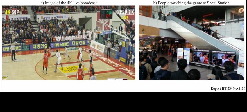
The detailed parameters of the 4K signal transmitted on the DTT platform are listed in Table 12. The
experimental broadcast chain of KBS, including content production, encoding, microwave link, is
shown in Fig. 36.You can also read