Cisco Meeting Server Cisco Meeting Server 2.8 and 2.9 - Installation Guide for Cisco Meeting Server 1000 and Virtualized Deployments
←
→
Page content transcription
If your browser does not render page correctly, please read the page content below
Cisco Meeting Server
Cisco Meeting Server 2.8 and 2.9
Installation Guide for Cisco Meeting Server 1000 and
Virtualized Deployments

April 22, 2021

                    Cisco Systems, Inc.   www.cisco.com
Contents
   Change History                                                                    4

   1 Introduction                                                                    5
      1.1 Overview of virtualized platforms                                          5
      1.2 How to use this Guide                                                      6
      1.3 Differences in specific MMP commands                                       8
      1.4 Differences in components enabled on the different platforms               8

   2 Installation                                                                   10
      2.1 Before You Start                                                          10
          2.1.1 About the Cisco Meeting Server software                             10
          2.1.2 Host requirements for the Cisco Meeting Server as a VM deployment   10
      2.2 Installing via VMware on a specification-based server                     13
      2.3 Deploying Meeting Server from the OVA file with ESXi 6.5 Web Client       14
      2.4 Installing and initial configuration of Cisco Meeting Server 1000         18
          2.4.1 Before You Start                                                    18
          2.4.2 Task 1 — Unpacking and initial startup                              18
          2.4.3 Task 2 — Configuring VMware Network Management                      20
          2.4.4 Task 3 — Configuring the VMware Instance using vSphere client       22
          2.4.5 Task 4 — Retrieving and activating VMware Licenses                  23
          2.4.6 Task 5 — Accessing the Cisco Meeting Server 1000 Console            24

   3 Configuration                                                                  25
      3.1 Creating your own Cisco Meeting Server Administrator Account              25
      3.2 Setting up the Network Interface for IPv4                                 25
      3.3 Adding Additional Network Interface(s)                                    27
      3.4 Configuring the Call Bridge                                               27
      3.5 Configuring the Web Admin Interface                                       28
          3.5.1 Creating the certificate for the Web Admin Interface                28
          3.5.2 Configuring the Web Admin Interface for HTTPS Access                30

   4 Getting and Entering a License File                                            32
      4.1 Transferring the license file to the Cisco Meeting Server                 32
      4.2 After transferring the license file                                       32

   Appendix A Technical specifications for Cisco Meeting Server 1000                34
      A.1 Physical specifications:                                                  34

Cisco Meeting Server 2.8 and 2.9 : Virtualized Deployments                           2
A.2 Environmental specifications                                         34
      A.3 Electrical specifications                                            34
      A.4 Video and audio specifications:                                      34

   Appendix B Cisco Licensing                                                  36
      B.1 Cisco Meeting Server Licensing and Activation Keys                   36
          B.1.1 Call Bridge Activation keys                                    36
          B.1.2 Recording                                                      37
          B.1.3 XMPP licenses                                                  37
      B.2 Cisco User Licensing                                                 37
          B.2.1 Personal Multiparty Plus Licensing                             38
          B.2.2 Shared Multiparty Plus Licensing                               38
          B.2.3 Cisco Meeting Server Capacity Units                            38
      B.3 How Cisco User Licenses are applied                                  39
      B.4 Setting up Cisco User Licensing                                      39

   Appendix C Branding                                                         40

   Appendix D Sizing a VM                                                      41
      D.1 Call Bridge VM                                                       43
      D.2 Edge VM                                                              44
      D.3 Database VM                                                          44
      D.4 Recorder and Streamer VM                                             44

   Appendix E Additional information on VMWare                                 46
      E.1 VMWare                                                               46

   Appendix F Creating a certificate signed by a local Certificate Authority   48

   Cisco Legal Information                                                     52

   Cisco Trademark                                                             53

Cisco Meeting Server 2.8 and 2.9 : Virtualized Deployments                      3
Change History

Change History
Date                          Change Summary

April 22, 2021                Added a note to Before you start about Smart Licensing.

December 09, 2020             Minor correction.

October 30, 2020              ESXi information updated. Title updated to include 2.9.

October 06, 2020              Minor corrections.

April 01, 2020                Broken links fixed.

November 27, 2019             400v/410v references removed.

November 13, 2019             Updated for version 2.8, ESXi support changes.

July 16, 2019                 Corrected documentation error, reinserted Installation chapter

May 30, 2019                  Minor documentation correction

April 26, 2019                Updated the supported versions of VMware ESXi

April 09, 2019                Miscellaneous corrections.

April 02, 2019                Information added for deploying Meeting Server from the OVA file with ESXi
                              6.5 Web Client.
                              Miscellaneous corrections.

January 28, 2019              Cisco Meeting Server 1000 using Cisco UCS C220 M5 Rack Server
                              supersedes the M4 variant. (From November 2018).

November 29, 2018             Miscellaneous corrections.

September 24, 2018            Removed Hyper-V section and references.

December 20, 2017             Added support for ESXi 6.5 and ESXi 6.0 Update 3 from Cisco Meeting Server
                              version 2.3.

November 27, 2017             Added Cisco Meeting Server 1000 additional installation detail. Removed
                              AWS references.

Cisco Meeting Server 2.8 and 2.9 : Virtualized Deployments                                                 4
1 Introduction

1 Introduction
The Cisco Meeting Server is a scalable software platform for voice, video and web content,
which integrates with a wide variety of third-party kit from Microsoft, Avaya and other vendors.
With the Cisco Meeting Server, people connect regardless of location, device, or technology.
The Cisco Meeting Server software runs as a virtualized deployment using VMware ESXi 6.x
with virtual hardware vmx-1x loaded onto the following platforms:
   l   Cisco Meeting Server 1000 (a preconfigured Cisco UCS C220 rack server. From early
       2019, the M5 variant superseded the M4 variant.)
   l   specification-based VM platforms.

The table below indicates the ESXi versions supported by the current versions of Cisco Meeting
Server software.

Table 1: ESXi version support

Cisco Meeting Server version               ESXi version

2.9                                        ESXi 7.0b with Virtual Hardware version 11
                                           ESXi 6.7 Update 3
                                           ESXi 6.5 Update 2
                                           ESXi 6.0 Update 3

2.8                                        ESXi 6.7
                                           ESXi 6.5 Update 2
                                           ESXi 6.0 Update 3

Customers often use virtualized deployments of the Cisco Meeting Server as the edge server in
a split deployment and in scalable deployments.
The functionality, and user experience for participants, is identical across all platforms running
the same software version. However, deployments are not interchangeable between the
virtualized deployments and physical deployments (Cisco Meeting Server 2000 and X-series
servers). For example, it is not possible to create a backup from a virtualized deployment and
roll it back on a Cisco Meeting Server 2000 or vice versa.

1.1 Overview of virtualized platforms

CAUTION: Irrespective of which virtualized platform is running the Cisco Meeting Server
software, ensure the platform is up to date with the latest patches. Failure to maintain the
platform may compromise the security of your Cisco Meeting Server.

Cisco Meeting Server 1000: ships with VMWare ESXi version 6.x and Cisco Meeting Server pre-
installed. However, this may not be the latest version of Cisco Meeting Server software

Cisco Meeting Server 2.8 and 2.9 : Virtualized Deployments                                           5
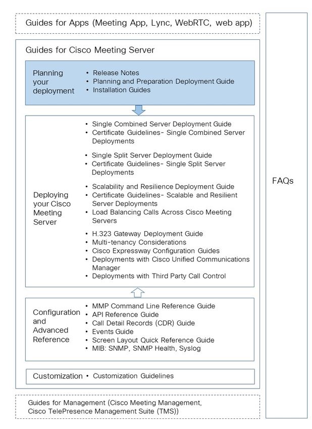
1 Introduction

available. Follow the instructions in this guide to configure the Cisco Meeting Server 1000 and
apply the license. Once the Cisco Meeting Server is operational, check the version of software
installed using the MMP command version. The latest software is available here. To upgrade
the software installed on the Cisco Meeting Server 1000, follow the instructions in the release
notes for that software version.

Note: If your Meeting Server ships with ESXi 6.x — the default Cisco UCS ESXi 6.x credentials for
the Cisco Meeting Server 1000 are: login as root with a password of password.
If your Meeting Server ships with ESXi 7.x — the default Cisco UCS ESXi 7.x credentials for the
Cisco Meeting Server 1000 are: login as root with a password of c!SCo123.

You are advised to change this login admin account. Be aware that when you change the
password, Cisco UCS ESXi will require a complex password.

specification-based VM platforms: if you are upgrading the server from a previous virtualized
Cisco Meeting Server installation, then follow the instructions in the Cisco Meeting Server
release notes. If this is a new installation, then follow this guide to create a VM and install the
Cisco Meeting Server software.

1.2 How to use this Guide
This guide covers the installation of the Cisco Meeting Server 1000 and specification-based VM
deployments.
The Cisco Meeting Server 1000 is shipped with the software pre-installed. Go to Section 2.4
before going to Chapter 3 of this guide to start configuring the Cisco Meeting Server 1000.

Note: The Cisco Meeting Server 1000 has different settings to the specification-based VM
server, the settings are pre-configured, do not change the settings.

If you are installing a specification-based VM deployment, then go to Chapter 2, before going
to Chapter 3 to configure the VM. Note that Chapter 2 is written for experienced VMware
administrators.
After configuring the Cisco Meeting Server and applying the license, use the Planning and
Preparation Deployment Guide to guide you on deciding the appropriate deployment, and then
follow the deployment and certificate guides that are most relevant to your targeted
deployment, see Figure 1. These documents can be found on cisco.com.

Cisco Meeting Server 2.8 and 2.9 : Virtualized Deployments                                            6

1 Introduction

Figure 1: Cisco Meeting Server installation and deployment documentation

Cisco Meeting Server 2.8 and 2.9 : Virtualized Deployments                              7

1 Introduction

Note: The address ranges we use in Cisco user documentation are those defined in RFC 5737
which are explicitly reserved for documentation purposes. IP addresses in Meeting Server user
documentation should be replaced with correct IP addresses routable in your network, unless
otherwise stated.

1.3 Differences in specific MMP commands
The MMP Command Reference details the full set of MMP commands. There are a few
differences running a Cisco Meeting Server 2000 compared to a virtualized Cisco Meeting
Server or Acano X-Series server.

                                                     on Cisco Meeting Server
                        on Cisco Meeting Server      1000 and virtualized Cisco
Command                 2000                         Meeting Server               on Acano X-Series server

shutdown                Not available through        Do not use the vSphere       Enter “Y” when prompted.
                        MMP. Use Cisco UCS Man-      power button. Use the        The server can now be
                        ager to power down blade     shutdown command             safely powered off.
                        servers before removing      instead.
                        power.

health                  Not available through   Not available                     Returns health of server.
                        MMP. Use Cisco UCS Man-
                        ager.

serial                  Returns serial number of     Not available                Returns serial number of
                        server.                                                   server.

dns                     Do not specify an            Do not specify an inter-     Must specify an
                        interface.                   face.                        interface,use either mmp
                                                                                  or app. For example
                        For example                  For example
                                                                                  dns mmp add
                        dns add                      dns add
                                                                                  forwardzone
                        forwardzone                  forwardzone

user evict              Not available                Available                    Available
                        Available from version 2.9

1.4 Differences in components enabled on the different platforms
The table below list the components available on the different Cisco Meeting Server platforms.
If a component is not available on a platform, then the MMP and API commands specific to the
component will not be available. For instance, the MMP and API commands for the TURN Server
are not available on the Cisco Meeting Server 2000.

Cisco Meeting Server 2.8 and 2.9 : Virtualized Deployments                                                    8
1 Introduction

                                                    on Cisco Meeting Server
                          on Cisco Meeting Server   1000 and virtualized      on Acano X-Series
Component                 2000                      Cisco Meeting Server      server

Call Bridge               Available                 Available                 Available

Web Bridge                Available                 Available                 Available

XMPP Server               Available                 Available                 Available

Database                  Available                 Available                 Available

TURN server               Not available             Available                 Available

Load balancer             Not available             Available                 Available

Recorder                  Not available             Available                 Available

Uploader                  Not available             Available                 Available

Streamer                  Not available             Available                 Available

H.323 Gateway             Not available             Available                 Available

SNMP MIB                  Not currently available   Available                 Available.

Cisco Meeting Server 2.8 and 2.9 : Virtualized Deployments                                              9
2 Installation

2 Installation
This chapter applies to deployments on specification-based VM platforms and Cisco Meeting
Server 1000. Follow Section 2.2 to deploy a VMware host. Follow Section 2.4 to deploy a
Cisco Meeting Server 1000.

2.1 Before You Start

2.1.1 About the Cisco Meeting Server software
The Cisco Meeting Server software is provided as an .ova file for VMware users. This is a
template that sets up a new VM with a single network interface and a virtual disk containing the
Cisco Meeting Server application.
After installation a fully functioning Cisco Meeting Server is available, which can be run as:
n   a complete solution with all components enabled on a single server (single combined server
    deployment model),
n   a split deployment with some components enabled on a Core server deployed on the internal
    network, and other components enabled on an Edge server deployed in the DMZ (single split
    server deployment model),
n   a scalable and resilient deployment with multiple Call Bridges and databases, clustered
    together to support growth in usage and minimize downtime.

The same .ova file is used to install all deployments.
To upgrade the Cisco Meeting Server software follow the procedure in the release notes
published for the software version.

Note: To avoid issues with Smart Licensing from 3.0 onwards where Meeting Management is
required, install a new Meeting Server every time instead of cloning the Meeting Server. Or, do a
full factory reset to be able to reassign a new identical host id for the VM Meeting Servers that
are already cloned.

2.1.2 Host requirements for the Cisco Meeting Server as a VM deployment
The Cisco Meeting Server runs on a broad range of standard Cisco servers as a VM
deployment. Refer to this link for VM configuration requirements and UCS tested reference
configurations for different deployments.
The Cisco Meeting Server also runs on third party servers including systems from Dell and HP
containing both Intel and AMD processors. Small form factor and ruggedized systems such as

Cisco Meeting Server 2.8 and 2.9 : Virtualized Deployments                                         10
2 Installation
Klas VoyagerVM and DTECH LABS M3-SE-SVR2 are also supported. The software can be
deployed on VMware ESXi as well as cloud services.
Table 2: Host requirements for the Cisco Meeting Server running on third party servers
Minimum Recommended
Server manufacturer Any Any
Processor type Intel Nehalem Intel Xeon 2600 v2 or newer
microarchitecture
AMD Bulldozer
microarchitecture
Processor frequency 2.0GHz 2.5Ghz
RAM 1GB per logical 1GB per logical core*
core*
Storage 100GB 100GB
Hypervisor Latest update of Latest update of VMware ESXi 6.7 with virtual hardware
VMware ESXi 6.0 vmx-14
with virtual hardware
vmx-11 Note: Refer to the VMware documentation for further
information.
Hypervisor Latest update of Latest update of VMware ESXi 6.7 with virtual hardware
VMware ESXi 6.5 vmx-14
with virtual hardware
vmx-13 Note: Refer to the VMware documentation for further
information.
* additional memory should be available on the system for use by the hypervisor and any other VMs on the host.
Note: Meeting Server supports single and dual socket servers only.
Note: Both ESXi 6.5 and ESX 6.0 Update 3 provide a tool to enable you to disable TLS1.0 and
TLS 1.1 from communicating with ESXi.
Table 3: Recommended Core VM configurations
720p30 call legs CPU configuration RAM configuration Example systems
50 Dual Intel E5-2680v2 32 GB (8x4GB) Cisco UCS C220 M3
Dell R620
HP DL380p Gen8
Cisco Meeting Server 2.8 and 2.9 : Virtualized Deployments 112 Installation
720p30 call legs CPU configuration RAM configuration Example systems
40 Dual Intel E5-2650v2 32 GB (8x4GB) Cisco UCS C220 M3
Dell R620
HP DL380p Gen8
25 Single Intel E5-2680v2 16 GB (4x4GB) Cisco UCS C220 M3
Dell R620
HP DL380p Gen8
15 Single Intel E5-2640v2 8 GB (4x2GB) Cisco UCS C220 M3
Dell R620
HP DL380p Gen8
Cisco Meeting Server 2.8 and 2.9 : Virtualized Deployments 122 Installation
In addition:
n All memory channels should be populated to maximize available memory bandwidth. There
are no special requirements for NUMA systems.
n Out-of-band management systems should not be configured to share a network port with
the VM. Internal testing has shown that they can cause bursts of packet loss and degraded
voice and video quality. Out-of-band management should either be configured to use a
dedicated network port or disabled.
n Where available, hyperthreading should be enabled on the host, without this there is capacity
reduction of up to 30%.
n When comparing AMD and Intel processors, the number of AMD “Modules” (a pair of “cores”
sharing resources) should be compared to Intel “cores” (which execute a pair of
“hyperthreads”). In internal testing we have found that AMD processors provide 60-70%
capacity of an equivalent Intel processor. For this reason Intel processors are recommended
for production deployments.
n The CPUs used by the Cisco Meeting Server must be dedicated for its use. This is achieved
by:
o only running a single VM on the host, or
o pinning of all VMs on the host to specific cores and giving the Cisco Meeting Server sole
use of the assigned cores, and in addition, leaving a physical core with no VMs pinned to it
for the Hypervisor.
o following the co-residency requirements for Unified Communication in a Virtualized
Environment. Click on Cisco Meeting Server below the Meeting heading.
n If a VMWare Hypervisor with EVC mode enabled is used, the EVC must be set to one of the
following modes or higher:
“B1”/AMD Opteron™ Generation 4
“L2”/Intel® Nehalem generation (formerly Intel® Xeon Core™ i7)
EVC modes which enforce compatibility with older CPUs than those listed above, are not
supported as they will disable SSE 4.2; SSE4.2 is required.
n An activation key for the Call Bridge is required for media calls. To obtain the activation key,
you need the MAC address of your virtual server. See Chapter 4 and for information on
licensing.
2.2 Installing via VMware on a specification-based server
Note: For every release of the Cisco Meeting Server for virtualized deployments, there will be an
.ova file for a new deployment, and an upgrade image (.img) for upgrading to the latest release.
This differs from the Acano Server releases which provided an ovf folder and associated files.
Cisco Meeting Server 2.8 and 2.9 : Virtualized Deployments 132 Installation
For a new installation follow this section; for an upgrade follow the release notes.
l If a VMWare Hypervisor with EVC mode enabled is used, the EVC must be set to one of the
following modes or higher:
“B1”/AMD Opteron™ Generation 4
“L2”/Intel® Nehalem generation (formerly Intel® Xeon Core™ i7)
EVC modes which enforce compatibility with older CPUs than those listed above, are not
supported as they will disable SSE 4.2; SSE4.2 is required.
l An activation key for the Call Bridge is required for media calls. To obtain the activation
key, you need the MAC address of your virtual server. See Chapter 4 and for information
on licensing.
2.3 Deploying Meeting Server from the OVA file with ESXi 6.5 Web Client
Note: For every release of the Cisco Meeting Server for virtualized deployments, there will be an
.ova file for a new deployment, and an upgrade image (.img) for upgrading to the latest release.
This differs from the Acano Server releases which provided an ovf folder and associated files.
For a new installation follow this section; for an upgrade follow the release notes.
1. Download the .ova file from the Cisco web site.
2. In the vSphere Client go to the host in the Navigator tab on the left and select
Create/Register VM.
3. For Select creation type, select Deploy a virtual machine from an OVF or OVA file and click
Next.
Cisco Meeting Server 2.8 and 2.9 : Virtualized Deployments 142 Installation
4. Enter the desired name for the virtual machine and browse or drop the .ova file (downloaded
in step 1) to select it.
5. Follow the wizard instructions. The settings that must be selected are:
a. Select the datastore to store the VM configuration and disk files.
b. Select the network mapping you would like the VM to be connected to.
c. Set Disk provisioning to Thick.
d. Ensure Power On After Deployment is not selected.
e. Click Finish.
Note: Depending on how your virtual host is set up, some of the wizard settings may not
be displayed or may not be selectable.
Cisco Meeting Server 2.8 and 2.9 : Virtualized Deployments 152 Installation
6. Once completed, the new Cisco Meeting Server VM should now be listed in your Virtual
Machines.
7. Select the Cisco Meeting Server VM from your list of VMs.
8. From the Actions button, select Edit Settings….
a. Edit VM settings and choose CPUs. Set Number of CPUs to the desired number (where 4
is the minimum). See the deployment guide for scaling details. For more information on
VM configuration requirements, see
https://www.cisco.com/c/dam/en/us/td/docs/voice_ip_comm/uc_
system/virtualization/virtualization-cisco-meeting-server.html and Appendix D.
b. Set Number of Cores per Socket to one of the following:
l On a dual processor host with hyperthreading, set Number of Cores per Socket to the
number of logical cores minus 2.
l On a dual processor host without hyperthreading, set Number of Cores per Socket to
the number of logical cores minus 1.
l On a single processor host, set Number of Cores per Socket to the number of logical
cores.
We recommend that you configure the number of sockets to mirror underlying
hardware.
Note: The number of logical cores can be found on the vSphere Web Client, by clicking
Manage > Settings > Processors. For more information, see:
https://docs.vmware.com/en/VMware-
vSphere/6.5/com.vmware.vsphere.resmgmt.doc/GUID-E09F36DF-E31F-417D-
9865-06E351D8AF15.html
Cisco Meeting Server 2.8 and 2.9 : Virtualized Deployments 162 Installation
c. Ensure the RAM is set to a minimum of 4GB and the disk space is set to 100GB.
9. Click Power on.
10. Click the Console tab and open the browser console (or remote console if VMware Remote
Console is installed).
Cisco Meeting Server 2.8 and 2.9 : Virtualized Deployments 172 Installation
11. Log in with the user name “admin” and the password “admin”. You will be asked to change
the admin password. You are now logged into the MMP. Go on to Chapter 3.
2.4 Installing and initial configuration of Cisco Meeting Server 1000
2.4.1 Before You Start
You need the following to complete your installation:
l PAK license number
l VMware license activation codes or customer-supplied VMware license keys
l Internet and email access to complete the license retrieval steps
l A Windows computer running vSphere Client 6.0 or the permisssions to install vSphere
client on the computer
l A console, either:
l A monitor with a VGA connector and USB keyboard
or
l A PC with a serial adaptor, Cisco serial cable, and terminal program, and network
connection with Internet Explorer or Firefox with JAVA installed and enabled
2.4.2 Task 1 — Unpacking and initial startup
1. Unpack the Meeting Server, power cords, console adaptor, and rack kit.
2. Position the Meeting Server or optionally rackmount — see the Cisco UCS C220 M5
Installation Guide or Cisco UCS C220 M4 Installation Guide, as appropriate for your
deployment.
3. Connect the Ethernet cables to the Ethernet1 port on the rear of the Meeting Server and
connect to the Ethernet network.
4. Connect the power cords to each power supply and connect to power.
Cisco Meeting Server 2.8 and 2.9 : Virtualized Deployments 182 Installation
5. Press the power button on the front of the Meeting Server. It will automatically stop and
restart itself more than once after initial power on.
6. Connect a console to the Meeting Server to continue. You can use either a monitor and
keyboard, or use a virtual console over a network connection. Select from the following
options:
2.4.2.1 Console Option 1 — Monitor and keyboard
1. Attach a monitor with a VGA connection to the VGA port on the rear of the Meeting
Server, or to the console port on the front.
2. Connect a keyboard to the USB ports located on the rear of the Meeting Server, or to the
console port on the front.
The Meeting Server will automatically boot to the VMware console screen when startup is
complete and should be visible on the monitor.
2.4.2.2 Console Option 2 — Virtual console over network
Use this method if no monitor and keyboard are available to connect to the Meeting Server:
1. Connect your computer's serial port to the RJ-45 port on the rear of the Meeting Server
labeled 10101 using the standard blue Cisco RJ-45 to DB-9 Null Serial cable provided
with routers and switches.
2. Open your terminal program, select the COM port for your serial port/adaptor and set the
terminal settings to 115200 baud, No Parity, 8 data bits, 1 stop bit.
3. Connect a second Ethernet LAN port to the RJ-45 port on the rear of the Meeting Server
labeled M1. If you only have the resources for one network connection, remove the LAN
connected to Ethernet1 and use it for the M1 port temporarily to enable the virtual
console, and move it back to Ethernet1 after configuration. The M1 port must be
connected and configured with a valid IP address to use the virtual console.
4. Ensure Meeting Server has its power supplies connected. If not, ensure it has been
plugged in for several minutes to allow the CIMC management interface to startup.
Meeting Server does not have to be powered on for CIMC to function, but must be
connected to power. (There is no external indicator for CIMC status.)
5. In your terminal program, press Escape and the 9 keys simultaneously to switch the port to
CIMC. A username prompt displays.
6. Enter the default username and password (username: admin, password: password).
7. The first time you login, you will be prompted to change the password to one of your
choice. Complete the prompts to set a new password.
8. Once logged in, at the command prompt enter the command scope cimc — the
command prompt changes to reflect that you are now in the CIMC menu.
Cisco Meeting Server 2.8 and 2.9 : Virtualized Deployments 192 Installation
9. Enter the command show network detail to show the current configuration of the
management Ethernet interface, including the current IP address the server has aquired via
DHCP (if available on the network). Make a note of the IPv4 address shown (if DHCP is
available).
10. If DHCP is not available and you need to set a static IP, use the following commands,
changing the sample values to ones appropriate for your network. (These commands
assume you are already in the CIMC scope.)
scope network
set dns-use-dhcp no
set dhcp-enabled no
set v4-addr 10.1.2.3
set v4-netmask 255.255.255.0
set v4-gateway 10.1.2.1
commit
11. Enter show network detail to confirm your changes. Once complete, enter the
command exit twice to log out of the CIMC.
12. Switch to your PC's browser, and browse to the IP address you configured or obtained
from the CIMC serial interface. Dismiss the certificate security warnings and a Cisco
landing page with username and password fields will display.
13. Login with the username of admin and the password you set when first connecting to the
CIMC.
14. When the Server Summary page loads, click the Launch KVM Console link under Actions.
The JAVA virtual console application loads. Depending on your Operating System and
browser you may get security warnings and dialogs to acknowledge and accept. Continue
until the application loads—it will show the monitor image as if you were directly connected
to the server. If the server is powered off, it will show a larger green window saying No
Signal.
15. If the server is powered off, from the Power menu, select Power On to start the server.
After a few minutes it should boot to the VMware console screen.
You can now use the virtual console the same as if you were connected using a local monitor
and keyboard.
2.4.3 Task 2 — Configuring VMware Network Management
You must have console access to the server via monitor or virtual console to complete the
following steps.
Ensure the server is powered on and the VMware console screen displays, offering press F2 to
configure or F12 to shutdown.
Cisco Meeting Server 2.8 and 2.9 : Virtualized Deployments 202 Installation
1. Press F2 to configure the server. The default username is root and the default password
is dependent up the version of ESXi installed, i.e. if your Meeting Server 1000 ships with
ESXi 6.x the default password is password, if it ships with ESXi 7.x the default password
is c!SCo123.
2. We recommend you change the default password:
a. From the menu options, use the arrow and Enter keys to select Configure Password.
b. Follow the prompts and set a password to use for the VMware root account.
Note: VMware has high password complexity requirements— use a strong password
including special characters, mixed case, and alpha and numeric characters.
3. From the menu options, use the arrow and Enter keys and select Configure Management
Network and then IPv4 Configuration.
4. Select the option for the network configuration you will use (DHCP or Static IP
assignment) and configure the IPv4 Address, Mask, and Gateway as appropriate for your
network.
REMINDER: This IP address is for the VMware Hypervisior, not the Meeting Server
application. The address used must be unique from the Meeting Server application.
5. (Optional) If you will access the Hypervisor management via a different VLAN from the
Meeting Server application, configure the VLAN that the Management Interface should
associate with.
6. Press Escape to return to the main menu, and Escape again to log out.
The VMware management IP address displays in the bottom left of the screen.
2.4.3.1 Useful information if you are using the virtual console
l CIMC is a powerful out-of-band management interface for the Meeting Server and is
recommended for use when the Meeting Server is installed in a rack or computer room.
This management interface is not used by VMware or the Meeting Server application, so if
you want to keep it connected, you must secure a dedicated LAN connection for the M1
Ethernet port. (NIC sharing options are also available in the Cisco UCS Server
documentation.)
l If you are using the virtual console with only one network connection and had been
temporarily using it for the M1 interface:
a. You will not need the virtual console anymore to complete the install. Disconnect the
Ethernet cable from the M1 interface of the server and reconnect it to the Ethernet1
port.
b. If you are using DHCP for the VMware management interface, you will need to restart
the server to obtain a new IP address after connecting the Ethernet cable. To restart,
press the power button on the front of the server briefly and the server will initiate an
Cisco Meeting Server 2.8 and 2.9 : Virtualized Deployments 212 Installation
automatic shutdown (this takes several minutes). After it powers off, power it back
on using the power button. Because you disconnected the network that the virtual
console was using, you will not be able to see the IP address the server obtained. To
find the IP address, contact your DHCP administrator to find which IP address the
server was assigned. The MAC address of the Ethernet1 interface can be found on
the pull-out tab located on the front of the Cisco Meeting Server 1000.
You should now have Ethernet connected to the Ethernet1 port on the rear of the server and
know the IP address in use by the VMware management network.
2.4.4 Task 3 — Configuring the VMware Instance using vSphere client
Now you connect to the VMware instance and complete the Hypervisor's initial configuration.
1. If you do not have vSphere 6.0 or 6.5 client installed and need to install it, follow these
steps:
a. Download from the local VMware instance:
i. Using your Internet Browser, browse to your new server's IP, for example,
http://IPaddress
ii. Click the link for Browse database in this host's inventory
iii. Enter the username root and password you configured in the VMware
network management setup.
iv. Navigate to datastore1\OVA-ISO\VMware\ and click the VMware-viclient...
link to download the client installer.
v. Once downloaded, locate the file and run the program to install the vSphere
client.
2. Open vSphere client and in the connection window, enter the IP for your VMware instance,
the username root and the password created during the VMware network management
configuration. Click Login to connect to the server.
3. An SSL certificate warning appears when connecting to the server, click Ignore to
continue. Upon connecting, you will also get a VMware evaluation notice, click OK.
2.4.4.1 Configuring VMware NTP
Configure the Hypervisor to have a valid NTP source so its logs will be accurate:
1. In the vSphere client, connect to the Meeting Server, and click on the Meeting Server in the
left panel to select it.
2. In the right-hand panel, click the Configuration tab, and under Software, click Time
Configuration.
3. In the resulting page, click the Properties link (in the top right corner).
Cisco Meeting Server 2.8 and 2.9 : Virtualized Deployments 222 Installation
4. In the Properties window, check the NTP Client Enabled checkbox and click the Options
button.
5. Click NTP Settings from the list and click the Add button to add the NTP source(s) you
wish to use.
6. Select General from the list.
7. Change the Service to Start and Stop with the host.
8. Click Start to start the service.
9. Click OK twice to close the time configuration pages.
2.4.5 Task 4 — Retrieving and activating VMware Licenses
If you ordered VMware licenses from Cisco, the licenses will be delivered as Activation Codes in
separate packaging or emails from Cisco. You require two 1-CPU licenses per Cisco Meeting
Server1000. These activation codes must be converted to license keys using the VMware public
website. You need internet and email access to complete this task.
2.4.5.1 Activate VMware activation keys
1. Use an internet browser (we recommend a browser other than Google Chrome for this
task), go to https://www.vmware.com/oem/code.do?Name=CISCO-RESELL-AC
2. Login with a VMware account. If you do not have one, complete the steps provided on the
webpage to create a new VMware profile.
3. Once logged in, enter the activation codes following your organization's policy on
assigning software activation codes. After completing the steps, VMware will email the
license codes to you.
4. Once the licenses have been added to your VMware account, the two single CPU licenses
must be combined into a single, dual CPU license. This is achieved on the myVMware
portal. These steps are covered in detail on the VMware KB article:
https://kb.vmware.com/s/article/2006973.
TIP: You may have issues combining licenses immediately after adding them into your
VMware profile. If this happens, wait 5-10 minutes and try again. If you continue to have
issues, contact VMware licensing support to assist with combining the licenses.
5. Once you have the new combined license key, open the vSphere client, connect to the
Meeting Server if you are not already, and click on the Meeting Server in the tree in the left
panel.
6. In the right panel, select the Configuration tab, then under Software, click on Licensed
Features.
7. Current evaluation details display, click on the Edit link at the top right corner of the page.
Cisco Meeting Server 2.8 and 2.9 : Virtualized Deployments 232 Installation
8. In the resulting window, select Assign a new key to this host and click the Enter button to
enter your license key.
9. Click OK close the dialog window.
Hypervisor basic setup is now complete.
2.4.6 Task 5 — Accessing the Cisco Meeting Server 1000 Console
The Meeting Server instance itself can be accessed by connecting to its own IP address, or via
the vSphere client console function.
1. Open the vSphere client and log into your Meeting Server's IP address with the username
of root and the password you configured previously.
2. Select the Meeting Server from the left-hand panel, and use the plus sign (+) to expand
the tree. A virtual machine named Cisco Meeting Server will be present and a green arrow
to indicate it is powered on.
3. If your network has DHCP, to find the current Meeting Server IP address, click on the
Summary tab while the Cisco Meeting Server VM is highlighted. The IP address the
Meeting Server has obtained will be shown under the General section. You can ssh to that
IP to continue the configuration of the Meeting Server software.
4. If your network does not have DHCP, you will have to assign an IP address to the VM using
the virtual machine console in the vSphere client and the Meeting Server MMP commands
ipv4 or ipv6 as described in Chapter 3 (or see the MMP Command Line Reference
Guide).
5. To access the console, click on the Console tab in the vSphere client when the Meeting
Server VM is selected. If the screen is blank, click within the window and press the Enter
key. A login prompt displays.
TIP: To regain mouse control outside the console window, press the Control and Alt keys
together.
6. Log in with the user name “admin” and the password “admin”. You will be asked to change
the admin password.
CAUTION: Passwords expire after 6 months.
The rest of the configuration process follows that described in Chapter 3.
Cisco Meeting Server 2.8 and 2.9 : Virtualized Deployments 243 Configuration
3 Configuration
3.1 Creating your own Cisco Meeting Server Administrator Account
For security purposes, you are advised to create your own administrator accounts as username
“admin” is not very secure. In addition, it is good practice to have two admin accounts in case
you lose the password for one account, if you do, then you can still log in with the other account
and reset the lost password.
Use the MMP command user add admin, see the MMP Command Reference Guide
for details. You will be prompted for a password which you must enter twice. Login with the
new account, you will be asked to change the password.
CAUTION: Passwords expire after 6 months.
After creating your new admin accounts delete the default “admin” account.
Note: Any MMP user account at the admin level can also be used to log into the Web Admin
Interface of the Call Bridge. You cannot create users through the Web Admin Interface.
3.2 Setting up the Network Interface for IPv4
Note: Although these steps are for IPv4, there are equivalent commands for IPv6. See the MMP
Command Reference for a full description.
In the Cisco Meeting Server virtualized deployment, there is only one network interface initially,
interface “a”, but up to 4 are supported (see the next section). The initial interface is “a”,
equivalent to interface A on the Acano X-Series server. The MMP runs on interface a in the
virtual deployment.
1. To set network interface speed, duplex and auto-negotiation parameters use the iface
MMP command e.g. to display the current configuration on the "a" interface, in the MMP
type:
iface a
a. Set the network interface speed (Mbps), duplex and auto negotiation parameters
using the command iface (admin|a|b|c|d) (full|on|off). For
example, set the interface to 1GE, full duplex:
iface a 1000 full
Cisco Meeting Server 2.8 and 2.9 : Virtualized Deployments 253 Configuration
b. Switch auto negotiation on or off using the command iface a autoneg
. For example:
iface a autoneg on
Note: We recommend that the network interface is set to auto negotiation "on" unless
you have a specific reason not to.
2. The “a” interface is initially configured to use DHCP. To view the existing configuration, type:
ipv4 a
a. If you are using DHCP IP assignment, no further IP configuration is needed, go to step 3.
b. If you are using Static IP assignment:
Use the ipv4 add command to add a static IP address to the interface with a specified
subnet mask and default gateway.
For example, to add address 10.1.2.4 with prefix length 16 (netmask 255.255.0.0) with
gateway 10.1.1.1 to the interface, type:
ipv4 a add 10.1.2.4/16 10.1.1.1
To remove the IPv4 address, type:
ipv4 a del
3. Set DNS Configuration
Meeting Server requires DNS lookups for many of its activities including looking up SRV
records and is required for a simplified deployment. We recommend you point Meeting
Server to the default DNS resolver for your network using a period "." for the forwardzone
value.
a. To output the dns configuration, type:
dns
b. To set the application DNS server use the command:
dns add forwardzone
Note: A forward zone is a pair consisting of a domain name and a server address: if a
name is below the given domain name in the DNS hierarchy, then the DNS resolver can
query the given server. Multiple servers can be given for any particular domain name to
provide load balancing and fail over. A common usage will be to specify "." as the
domain name i.e. the root of the DNS hierarchy which matches every domain name.
for example:
dns add forwardzone . 10.1.1.33
c. If you need to delete a DNS entry use the command:
Cisco Meeting Server 2.8 and 2.9 : Virtualized Deployments 263 Configuration
dns del forwardzone
for example:
dns del forwardzone . 10.1.1.33
3.3 Adding Additional Network Interface(s)
The Cisco Meeting Server virtualized deployments support up to four interfaces (a, b, c and d).
If required, you can add a second network interface on VMWare. However, any two interfaces of
the Cisco Meeting Server must not be put into the same subnet.
1. In the vSphere Client, locate your VM in the Hosts and Clusters list
2. Select Edit Virtual Machine Settings.
3. Add a Network Adapter with type VMXNET3.
Note: If you select an Ethernet Adaptor which is not VMXNET3, then you may experience
network connection problems, and may invalidate your license.
Note: For more information on adding or modifying Ethernet Adapters, refer to the VMware
web page Adding and Modifying Virtual Network Adapters.
4. After adding the new adapter, enable the interface for use on the MMP with the command
ipv4 b enable, for example.
5. Reboot the VM so the addresses and gateway can be added manually or automatically
picked up by DHCP (if enabled for that interface).
3.4 Configuring the Call Bridge
The Call Bridge needs a key and certificate pair that is used to establish TLS connections with
SIP Call Control devices and with the Lync Front End (FE) server. If you are using Lync, this
certificate will need to be trusted by the Lync FE server.
The command callbridge listen allows you to configure a listening interface
(chosen from A, B, C or D). By default the Call Bridge listens on no interfaces.
1. Create and upload the certificate as described in the Certificate Guidelines.
2. Sign into the MMP and configure the Call Bridge to listen on interface A.
callbridge listen a
Cisco Meeting Server 2.8 and 2.9 : Virtualized Deployments 273 Configuration Note: the Call Bridge must be listening on a network interface that is not NAT’d to another IP address. This is because the Call Bridge is required to convey the same IP that is configured on the interface in SIP messages when talking to a remote site. 3. Configure the Call Bridge to use the certificates by using the following command so that a TLS connection can be established between the Lync FE server and the Call Bridge, for example: callbridge certs callbridge.key callbridge.crt The full command and using a certificate bundle as provided by your CA, is described in the Certificate Guidelines. 4. Restart the Call Bridge interface to apply the changes. callbridge restart 3.5 Configuring the Web Admin Interface The Web Admin Interface acts as the interface to the Call Bridge; the API of the Cisco Meeting Server is routed through this web interface. Configuring the Web Admin Interface involves creating a private key/certificate pair, see Section 3.5.1, and uploading the private key/certificate pair to the MMP, see Section 3.5.2. Once the Web Admin Interface is enabled you can use either the API or the Web Admin to configure the Call Bridge. 3.5.1 Creating the certificate for the Web Admin Interface The Web Admin Interface is only accessible through HTTPS, you need to create a security certificate and install it on the Cisco Meeting Server. Follow the steps described in the Certificate Guidelines for a production environment — this section shows how to test with a self- signed certificate in a lab environment. Note: You need a certificate uploaded for the Web Admin Interface even if you configure the Call Bridge through the API rather than the Web Admin Interface. The information below assumes that you trust Cisco to meet requirements for the generation of private key material. If you prefer, you can generate the private key and the certificate externally using a public Certificate Authority (CA), and then load the externally generated key/certificate pair onto the MMP of the Cisco Meeting Server using SFTP. After obtaining the signed certificate, go to Section 3.5.2. Note: If testing your Cisco Meeting Server in a lab environment, you can generate a key and a self-signed certificate on the server. To create a self-signed certificate and private key, log in to Cisco Meeting Server 2.8 and 2.9 : Virtualized Deployments 28
3 Configuration

the MMP and use the command:
pki selfsigned
where  identifies the key and certificate which will be generated e.g. "pki
selfsigned webadmin" creates webadmin.key and webadmin.crt (which is self-signed). Self-
signed certificates are not recommended for use in production deployments.

The steps below explain how to generate a private key and the associated Certificate Signing
Request using the MMP command pki csr , and export them for signing by a CA.
1. Log in to the MMP and generate the private key and certificate signing request (CSR):
    pki csr  [:]
    where:
     is a string identifying the new key and CSR (e.g. "webadmin" results
    in "webadmin.key" and "webadmin.csr" files)
    and the allowed, but optional attributes are as follows and must be separated by a colon:
    l   CN: the commonName which should be on the certificate. Use the FQDN defined in DNS
        A record as the Common Name. Failure to do this will result in browser certificate errors.
    l   OU: Organizational Unit
    l   O: Organization
    l   L: Locality
    l   ST: State
    l   C: Country
    l   emailAddress
    Use quotes for values that are more than one word long, for example:
    pki csr example CN:example.com "OU:Accounts UK" "O:My Company"
2. Send the CSR to one of the following:
    l   To a Certificate Authority (CA), such as Verisign who will verify the identity of the
        requestor and issue a signed certificate.
    l   To a local or organizational Certificate Authority, such as an Active Directory server with
        the Active Directory Certificate Services Role installed, see Appendix F.

Note: Before transferring the signed certificate and the private key to the Cisco Meeting Server,
check the certificate file. If the CA has issued you a chain of certificates, you will need to extract
the certificate from the chain. Open the certificate file and copy the specific certificate text
including the BEGIN CERTIFICATE and END CERTIFICATE lines and paste into a text file. Save the
file as your certificate with a .crt, .cer or .pem extension. Copy and paste the remaining
certificate chain into a separate file, naming it clearly so you recognize it as an intermediate

Cisco Meeting Server 2.8 and 2.9 : Virtualized Deployments                                         29
3 Configuration certificate chain and using the same extension ( .crt, .cer or .pem). The intermediate certificate chain needs to be in sequence, with the certificate of the CA that issued the chain first, and the certificate of the root CA as the last in the chain. 3.5.2 Configuring the Web Admin Interface for HTTPS Access Note: The deployment automatically sets up the Web Admin Interface to use port 443 on interface A. However, the Web Bridge also uses TCP port 443. If both the Web Admin Interface and the Web Bridge use the same interface, then you need to change the port for the Web Admin Interface to a non-standard port such as 445, use the MMP command webadmin listen . 1. Establish an SSH connection to the MMP and sign in. 2. Use SFTP to upload the private key/certificate pair and certificate bundle (optional) for the Web Admin Interface. 3. Disable the Web Admin Interface before assigning the certificate. webadmin disable 4. Assign the private key/certificate pair you uploaded in step 2, using the command: webadmin certs [] where keyfile and certificatefile are the filenames of the matching private key and certificate. If your CA provides a certificate bundle then also include the bundle as a separate file to the certificate. For example: webadmin certs webadmin.key webadmin.crt webadminbundle.crt 5. Restart the Web Admin Interface. webadmin restart 6. Enable the Web Admin Interface. webadmin enable For example: webadmin certs webadmin.key webadmin.crt webadmin listen b 443 webadmin restart webadmin enable Test that you can access the Web Admin Interface, i.e. enter your equivalent of https://cms- server.mycompany.com (or the IP address) in your browser and login using the MMP user account you created earlier. The banner shown in Figure 2 below will be displayed until a cms.lic license file is uploaded. Cisco Meeting Server 2.8 and 2.9 : Virtualized Deployments 30
3 Configuration

Figure 2: Cisco Meeting Server in Evaluation Mode

After you upload and apply the license file, the banner is removed. However, before you can
apply the license you need to configure the port that the Call Bridge will listen on, and upload the
Call Bridge certificates. This is described in the deployment guides as the type of certificates
required for the Call Bridge is determined by your deployment.
Refer to Section 4 for information on obtaining and applying a license file, after the Call Bridge
has been configured.

Cisco Meeting Server 2.8 and 2.9 : Virtualized Deployments                                       31
4 Getting and Entering a License File

4 Getting and Entering a License File
All virtualized deployments of the Cisco Meeting Server require a license file; the license file is for
the MAC address of your virtual server.
describes the Cisco Licensing available to purchase for the Cisco Meeting Server. After
purchasing the licensing, follow this chapter to apply the license to the Cisco Meeting Server.

4.1 Transferring the license file to the Cisco Meeting Server
This section assumes that you have already purchased the licenses that will be required for your
Meeting Server from your Cisco Partner and you have received your PAK code(s).
Follow these steps to register the PAK code with the MAC address of your Meeting Server using
the Cisco License Registration Portal.
1. Obtain the MAC address of your Meeting Server by logging in to the MMP of your server,
   and enter the MMP command: iface a

   Note: This is the MAC address of your VM, not the MAC address of the server platform that
   the VM is installed on.

2. Open the Cisco License Registration Portal and register the PAK code(s) and the MAC
   address of your Meeting Server.
3. If your PAK does not have an R-CMS-K9 activation license, you will need this PAK in addition
   to your feature licenses.
4. The license portal will email a zipped copy of the license file. Extract the zip file and rename
   the resulting xxxxx.lic file to cms.lic.
5. Using your SFTP client, log into Meeting Server and copy the cms.lic file to the Meeting
   Server file system.
6. Restart the Call Bridge using the MMP command callbridge restart
7. After restarting the Call Bridge, check the license status by entering the MMP command
   license
   The activated features and expirations will be displayed.

4.2 After transferring the license file
To apply the license you need to restart the Call Bridge. However, you must have configured the
Call Bridge certificates and a port on which the Call Bridge listens, before you can do this.
After the license file has been applied, the "Call Bridge requires activation" banner will no longer
appear when you sign into the Web Admin Interface.

Cisco Meeting Server 2.8 and 2.9 : Virtualized Deployments                                            32
4 Getting and Entering a License File

Note: If you are deploying multiple servers (single combined or split Core or Edge servers) that
you will cluster, see the Scalability & Resilience Deployment Guide Appendix entitled Sharing
Call Bridge licenses within a cluster for more information

You are now ready to configure the Cisco Meeting Server. See the appropriate guide for your
deployment found here:
 n   Single Combined Server Deployment Guide if you are deploying on a single host server

 n   Single Split Server Deployment Guide if you are deploying on a split Core/Edge deployment

 n   Scalability & Resilience Guide if you are deploying multiple servers (single combined or split
     Core or Edge servers) that you will cluster.

Remember to use the shutdown command rather than using the vSphere power button when
you want to shut down the Cisco Meeting Server.

Cisco Meeting Server 2.8 and 2.9 : Virtualized Deployments                                          33
Appendix A Technical specifications for Cisco Meeting Server 1000
Appendix A Technical specifications for Cisco
Meeting Server 1000
A.1 Physical specifications:
Chassis: Cisco UCS C220 M5 Rack Server or Cisco UCS C220 M4 Rack Server
Weight: 18+ kg (40 lbs)
Size: 1RU high
Rack requirements: 19" standard rack
A.2 Environmental specifications
Operating temperature: 5 to 35°C (41-95°F)
Operating humidity: 5 to 93% non-condensing
A.3 Electrical specifications
See Power Supply Specifications in the appropriate Cisco UCS C220 Server Installation and
Service Guide.
A.4 Video and audio specifications:
This table provides a comparison of the call capacities across the platforms hosting Cisco
Meeting Server software.
Table 4: Call capacities across Meeting Server platforms
Cisco Meeting Server Cisco Meeting Server Cisco Meeting
Type of calls 1000 M4 1000 M5 Server 2000
Full HD calls 24 24 175
1080p60 video
720p30 content
Full HD calls 24 24 175
1080p30 video
1080p30/4K7 content
Cisco Meeting Server 2.8 and 2.9 : Virtualized Deployments 34Appendix A Technical specifications for Cisco Meeting Server 1000
Cisco Meeting Server Cisco Meeting Server Cisco Meeting
Type of calls 1000 M4 1000 M5 Server 2000
Full HD calls 48 48 350
1080p30 video
720p30 content
HD calls 96 96 700
720p30 video
720p5 content
SD calls 192 192 1000
448p30 video
720p5 content
Audio calls (G.711) 1700 2200 3000
Note: Software version 3.2 increased call capacities on Meeting Server 1000 M5v2 and
Meeting Server 2000 M5v2 hardware variants.
Cisco Meeting Server 2.8 and 2.9 : Virtualized Deployments 35Appendix B Cisco Licensing
Appendix B Cisco Licensing
You will need activation keys and licenses for the Cisco Meeting Server and Cisco user licenses.
For information on purchasing and applying Cisco licenses, see Section 4.
B.1 Cisco Meeting Server Licensing and Activation Keys
The following features require a license installed on the Meeting Server before they can be used:
n Call Bridge
n Recording
n Streaming
From version 2.4, you no longer need to purchase a branding license to apply single or multiple
branding to the WebRTC app login page, IVR messages, SIP or Lync call messages or invitation
text.
The XMPP activation key is included in the Cisco Meeting Server software.
In addition to feature licenses, user licenses also need to be purchased, there are 3 different
types of user licenses:
n PMP Plus,
n SMP Plus,
n ACU
B.1.1 Call Bridge Activation keys
The activation key allows the Call Bridge to be used for media calls. Activation keys need to be
installed on:
n the Cisco Meeting Server 1000,
n VM servers with Cisco Meeting Server software installed and configured as a combined
server deployment (all components are on the same server),
n VM servers with Cisco Meeting Server software installed and configured as a Core server in a
split server deployment.
You need to have the Call Bridge activated to create any calls, if you require demo licenses to
evaluate the product then contact your Cisco sales representative.
Acano X-Series Servers do not require an activation key. VMs configured as Edge servers do
not require an activation key for the Call Bridge.
To apply the license after uploading the license file, you need to restart the Call Bridge. However,
you must configure the Call Bridge certificates and a port on which the Call Bridge listens before
Cisco Meeting Server 2.8 and 2.9 : Virtualized Deployments 36Appendix B Cisco Licensing you can do this. These steps are part of the Cisco Meeting Server configuration and described in the Cisco Meeting Server deployment guides. The banner “This CMS is running in evaluation mode; no calls will be possible until it is licensed.” is displayed in the Web Admin interface until a valid cms.lic file is uploaded. After you upload the license file, the banner is removed. B.1.2 Recording Recording is controlled by license keys, where one license allows one simultaneous recording. The license is applied to the server hosting the Call Bridge (core server) which connects to the Recorder, not the server hosting the Recorder. Note: The recommended deployment for production usage of the Recorder is to run it on a dedicated VM with a minimum of 4 physical cores and 4GB of RAM. In such a deployment, the Recorder should support 2 simultaneous recordings per physical core, so a maximum of 8 simultaneous recordings. To purchase recording license keys, you will need the following information: n number of simultaneous recordings, n MAC address of interface A on the servers hosting the Call Bridges. B.1.3 XMPP licenses Customers who are using Cisco Meeting Apps require an XMPP license installed on the server(s) running the XMPP server application. The XMPP license is included in the Cisco Meeting Server software. You will also need a Call Bridge activated on the same Cisco Meeting Server as the XMPP server. B.2 Cisco User Licensing Cisco Multiparty licensing is the primary licensing model used for Cisco Meeting Server; Acano Capacity Units (ACUs) can still be purchased, but cannot be used on the same Call Bridge as Multiparty licenses. Contact your Cisco sales representative if you need to migrate ACUs to Multiparty licenses. Cisco Meeting Server 2.8 and 2.9 : Virtualized Deployments 37
You can also read